
Related Manuals for Jema Autolifte DWC-8-E

Summary of Contents for Jema Autolifte DWC-8-E
- Page 1 Computer wheel balancer DWC-8-E Operation and Maintenance Manual Jema Autolifte A/S Industrihegnet 2 4030 Tune, Denmark Tel./Mail (+45) 48180300 / info@jemaautolifte.dk...
- Page 2 Operation and Maintenance Manual Passenger car and light truck wheel balancer MODEL DWC-8-E Serial number...
-
Page 3: Table Of Contents
CONTENTS I. PACKAGING, TRANSPORTATION AND STORAGE II. INTRODUCTION Chapter 1 DESCRIPTION OF THE MACHINE Chapter 2 TECHNICAL SPECIFICATIONS Chapter 3 SAFETY Chapter 4 INSTALLATION Chapter 5 DESCRIPTION OF SUBPROGRAMMES Chapter 6 NOTES ON OPERATION Chapter 7 MAINTENANCE Chapter 8 MACHINE SCRAPPING Chapter 9 TROUBLESHOOTING III. -
Page 4: Packaging, Transportation And Storage
JEMA AUTOLIFTE RESERVES THE RIGHT TO MAKE MODERNIZATION CHANGES TO ITS PRODUCT WITHOUT ANY OBLIGATION TO MAKE SUCH CHANGES IN THIS MANUAL. I. PACKAGING, TRANSPORTATION AND STORAGE CAUTION Any operations related to packaging, lifting, moving, transportation and unpacking must be performed only by qualified staff. -
Page 5: Introduction
II. INTRODUCTION WARNING This manual is addressed to workshop staff who are authorised to operate a wheel balancer (an operator) as well as to workers performing on-going maintenance; read this manual thoroughly before starting unpacking and operation of the wheel balancer. The manual contains important information pertaining to: PERSONAL SAFETY of operators and maintenance workers, OPERATION OF THE WHEEL BALANCER,... - Page 6 Jema Autolifte shall not be liable for any personal injuries or damages of vehicles or any other objects, if any of the aforementioned operations have been performed in a manner non-compliant with this manual, or if the wheel balancer has been used improperly.
-
Page 7: Chapter 1 Description Of The Machine
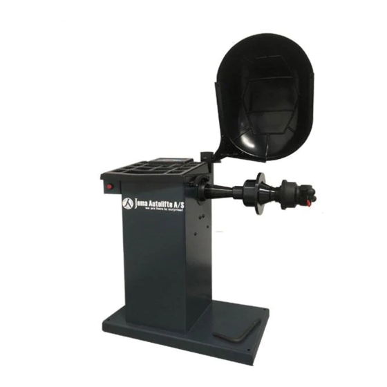
CHAPTER 1 DESCRIPTION OF THE MACHINE The wheel balancer DWC-8-E is intended to be used to balance dynamically passenger car and light truck wheels within one measuring run. 1. power switch 2. distance gauge 3. rubber pads 4. feeder 5. quick adapter 6. - Page 8 Description of keyboard (fig. 1 and 2) Verbal messages generated by the wheel balancer upon pressing a button are provided in square brackets. Button setting the width of a wheel to be balanced [WIDTH] Button setting diameter and distance of a wheel to be balanced [DIAMETER] or [DISTANCE] Button of selection of weights mounting manner with diode signalisation [RIM TYPE CHANGE]...
-
Page 9: Chapter 2 Technical Specifications
WARNING The wheel balancer was designed and manufactured to be used to dynamically balance passenger car and light truck wheels. It is prohibited to use it in any other way. The wheel balancer should not be used to wash wheels. CHAPTER 2 TECHNICAL SPECIFICATIONS Technical data - max. -
Page 10: Chapter 3 Safety
WARNING The wheel balancer DWC-8-E is intended to be used to balance passenger car and light truck wheels within one measuring run. It is prohibited to use it in any other way. In particular, the wheel balancer is not suitable for:... - Page 11 The manual contains the following captions concerning safety: Danger — indicates a possibility of danger which may lead to serious injuries Warning — indicates dangerous situations and/or types of manoeuvres which may lead to major or minor injuries Caution — indicates dangerous situations and/or types of manoeuvres which may lead to minor injuries and/or damage to the wheel balancer, wheel or any other objects Electric shock risk —...
- Page 12 Risk of damaging a component of the wheel balancer while it is in operation In order to manufacture a reliable and safe wheel balancer, Jema Autolifte used appropriate materials and manufacturing techniques adopted to the specified application of the machine.
-
Page 13: Chapter 4 Installation
CHAPTER 4 INSTALLATION WARNING The following operations may be performed only by persons who were previously trained to operate the machine to which this manual pertains. In order to prevent potential damage to the balancer or hazard of causing personal injuries, it is necessary to carefully follow the instructions below. - Page 14 Place of installation The wheel balancer DWC-8-E must be installed in a closed and dry place which will be heated in the autumn and winter period. The machine should be installed on a stable level floor. The wheel balancer should be installed on four rubber pads enclosed which should be placed under the flat legs welded to the machine base.
- Page 15 Components of the adapter set 1 – adapter; a – stud, b – flange 2 – screw for mounting the adapter on the shaft 3 – spring 4 – clamp nut 5 – centring cone No 2 1 43–82 mm 06.04.046 — W-St-6 6 –...
- Page 16 Clamp nut POSITION L (LOOSE) POSITION D (CLAMP) Fig. 5 Lever of the clamp nut revolves against the nut body within the limits indicated by a notch in the body (positions L and D). In the L position (LOOSE) the nut may be freely moved along the threaded stud of the adapter. In the D position (CLAMP) the nut may be screwed onto the threaded stud.
- Page 17 Mounting the wheel on the adapter Slide the wheel onto the adapter stud and position it with the edges of centre hole on the centring cone catch. Set the nut lug in the position LOOSE and screw the nut to the wheel until stop.
- Page 18 Adapter structure and equipment enabling to mount wheels with various rim shapes and centre hole diameters. - use of cone 5 or 6 with centring from the inner side of the rim: - nut of adapter “4” should be with a clamp “7” (see fig. 4 and 11) - the spring of the cone should be placed in such a way so that the smaller diameter of the springs supported against the cone base (fig.
- Page 19 Disassembly of the nut clamp Fig. 11 If in order to mount the wheel using centring discs and cones in the centring system from the outer side of the rim, it is required to remove the clamp from the nut. To remove the clamp, it should be pulled axially so that it is removed from the catch;...
-
Page 20: Chapter 5 Description Of Subprogrammes
CHAPTER 5 DESCRIPTION OF SUBPROGRAMMES 5.1 PROGRAMMING THE WHEEL BALANCER COMPUTER Operation of the wheel balancer computer The inspection shall be performed with the wheel mounted (tolerably only the rim) on the shaft. Connection of the wheel balancer computer Press power switch “1” on the wheel balancer Fig. 2 After completing the control testing, which is signalled with a sound, the measuring indicator screen shall display the icons as in Fig. - Page 21 rod of controller 1 Fig. 12 1 - controller 1a - controller rod 1b - controller arm 1c - controller head – rim 5.1.4 Selection of balancing programme Press ALU button on the keyboard. In the indicator screen the pictogram will be set at the height of pictogram Suitable programme is selected by pressing buttons option 1:...
- Page 22 option 3: balancing a wheel through clamping a weight on the inner side of a rim, and sticking another weight on the outer correction plane option 4: balancing a wheel through sticking a weight to the inner side of the correction plane, and clamping another weight on the outer side of a rim option 5: static balancing (with one weight for very thin rims);...
- Page 23 5.1.5 Entry of the cut-off threshold value Press the button on the keyboard. In the indicator screen the pictogram will be set at the height of pictogram . The wheel balancer has three values of the cut-off threshold: 2 grams, 5 grams and 40 grams. By pressing button it is possible to increase or decrease the cut-off threshold.
- Page 24 5.2 Wheel balancing Balancing of every wheel consists in determining the volume of imbalance expressed in grams for inner and outer correction plane and localising position of imbalance on the wheel. In order to clearly identify the volume of imbalance, it is necessary to enter the following data into the machine memory: WIDTH, DIAMETER, DISTANCE —...
- Page 25 After attaching weights of particular weight in particular positions perform a control measurement. In theory, the indicator should now display two zeros meaning that the remaining volume of imbalance does not exceed No 5 g, according to the set cut-off threshold. In practice, it does not have to be this way.
- Page 26 If the new position of imbalance is exactly at the opposite side of the previously attached weight, or it is slightly moved from this point, the weight should be decreased. 1 – weight 2 – new correction position If previously attached weight is below the new correction position, it should be moved upwards. 1 –...
- Page 27 It is difficult to clearly identify by what distance the weight should be moved in order to correct the residual imbalance. It depends on the value of imbalance to be corrected as well as the dimensions and position of the mounted weight. In general, it can be said that large weight and residual imbalance requires minor correction of the position.
- Page 28 CAUTION For balancing programmes 5 and 6, the correction weight for outer correction place should be attached in the plane of the faceplate (at the inner side of the rim). The stick-on weights cannot be removed and stuck again. Therefore, upon displaying the values of imbalance, a weight smaller by 5–10 g than the one indicated by the balancer should be stuck.
- Page 29 Spin the wheel to the left to the position defined in point 4.1 until the closest spoke reaches the vertical position. To accept the position press button . The computer shall save the wheel position as a position of sticking the first correction weight. The indicator screen shall display “Pt-2”, i.e.
- Page 30 3. Press button CAL i (the indicator screen will display symbol CAL!). Hold it until hearing a sound signal and displaying the following pictogram 4. Spin the shaft so as to reach the rotational speed of 125 rpm. Calibration cycle starts when the shaft revolutions are brought up to speed of 125 rpm.
- Page 31 Calibration cycle ends when the indicator displays numbers 0 and 79 or 0 and 80. CAUTION: Any other values signify incorrect calibration. In such a case contact the service centre. If there is no calibration device, the calibration should be performed with the use of a balanced wheel and weight of 80 g.
-
Page 32: Chapter 6 Notes On Operation
Jema Autolifte’s service centre shall result in loss of guarantee. Jema Autolifte reserves the right to make design changes or add improvements to its product, which may result in discrepancies with the information included in this operation manual. -
Page 33: Chapter 7 Maintenance
In order to maintain the wheel balancer in good technical condition, it is recommended to comply with the following instructions. FAILURE TO APPLY THESE RECOMMENDATIONS SHALL ABSOLVE JEMA AUTOLIFTE FROM ANY LIABILITY STIPULATED IN THE GUARANTEE. 1. Clean the wheel balancer at least once a month without using chemical cleaning agents and high pressure spray guns. -
Page 34: Chapter 8 Machine Scrapping
CHAPTER 8 MACHINE SCRAPPING ALL THE PRECAUTIONARY MEASURES DESCRIBED IN CHAPTER 3, APPLIED ALSO DURING ASSEMBLY, MUST BE APPLIED DURING SCRAPPING THE MACHINE. As in the case of assembly, disassembly must also be performed exclusively by properly trained personnel. Metal parts may be used as metal scrap. In any cases of scrapping, the machine neutralization of all the materials must be conducted in accordance with the regulations applicable in the country of the machine installation. -
Page 35: Chapter 9 Troubleshooting
CHAPTER 9 TROUBLESHOOTING CAUTION Any precautionary measures described in chapter 3 “SAFETY” and in chapter 7 “MAINTENANCE” must be applied during troubleshooting and repairs. SIGNS POSSIBLE CAUSE SUGGESTED PROCEDURE Damage to electric system — no power The wheel balancer does not Check the fuse generate control messages, Check if all electrical... - Page 36 Poland declare, under our exclusive responsability, that the product Wheel balancing machine Electromechanical and pneumatic device model DWC-8-E Serial number .........., concerned by this declaration, complies with all relevant requirements of the Machinery Directive: - Directive 2006/42/EC (safety machines), applicable in the essential requirements and relevant conformity assessment procedures, as well as on the essential...
- Page 37 Mr Wiesław Roguski is the person who responsible for the preparation the technical documentation of product and introducing changes in it. This EC Declaration of Conformity will be kept by Jema Autolifte of the product for 10 years from the date of produce the last unit and will available for market supervisory authorities for verification.
Need help?
Do you have a question about the DWC-8-E and is the answer not in the manual?
Questions and answers