Table of Contents
Advertisement
Quick Links
SD17040C
Stepper Driver
Table of Contents
General Information .................. 2
Introducing the SD17040C ....... 3
Specifications ............................ 4
Mounting the SD17040C ........... 5
Switch Settings ......................... 6
Connecting Your Controller ..... 7
Connecting Your Motor ............ 9
Indicator LED's .......................... 10
Verifying System Setup ............ 11
Troubleshooting ........................ 13
ADV ANC ED
MIC RO CON T RO L S INC.
Manual #: 940-0S110
Advertisement
Table of Contents

Subscribe to Our Youtube Channel
Related Manuals for AMCI SD17040C

Summary of Contents for AMCI SD17040C
-
Page 1: Table Of Contents
Manual #: 940-0S110 SD17040C Stepper Driver Table of Contents General Information ....2 Introducing the SD17040C ..3 Specifications ......4 Mounting the SD17040C ... 5 Switch Settings ......6 Connecting Your Controller ..7 Connecting Your Motor .... 9 Power Connector and Indicator LED’s ...... -
Page 2: General Information
[18] months. Within this warranty period, AMCI shall, at its option, repair or replace, free of charge, any equipment covered by this warranty which is returned, shipping charges prepaid, within eighteen months from date of invoice, and which upon examination proves to be defective in material or workmanship and not caused by accident, misuse, neglect, alteration, improper installation or improper testing. -
Page 3: Introducing The Sd17040C
Idle Current Reduction and the reasons why you wouldn’t. If these terms or ideas are new to you, we’re here to help. AMCI has a lot of information on our website and we are adding more all the time. If you can’t find what you’re looking for at http:///www.amci.com, send us an e-mail or call us. -
Page 4: Specifications
SPECIFICATIONS Driver Type Pulse Train Input Switch selectable to CW/CCW or Step/Direction. Two bipolar MOSFET H-bridges with 170Vdc output bus. 20KHz PWM current control. Motor Current Physical Dimensions Switch selectable from 1.0 to 4.0A in 0.1 Amp steps. Width: 2.1 inches max. Idle Current Reduction Depth: 4.0 inches max. -
Page 5: Mounting The Sd17040C
SD17040C enclosure and is a sufficient grounding point for most applications. When mounting the SD17040C on a surface that is electrically conductive and grounded, you should also take steps to ensure that the two are electrically bonded together. If necessary, remove paint for the bolt mounting surfaces of the panel to ensure adequate electrical bonding. -
Page 6: Switch Settings
SWITCH SETTINGS The SD17040C is configured by DIP switches on the top of the driver. The factory default setting has all switches in their off (0) position except for SB2-1. (CurrentLoop Gain = 1) All switch setting are latched. You must cycle power to the driver before changes take effect. -
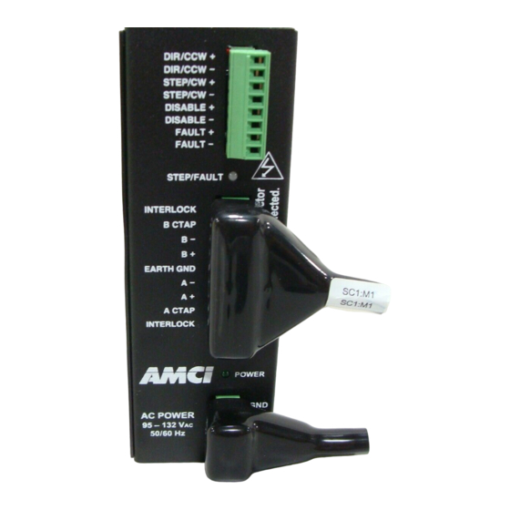
Page 7: Connecting Your Controller
CONNECTING YOUR CONTROLLER I/O Connector DIR/CCW The I/O connector on the SD17040C accepts inputs from your indexer DIR/CCW Indexer Inputs as well as the Disable Input and Fault Output. STEP/CW STEP/CW All inputs accept 5Vdc differential signals and can also be wired to... - Page 8 Both ends of the output are uncommitted, so it can be wired as a sourcing or sinking output. The figure shows a typical connection as a sourcing output. Open Collector Sourcing Output +5 to +24V FAULT+ PLC Input LIMIT FAULT– SD17040C Fault Output Shielded, Twisted Pair Cable FAULT OUTPUT Electrical Specifications 1Vdc @ 20 mA max: 30Vdc...
-
Page 9: Connecting Your Motor
CONNECTING YOUR MOTOR Compatible Motors The SD17040C will work with many different motors, including those not sold by AMCI. This section assumes that you have already chosen your motor and you are looking for wiring information. No wire colors are given because there is no single industry wide color coding standard for stepper motor wires. You must refer back to your motor data sheets for this information. -
Page 10: Power Connector And Indicator Led's
POWER CONNECTOR AND INDICATOR LED’s Power Connector The SD17040C operates on 115Vac. If 230Vac is the only power available, consider using one of the 230Vac drivers available from AMCI. Information on these drivers can be found on our website, http://www.amci.com. If this is not an option, a step-down transformer must be installed to power the SD17040C. -
Page 11: Verifying System Setup
Assuming a stable line voltage of 115 Vac, the following gains can be used for AMCI motors. These gain set- tings are factory suggestions and are average settings for our motors. Your system may benefit from increas- ing or decreasing these settings. - Page 12 8) If you are using the Fault Output, verify that it is On (conducting). Remove power from the SD17040C, disconnect the motor, and re-apply power. The STEP/FAULT LED should be red and the Fault Output should be off (not conducting).
-
Page 13: Troubleshooting
Symptom Solution My indexer/PLC reports a fault Your logic may be reversed. On the SD17040C, the Fault Output is on (con- ducts current) when the driver is working correctly and turns off (stops cur- from the SD17040C when every- rent flow) when there is a fault with the driver. Therefore, losing power to the thing seems fine. - Page 14 As noted above, sometimes a problem that appears to be with the motor is actually a problem with the indexer. The SD17040C has a Self-Test feature that allows you to verify motor opera- tion without an indexer. With power applied to the driver, toggle the SB4-1 switch. The motor will begin to rotate clockwise at 60 RPM.
- Page 16 ADV ANC ED MIC RO CONTROLS INC. ADV ANC ED MIC RO CONTROLS INC. ADV ANC ED MIC RO CONTROLS INC. ADV ANC ED MIC RO CONTROLS INC. 20 GEAR DRIVE, TERRYVILLE, CT 06786 T: (860) 585-1254 F: (860) 584-1973 www.amci.com LEADERS IN ADVANCED CONTROL PRODUCTS...
Need help?
Do you have a question about the SD17040C and is the answer not in the manual?
Questions and answers