Table of Contents
Advertisement
Advertisement
Table of Contents

Related Manuals for Emheater EM12 Series


Summary of Contents for Emheater EM12 Series
- Page 1 EMHEATER User Manual EM12 Series Frequency Inverter EMHEATER China EM Technology Limited Address : No.80, Baomin 2 road, Xixiang, Bao'an District,Shenzhen ,China Phone: 86-0755-29985851 Fax: 86-0755-29970305 Zip code: 518101 China EM Technology Limited Website : Http://www.emheater.com...
- Page 2 It adopts high-speed response, enhanced low-frequency loading capacity and supports torque control of SVC, which will bring you a new using experience. EM12 series frequency inverter is a continuable and vigorous product, and we will offer customized service to our customers! Before unpacking, please check carefully: ...
-
Page 3: Table Of Contents
1.2 General Precautions ..........................2 2. Product Information ............................. 5 2.1 Designation Rules ..........................5 2.2 Nameplate .............................. 5 2.3 EM12 Series Frequency Inverter ......................5 2.4 Technical Specifications ........................6 2.5 Product appearance and installation dimension ..................8 2.6 Options ..............................11 2.7 Daily maintenance of frequency inverters ................... - Page 4 EM12 User’s Manual Table of Contents 5.15 Group C0: Process Control PID Function ..................80 5.16 Group C1:Multi-function ........................85 5.17 Group C2: Simple PLC ........................86 5.17 Group C3: Swing Frequency, Fixed Length and Count ..............90 5.18 Group d0: Motor 1 Parameters ......................91 5.20 Group d1: Motor 1 vector control parameters ...................
-
Page 6: Safety Information And Precautions
Warning Read this manual carefully so that you have a thorough understanding. Installation, commissioning or maintenance may be performed in conjunction with this chapter. EMHEATER will assume no liability or responsibility for any injury or loss caused by improper operation. -
Page 7: General Precautions
1. Safety Information and Precautions EM12 User’s Manual Danger the frequency inverter. The input terminals (R, S, T) and output terminals (U, V, W) are properly connected. No short-circuit exists in the peripheral circuit. The wiring is fastened. Failure to comply will result in damage to frequency inverter. ... - Page 8 EM12 User’s Manual 1. Safety Information and Precautions long time, or in a regular check-up, in order to prevent the poor insulation of motor windings from damaging the frequency inverter. The motor must be disconnected from the frequency inverter during the insulation test. A 500-V mega-Ohm meter is recommended for the test.
- Page 9 1. Safety Information and Precautions EM12 User’s Manual Note: Do not connect the surge suppressor at the output side of the AC. 1.2.11 Altitude and de-rating In places where the altitude is above 1000 m and the cooling effect reduces due to thin air, it is necessary to de-rate the frequency inverter.
-
Page 10: Product Information
3 p has e 480 V Torq ue con tro l 3 ph ase 6 90V Diagram 2-1 Designation rules 2.2 Nameplate Diagram 2-2 Nameplate 2.3 EM12 Series Frequency Inverter Table 2-1 Models and technical data of EM12 Power Input Output Thermal Power... -
Page 11: Technical Specifications
2. Product Information EM12 User’s Manual Power Input Output Thermal Power Adaptable Motor Model Capacity Current Current Consumption (KVA) (KW) EM12-G2-018 18.5 0.716 EM12-G2-022 0.887 EM12-G2-030 1.11 EM12-G2-037 1.32 EM12-G2-045 1.66 EM12-G2-055 1.98 EM12-G2-075 2.02 Three-phase 380V,50/60Hz EM12-G3-d75/P3-1d5 5/5.8 2.1/3.8 0.75/1.5 0.050 EM12-G3-1d5/P3-2d2... - Page 12 EM12 User’s Manual 2. Product Information Item Specifications Speed stability accuracy ± 0.5% (SVC) ± 0.02% (FVC) Torque control accuracy ± 10% (SVC) ± 5% (FVC) G type: 60s for 150% of the rated current, 3s for 180% of the rated current Overload capacity P type: 60s for 120% of the rated current, 3s for 150% of the rated current Auto boost...
-
Page 13: Product Appearance And Installation Dimension
2. Product Information EM12 User’s Manual Item Specifications auxiliary frequency and frequency synthesis. Standard: 6 digital input (DI) terminals, one of which supports up to 50 kHz high-speed pulse input 3 analog input (AI) terminals, AI1,AI2 support 0V~10 V or 0mA~20mA Input terminal input, AI3 support -10V~+10V Expanding capacity:... - Page 14 EM12 User’s Manual 2. Product Information Diagram 2-4 Appearance and installation dimension of EM12 series (Plastic housing structure) Diagram 2-5 Appearance and installation dimension of EM12 series (Metal housing structure) Diagram 2-6 Appearance and installation dimension of EM12 series (Cabinet structure)
- Page 15 2. Product Information EM12 User’s Manual The housing types of the EM12 models are listed in the following table: 1PH 220 V 3PH 220 V 3PH 380 V Power 0.4kW~2.2kW 0.4kW~11kW 15kW~75kW 0.75kW~22kW 30kW~400kW Plastic Plastic Sheet metal Plastic Sheet metal Housing Type 2.5.2 Appearance and Installation Hole Dimension (mm) Appearance and installing dimension(mm)...
-
Page 16: Options
EM12 User’s Manual 2. Product Information Appearance and installing dimension(mm) Model Φd EM12-G3-355/P3-400 EM12-G3-400/P3-450 EM12-G3-450/P3-500 2.5.3 Appearance and installation dimension of external keypad (keypad tray) Diagram 2-7 Appearance and installation dimension of external keypad (keypad tray) 2.6 Options Please indicate if the following options are needed when placing order. Table 2-4 Options of EM12 frequency inverter Item Functions... -
Page 17: Warranty Items
2. Product Information EM12 User’s Manual inside of the frequency inverter, especially for the metal dust; 8. Clear up effectively the oil and dust on the cooling fan of frequency inverter. 2.7.2 Regular inspection Please regularly check frequency inverter, especially for the difficult checking place of running. Regular inspection items: 1. -
Page 18: Selection Guide Of Braking Component
EM12 User’s Manual 2. Product Information c) The damage caused by using the frequency inverter for abnormal functions; d) The relevant service fee is calculated according to the manufacturer’s standard, if there is contract, then it carries out subject to the contract. 2.9 Selection Guide of braking component Table 2-5 is the recommended value of braking resistor, users can select the different resistance value and power according to the actual situation,(but the resistance value must not be less than the recommended value in the table,... - Page 19 2. Product Information EM12 User’s Manual Recommend Recommend power Braking Model Remarks resistance value of of braking resistor unit braking resistor ≥ 65Ω EM12-G2-2d2 300W ≥ 45Ω EM12-G2-004 400W ≥ 22Ω EM12-G2-5d5 800W ≥ 16Ω EM12-G2-7d5 1000W ≥ 11Ω EM12-G2-011 1500W ≥...
- Page 20 EM12 User’s Manual 2. Product Information 2.9.3 Braking resistor connection description The braking resistor connection of EM12 series frequency inverter is showed as below: Brak ing Inverter Inverter Brakin g R esis tor B rak in g Res isto r...
-
Page 21: Installation Of Frequency Inverter
3. Installation of Frequency Inverter EM12 User’s Manual 3. Installation of Frequency Inverter 3.1 Installation environment 1. The place with indoor vents or ventilation devices. 2. The environment temperature shall be -10℃~40℃. If the temperature is over 40℃but less than 50℃, better to take down the cover of frequency inverter or open the front door of cabinet to facilitate heat dissipation. -
Page 22: Peripheral Devices Connection Diagram
EM12 User’s Manual 3. Installation of Frequency Inverter 3.3 Peripheral Devices Connection Diagram Diagram 3-2 Peripheral Devices Connection... -
Page 23: Instructions Of Main Circuit Peripheral Devices
3. Installation of Frequency Inverter EM12 User’s Manual 3.4 Instructions of Main Circuit Peripheral Devices Table 3-1 Main circuit peripheral devices use instructions Parts Name Installation Location Function Description The capacity of the circuit breaker shall be 1.5 to 2 times of the rated current of the inverter. -
Page 24: Model Selection Of Main Circuit Peripheral Devices
EM12 User’s Manual 3. Installation of Frequency Inverter 3.5 Model Selection of Main Circuit Peripheral Devices Table 3-2 Model Selection Diagram of Main Circuit Peripheral Devices (Recommended) Cable of Input Side Cable of Output Side Cable of Control Frequency inverter MCCB Contactor Main Circuit... -
Page 25: Removal And Mounting Of Operating Panel And Cover
3.6.1 Removal and mounting of operating panel (keypad) The operating panel of EM12 series Frequency inverter is a plug type, If you need to take it off when use or maintenance, please make sure the gentle actions, or it is easy to damage the plug type connection terminals on operating panel. -
Page 26: Connection Terminals Diagram Description
3. Installation of Frequency Inverter Diagram 3-5 The cover removal of plastic case 3.7 Connection Terminals Diagram Description Diagram 3-6 EM12 Series terminal distribution diagram 3.8 Sketch and Description of Main Circuit Terminals 3.8.1 Function and description of Main Circuit Terminals... -
Page 27: Cautions For Main Circuit Wiring
3. Installation of Frequency Inverter EM12 User’s Manual Three-phase 220V: EM12-G2-2d2~EM12-G2-045 Three-phase 380V: EM12-G3-004/P3-5d5~EM12-G3-090/P3-110 Three-phase 220V: EM12-G2-055~EM12-G2-075 Three-phase 380V: EM12-G3-110/P3-132~EM12-G3-400/P3-450 Terminal symbol Function description L、N Single-phase AC power input terminals R/L1, S/L2, T/L3 Three-phase AC power input terminals P+, PB Braking resistor connecting ○... - Page 28 EM12 User’s Manual 3. Installation of Frequency Inverter frequency setting. Length of cable between the inverter and motor Carrier frequency (d6-00) Less than 50m Less than 15kHz Less than 100 m Less than 10kHz More than 100m Less than 5kHz 3.9.3 Grounding Wiring ...
-
Page 29: Control Circuit And Main Circuit Terminals Description
3. Installation of Frequency Inverter EM12 User’s Manual shall be used. The shielding layer shall be connected to the grounding terminal PE of the inverter, and the signal cable shall be no longer than 50m. The wires of the control circuit terminals RA/RB/RC and other control circuit terminals shall be separately routed. - Page 30 EM12 User’s Manual 3. Installation of Frequency Inverter 3.10.2 Control Circuit Terminal Layout Diagram 3-11 EM12 Control Circuit Terminal Sketch Map 3.10.3 Description of control circuit terminals Table 3-4 Description of control circuit terminals Terminal Type Terminal Name Terminal function description Symbol Provide +10V power supply to external unit.
- Page 31 3. Installation of Frequency Inverter EM12 User’s Manual 3.10.4 Wiring of Analog Input Terminals When the voltage signal is used as analog input, it is vulnerable from outside interference. Please use shielding cable, and ensure that the shielding cable reliably connect to the grounding. The cable should be as short as possible, and keep away from power lines.
- Page 32 EM12 User’s Manual 3. Installation of Frequency Inverter Jumper Name Function Description Default Setting When the jumper is “COM”, COM connect with PE PE-COM When the jumper is “EMPTY”, COM disconnect with PE When the jumper is “GND”, GND connect with PE PE-GND When the jumper is “EMPTY”, GND disconnect with PE When the jumper is “V”, AI1 is with voltage input (0~10V).
-
Page 33: Operation And Display
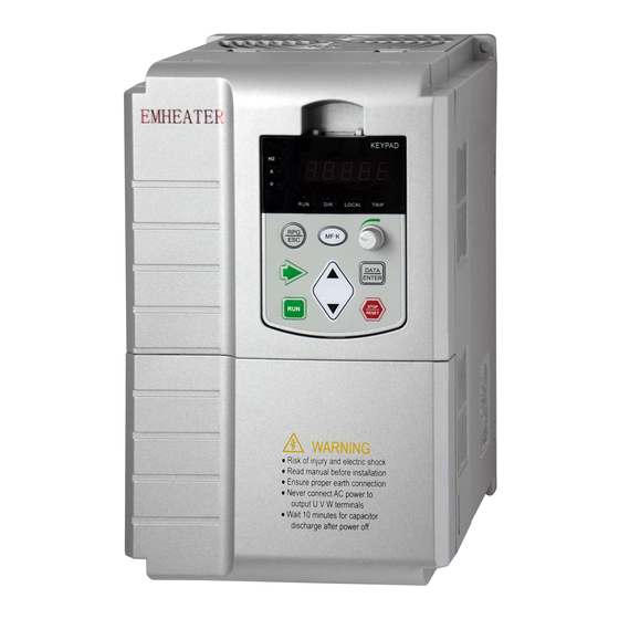
4. Operation and display EM12 User’s Manual 4. Operation and display 4.1 Instruction of operation and display Diagram 4-1 Operating panel 1. Description of indicator: RUN: OFF indicates that the frequency inverter is in the stop state and ON indicates that the frequency inverter is in the running state. -
Page 34: Viewing And Modifying Function Codes
EM12 User’s Manual 4. Operation and display Name Function Stop the frequency inverter when it is in the running state and perform the reset operation when it is in the fault state. The functions of this key are Stop/Reset STOP/RESET restricted by b9-00. -
Page 35: Password Setting
4. Operation and display EM12 User’s Manual When the frequency inverter is repowered on again after power failure, the parameters are recorded as before power failure and displaying. 4.4 Password Setting The frequency inverter provides the user password protection function. When A0-00 is set to a non-zero value, the value is the user password. -
Page 36: Description Of Function Codes
EM12 User’s Manual 5. Description of Function Codes 5. Description of Function Codes 5.1 Group b0: Basic Function Parameters Motor type selection Default AC asynchronous motor b0-00 Setting Range Permanent magnetic synchronous motor 0- select Motor 1 as AC asynchronous motor; 1-select Motor 1 as Permanent magnetic synchronous motor Motor control mode Default... - Page 37 5.Description of Function Codes EM12 User's Manual Main frequency source X selection Default Digital setting (Preset frequency b0-12, UP/DOWN modifiable, no-record after power off) Digital setting (Preset frequency b0-12, UP/DOWN modifiable, record after power off) b0-03 Setting Range Pulse setting Multi-function Built-in PLC Communication setting...
- Page 38 EM12 User’s Manual 5. Description of Function Codes The EM12 supports a maximum of 16 speeds implemented by 16 state combinations of four DI terminals (set with functions 12 to 15) in Group C1. The multiple segments speed indicates percentages of the value of b0-13 (Maximum frequency).
- Page 39 5.Description of Function Codes EM12 User's Manual Selection of auxiliary frequency Y range Default b0-05 Relative to maximum frequency Setting Range Relative to main frequency X Range of auxiliary frequency Y 100% Default b0-06 0%~150% Setting Range If X and Y operation is used, b0-05 and b0-06 are used to set the adjustment range of theauxiliary frequency source. You can set the auxiliary frequency to be relative to either maximum frequency or main frequency X.
- Page 40 EM12 User’s Manual 5. Description of Function Codes Binding command source to frequency source Default Unit's digit: Binding keypad command to following frequency source. No binding Frequency source by digital setting Pulse setting (HDI) b0-09 Setting Multi-function Range Simple PLC Communication setting Ten's digit: Binding terminal command to frequency source ;0~9, same as unit's digit Hundred's digit: Binding communication command to frequency source;...
- Page 41 5.Description of Function Codes EM12 User's Manual value of this parameter. The output frequency of the EM12 can reach up to 3000 Hz. To take both frequency reference resolution and frequency input range into consideration, you can set the number of decimal places for frequency reference in b0-11. ...
- Page 42 EM12 User’s Manual 5. Description of Function Codes running frequency and setting frequency are different, therewill be a large difference between the frequency inverter's performance during the acceleration/ deceleration process. Acceleration/Deceleration mode Default Linear acceleration/ deceleration b0-20 Setting S-curve acceleration/deceleration A Range S-curve acceleration/deceleration B It is used to set the frequency changing mode during the frequency inverter start and stop process.
- Page 43 5.Description of Function Codes EM12 User's Manual Diagram 5-3 Acceleration/Deceleration time The EM12 provides totally four groups of acceleration/deceleration time for selection. You can perform switchover by using a DI terminal. And you can set the four groups of acceleration/deceleration time through the following function codes: Group 1: b0-21, b0-22;...
-
Page 44: Group B1: Start/Stop Control Parameters
EM12 User’s Manual 5. Description of Function Codes Note: Modifying this parameter will make the decimal places of all frequency-related parameters change and corresponding frequency values change. Pay attention for this in on-site application. Acceleration/Deceleration time base frequency Default Maximum frequency (b0-13) b0-26 Setting Set frequency... - Page 45 5.Description of Function Codes EM12 User's Manual Startup frequency Default 0.00 Hz b1-03 Setting Range 0.00~10.00 Hz Startup frequency holding time Default 0.0s b1-04 Setting Range 0.0s~100.0s To ensure the motor torque at frequency inverter startup, set a proper startup frequency. In addition, to build excitation when the motor starts up, the startup frequency must be held for a certain period.
-
Page 46: Group B2: Auxiliary Functions
EM12 User’s Manual 5. Description of Function Codes Setting Range 0.00 Hz ~ maximum frequency DC braking waiting time of stopping Default 0.0s b1-09 Setting Range 0.0s~100.0s DC braking current of stopping Default b1-10 0%~100% Setting Range DC braking time of stopping 0.0s Default b1-11... - Page 47 5.Description of Function Codes EM12 User's Manual Acceleration time 2 Default Model dependent b2-03 Setting Range 0.0s~6500.0s Deceleration time 2 Default Model dependent b2-04 Setting Range 0.0s~6500.0s Acceleration time 3 Default Model dependent b2-05 0.0s~6500.0s Setting Range Deceleration time 3 Model dependent Default b2-06...
- Page 48 EM12 User’s Manual 5. Description of Function Codes Diagram 5-7 Diagrams when the jump frequencies are valid during acceleration/deceleration Frequency switchover point between acceleration time 1 and Default 0.00Hz acceleration time 2 b2-13 Setting Range 0.00 Hz ~maximum frequency Frequency switchover point between deceleration time 1 and 0.00Hz Default deceleration time 2...
- Page 49 5.Description of Function Codes EM12 User's Manual Forward/Reverse rotation dead-zone time Default 0.0s b2-16 Setting Range 0.0~3000.0s It is used to set the time when the output is 0 Hz at transition of the frequency inverter forward rotation and reverse rotation, as shown in the following figure.
- Page 50 EM12 User’s Manual 5. Description of Function Codes Setting running time reach threshold Default b2-21 Setting Range 0~65000 h It is used to set the accumulative running time threshold of the Frequency inverter. If the accumulative running time (b9-09) reaches the value set in this parameter, the corresponding DO terminal becomes ON. Action after running time reached Default Continue to run...
-
Page 51: Group B3: Input Terminals
5.Description of Function Codes EM12 User's Manual These parameters are used to implement the frequency inverter timing function. If b2-28 is set to 1, the frequency inverter starts to time at startup. When the set timing durationreached, the frequency inverter stops automatically, and meanwhile the corresponding DO outputs ON signal. The frequency inverter starts timing from 0.0min each time it starts up and the remaining timing duration can be checked by U0-20. - Page 52 EM12 User’s Manual 5. Description of Function Codes Value Function Description Multi-function terminal 3 Multi-function terminal 4 Terminal UP If the frequency is determined by external terminals, the terminals with the two functions are used as increment and decrement commands for frequency modification. Terminal DOWN When the frequency source is digital setting, they are used to adjust the frequency.
- Page 53 5.Description of Function Codes EM12 User's Manual Value Function Description frequency function pauses. Counter input This terminal is used to count pulses. Counter reset This terminal is used to clear the counter status. Length count input This terminal is used to count the length. Length reset This terminal is used to clear the length.
- Page 54 EM12 User’s Manual 5. Description of Function Codes Reference Setting Corresponding Parameter Reference 0 C1-00 Reference 1 C1-01 Reference 2 C1-02 Reference 3 C1-03 Reference 4 C1-04 Reference 5 C1-05 Reference 6 C1-06 Reference 7 C1-07 Reference 8 C1-08 Reference 9 C1-09 Reference 10 C1-10...
- Page 55 5.Description of Function Codes EM12 User's Manual Code Name Value Function Description b3-13 Terminal command mode Two-line 1 b3-00 DI1 function selection Forward RUN (FWD) b3-01 DI2 function selection Reverse RUN (REV) Diagram 5-10 Setting of two-line mode 1 As shown in the preceding figure, when only K1 is ON, the frequency inverter instructs forward rotation. When only K2 is ON, the frequency inverter instructs reverse rotation.
- Page 56 EM12 User’s Manual 5. Description of Function Codes Diagram 5-12 Setting of three-line mode 1 As shown in the preceding figure, if SB1 is ON, the frequency inverter instructs forward rotation when Sb2 is pressed to be ON, and instructs reverse rotation when SB3 is pressed to be ON. The frequency inverter stops immediately after SB1 becomes OFF.
-
Page 57: Group B4: Output Terminals
5.Description of Function Codes EM12 User's Manual DI1 ON delay time Default 0.0s b3-15 Setting Range 0.0s~3000.0s DI1 OFF delay time Default 0.0s b3-16 Setting Range 0.0s~3000.0s DI2 ON delay time 0.0s Default b3-17 0.0s~3000.0s Setting Range DI2 OFF delay time Default 0.0s b3-18... - Page 58 EM12 User’s Manual 5. Description of Function Codes terminal (used for high-speed pulse output or open-collector switch signal output) as standard. If these output terminals cannot satisfy requirements, use an optional I/O extension card. FM terminal output mode Default Pulse output (FMP) b4-00 Setting Range...
- Page 59 5.Description of Function Codes EM12 User's Manual Value Function Description The terminal becomes ON when the count value reaches the value set in Set count value reached C3-08. Designated count value The terminal becomes ON when the count value reaches the value set in reached C3-09.
- Page 60 EM12 User’s Manual 5. Description of Function Codes Value Function Description Accumulative power- on If the frequency inverter accumulative power-on time (b9-08) exceeds the time reached value set in b2-20, the terminal becomes ON. Accumulative running time If the accumulative running time of the frequency inverter exceeds the time reached set in b2-21, the terminal becomes ON.
- Page 61 5.Description of Function Codes EM12 User's Manual Diagram 5-14 FDT level Detection width of frequency Default 50.00 Hz b4-24 0.00 Hz~ maximum frequency Setting Range Frequency detection value 2 (FDT2) Default 5.0% b4-25 Setting Range 0.0%~100.0% (FDT1 level) The frequency detection function is the same as FDT1 function. For details, refer to the descriptions of b4-22 and b4-23.
- Page 62 EM12 User’s Manual 5. Description of Function Codes Any frequency reaching detection value 2 Default 50.00 Hz b4-29 Setting Range 0.00 Hz ~ maximum frequency Any frequency reaching detection amplitude 2 0.0% Default b4-30 Setting Range 0.0%~100.0% (maximum frequency) If the output frequency of the frequency inverter is within the positive and negative amplitudes of the any frequency reaching detection value, the corresponding DO becomes ON.
- Page 63 5.Description of Function Codes EM12 User's Manual Over current output threshold Default 200.0% b4-33 Setting Range 0.0%~300.0% (rated motor current) Over current output detection delay time 0.00s Default b4-34 Setting Range 0.00s~600.00s If the output current of the frequency inverter is equal to or higher than the over current threshold and the duration exceeds the detection delay time, the corresponding DO becomes ON.
-
Page 64: Group B5: Pulse/Analog Input Terminals
EM12 User’s Manual 5. Description of Function Codes IGBT module temperature threshold Default 75°C b4-39 Setting Range 25~100°C When the heatsink temperature of the frequency inverter reaches the value of this parameter, the corresponding DO becomes ON, indicating that the IGBT module temperature reaches the threshold. 5.6 Group b5: Pulse/Analog input terminals Pulse minimum input(HDI) 0.00 kHz... - Page 65 5.Description of Function Codes EM12 User's Manual Setting Range -100.0% ~100.0% AI1 input filter time 0.01s Default b5-11 0.00s~10.00s Setting Range AI2 input minimum value 0.00V Default b5-12 Setting Range 0.00 V~10.00 V Corresponding setting of AI2 minimum input 0.0% Default b5-13 Setting Range...
- Page 66 EM12 User’s Manual 5. Description of Function Codes b5-17 (AI1 filter time) is used to set the software filter time of AI1. If the analog input is liable to interference, increase the value of this parameter to stabilize the detected analog input. However, increase of the AI filter time will slow down the response of analog detection.
-
Page 67: Group B6: Pulse/Analog Output Terminals
5.Description of Function Codes EM12 User's Manual 0.5% AI3 jump amplitude Default b5-43 Setting Range 0%~100.0% AI curve selection H321 Default Unit’s digit:AI1 curve selection curve 1(2 point, refer b5-07~b5-10) curve 2(2 point, refer b5-12~b5-15) b5-44 curve 3(2 point, refer b5-17~b5-20) Setting Range curve 4(4 point, refer b5-22~b5-29)... -
Page 68: Group B7: Virtual Digital Input (Vdi)/Digital Output (Vdo) Terminals
EM12 User’s Manual 5. Description of Function Codes Value Function Range (Corresponding to Pulse or Analog Output Range 0.0%~100.0%) 0V~10 V 0V~10 V Length 0~ maximum set length Count value 0 ~ maximum count value Communication setting 0~32767 Maximum FMP output frequency Default 50.00 kHz b6-03... - Page 69 5.Description of Function Codes EM12 User's Manual VDI state setting Default 00000 Unit's digit: VDI1. Invalid Valid b7-06 Setting Ten's digit: VDI2 0, 1 (same as VDI1) Range Hundred's digit: VDI3. 0, 1 (same as VDI1) Thousand's digit: VDI4. 0, 1 (same as VDI1) Ten thousand's digit: VDI5.
- Page 70 EM12 User’s Manual 5. Description of Function Codes The functions of these parameters are to use AI as DI. When AI is used as DI, the AI state is high level if the AI input voltage is 7 V or higher and is low level if the AI input voltage is 3 V or lower. If the AI input voltage is between 3 V and 7 V,the AI state is hysteresis.
-
Page 71: Group B8: Ai/Ao Correction
5.Description of Function Codes EM12 User's Manual Thousand's digit: VDO4. 0, 1 (same as unit's digit) Ten thousand's digit: VDO5. 0, 1 (same as unit's digit) VDO functions are similar to the DO functions on the control board. The VDO can be used together with VDIx to implement some simple logic control. -
Page 72: Group B9: Keypad And Display
EM12 User’s Manual 5. Description of Function Codes 5.10 Group b9: Keypad and Display STOP/RESET key function Default STOP/RESET key enabled only in operation panel control b9-00 Setting Range STOP/RESET key enabled in any operation mode STOP/RESET key function Default MF.K key disabled Setting Range... - Page 73 5.Description of Function Codes EM12 User's Manual If a parameter needs to be displayed during the running, set the corresponding bit to 1, and set b9-02 to the hexadecimal equivalent of this binary number. LED display running parameters 2 H.0000 Default 0000~FFFF: b9-03...
- Page 74 EM12 User’s Manual 5. Description of Function Codes If a parameter needs to be displayed during the running, set the corresponding bit to 1, and set b9-04 to the hexadecimal equivalent of this binary number. Load speed display coefficient 1.0000 Default b9-05 Setting Range...
-
Page 75: Group Ba: Communication Parameters
5.Description of Function Codes EM12 User's Manual (display of 2 decimal places). Heatsink temperature Default b9-07 Setting Range 0.0°C ~100.0°C It is used to display the temperature of heatsink. Different inverter model has different temperature value for over-temperature protection. Accumulative power-on time Default b9-08 0~65535 h... -
Page 76: Group Bb: Fault And Protection
EM12 User’s Manual 5. Description of Function Codes Broadcast address Default bA-03 1~249 (0: Broadcast address) Valid for Modbus Setting Range When the local address is set to 0, that is, broadcast address, it can realize the broadcast function of host computer. The address is unique;... - Page 77 5.Description of Function Codes EM12 User's Manual This parameter is used to display the delivered model and cannot be modified. 0: Applicable to variable torque load (fan and pump) with rated parameters specified. 1: Applicable to constant torque general load with rated parameters specified. Motor overload protection selection Default bb-01...
- Page 78 EM12 User’s Manual 5. Description of Function Codes may occur. If the overvoltage stall gain is set to 0, the overvoltage stall function is disabled. The overvoltage stall protective voltage setting 100% corresponds to the base values in the following table: Voltage Class Corresponding Base Value Single-phase 220 V...
- Page 79 5.Description of Function Codes EM12 User's Manual Protection of short-circuit to ground after power-on Default Disabled bb-08 Setting Range Enabled It is used to determine whether to check the motor is short-circuited to ground after power-on of the frequency inverter. If this function is enabled, the frequency inverter's UVW will have voltage output a while after power-on. Fault auto reset times Default bb-09...
- Page 80 EM12 User’s Manual 5. Description of Function Codes Range Enabled Off load detection level 10.0% Default bb-15 0.0%~100.0% (rated motor current) Setting Range Off load detection time Default 1.0s bb-16 Setting Range 0.0s~60.0s Ifoff load protection is enabled, when the output current of the frequency inverter is lower than the detection level (bb-15) and the duration time exceeds the detection time (bb-16), the output frequency of frequency inverter automatically declines to 7% of the rated frequency.
- Page 81 5.Description of Function Codes EM12 User's Manual to normal. If bb-21 = 2, when instantaneous power failure or sudden voltage dip, the frequency inverter decelerates to stop. Diagram 5-24 Frequency inverter action diagram of instantaneous power failure Type of motor temperature sensor Default No temperature sensor bb-25...
- Page 82 EM12 User’s Manual 5. Description of Function Codes Overvoltage threshold Default 810V bb-28 200.0~2500.0 V Setting Range It is used to set the overvoltage threshold of the frequency inverter. The default values of different voltage classes are listed in the following table. Voltage Class Default Overvoltage Threshold Single-phase 220 V...
- Page 83 5.Description of Function Codes EM12 User's Manual Fault protection action selection 1 Default 00000 Unit's digit: Motor overload, Err11. Free stop Stop according to the stop mode bb-32 Continue to run Setting Range Ten's digit: Power input phase loss, Err12. Same as unit's digit Hundred's digit: Power output phase loss, Err13.
-
Page 84: Group Bc: Fault Detection Parameters
EM12 User’s Manual 5. Description of Function Codes The setting of bb-38 is a percentage relative to the maximum frequency. 5.13 Group bC: Fault detection Parameters bC-00 First fault type bC-01 0~99 Second fault type bC-02 Third fault type (latest) It is used to record the types of the most recent three faults of the frequency inverter. -
Page 85: Group Bd Motor Protection
5.Description of Function Codes EM12 User's Manual Power-on time of 1st fault bC-25 Default Running time of 1st fault bC-26 Default Description bC-11~bC-26 same as bC-03~bC-10. 5.14 Group bd Motor protection Overset alarm current value 0.00 Default bd-00 Setting Range 0.0~600A Overcurrent alarm delay time Default... - Page 86 EM12 User’s Manual 5. Description of Function Codes The PID setting change time indicates the time required for PID setting changing from 0.0% to 100.0%. The PID setting changes linearly according to the change time, reducing the impact caused by sudden setting change on the system.
- Page 87 5.Description of Function Codes EM12 User's Manual C0-06 (Proportional gain Kp1) It decides the regulating intensity of the PID regulator. The higher the Kp1 is, the larger the regulating intensity is. The value 10.00 indicates when the deviation between PID feedback and PID setting is 100.0%, the adjustment amplitude of the PID regulator on the output frequency reference is the maximum frequency.
- Page 88 EM12 User’s Manual 5. Description of Function Codes Diagram 5-26 PID parameters switchover PID integral property Default Unit's digit: Integral separated. Invalid Valid C0-15 Setting Range Ten's digit: Whether to stop integral operation when the output reaches the limit. Continue integral operation Stop integral operation ...
- Page 89 5.Description of Function Codes EM12 User's Manual Frequency upper limit of PID reverse rotation Default 2.00 Hz C0-18 0.00 ~ maximum frequency Setting Range In some situations, only when the PID output frequency is a negative value (frequency inverter reverse rotation), PID setting and PID feedback can be equal.
-
Page 90: Group C1:Multi-Function
EM12 User’s Manual 5. Description of Function Codes Default PID operation at stop C0-27 No PID operation at stop Setting Range PID operation at stop It is used to select whether to continue PID operation in the state of stopping. Generally, to set the PID operation stops when the frequency inverter stops. -
Page 91: Group C2: Simple Plc
5.Description of Function Codes EM12 User's Manual Multi-function 14 Default 0.0% C1-14 -100.0%~100.0% Setting Range Multi-function 15 Default 0.0% C1-15 -100.0%~100.0% Setting Range Multi-function can be the setting source of frequency, V/F separated voltage and processPID. The Multi-function is relative value and ranges from -100.0% to 100.0%. As frequency source, it is a percentage relative to the maximum frequency. - Page 92 EM12 User’s Manual 5. Description of Function Codes Diagram 5-28 Simple PLC when used as frequency source Simple PLC record selection Default Unit's digit: Record of power failure. no record after power off C2-01 record after power off Setting Range Ten's digit: Record of stopping no record after stopping record after stopping...
- Page 93 5.Description of Function Codes EM12 User's Manual Acceleration/deceleration time of simple PLC Segment 3 Default C2-09 Setting Range Running time of simple PLC Segment 4 Default 0.0s (h) C2-10 Setting Range 0.0s(h)~6553.5s(h) Acceleration/deceleration time of simple PLC Segment 4 Default C2-11 Setting Range Running time of simple PLC Segment 5...
- Page 94 EM12 User’s Manual 5. Description of Function Codes Setting Range 0.0s(h)~6553.5s(h) Acceleration/deceleration time of simple PLC Segment 14 Default C2-31 Setting Range Running time of simple PLC Segment 15 0.0s (h) Default C2-32 Setting Range 0.0s(h)~6553.5s(h) Acceleration/deceleration time of simple PLC Segment 15 Default C2-33 Setting Range...
-
Page 95: Group C3: Swing Frequency, Fixed Length And Count
5.Description of Function Codes EM12 User's Manual Acceleration time of Segment 7 Default 10.0s C2-50 0.0S-3000.0S Setting Range Deceleration time of Segment 7 Default 10.0s C2-51 0.0S-3000.0S Setting Range Acceleration time of Segment 8 Default 10.0s C2-52 0.0S-3000.0S Setting Range Deceleration time of Segment 8 Default 10.0s... -
Page 96: Group D0: Motor 1 Parameters
EM12 User’s Manual 5. Description of Function Codes Default 1.000Mpa Full scale maximum pressure (Mpa) C3-01 Setting Range 0.000~60.000Mpa Default 0.001Mpa Pressure lower limit (Mpa) C3-02 0.000~60.000Mpa Setting Range 1.000Mpa Default Pressure upper limit (Mpa) C3-03 0.000~60.000Mpa Setting Range 0.001Mpa Default Sleep wakeup pressure (Mpa) C3-04... - Page 97 5.Description of Function Codes EM12 User's Manual Mutual inductive reactance (asynchronous motor) Default Model dependent 0.1mH~6553.5 mH (Frequency inverter power≤ 55 kW) d0-08 Setting Range 0.01mH~655.35 mH (Frequency inverter power ≥75 kW) No-load current (asynchronous motor) Default Model dependent 0.01A ~ d0-02 (Frequency inverter power ≤55 kW) d0-09 Setting Range 0.1A to d0-02 (Frequency inverter power ≥75 kW)
- Page 98 EM12 User’s Manual 5. Description of Function Codes motor. Only ABZ incremental encoder and resolver are applicable to asynchronous motor. After installation of the PG card is complete, set this parameter properly based on the actual condition. Otherwise, the frequency inverter cannot run properly. Encoder type selection Default Forward...
-
Page 99: Group D1: Motor 1 Vector Control Parameters
5.Description of Function Codes EM12 User's Manual It is applicable to scenarios where complete auto-tuning cannot be performed because the asynchronous motor cannot be disconnected from the load. Before performing static auto-tuning, properly set the motor type and motor nameplate parameters of d0-00 ~ d0-04 firstly. - Page 100 EM12 User’s Manual 5. Description of Function Codes Speed/Torque control selection Default d1-00 Speed control Setting Range Torque control It is used to select the frequency inverter's control mode: speed control or torque control. The EM12 provides DI terminals with two torque related functions, function 21 (Torque control prohibited) and function 20 (Speed control/Torque control switchover).
- Page 101 5.Description of Function Codes EM12 User's Manual The speed dynamic response characteristics in vector control can be adjusted by setting the proportional gain and integral time of the speed regulator. To achieve a faster system response, increase the proportional gain and reduce the integral time. Be aware that this may lead to system oscillation.
- Page 102 EM12 User’s Manual 5. Description of Function Codes Speed loop integral property Default d1-18 Integral separation disabled Setting Range Integral separation enabled For SVC, it is used to adjust speed stability accuracy of the motor. When the motor with load runs at a very low speed, increase the value of this parameter;...
- Page 103 5.Description of Function Codes EM12 User's Manual range is -200.0% ~ 200.0%, indicating the frequency inverter's maximum torque is twice of the frequency inverter's rated torque. If the torque setting is positive, the frequency inverter rotates in forward direction. If the torque setting is negative, the frequency inverter rotates in reverse direction.
-
Page 104: Group D2: Motor 1 V/F Control Parameters
EM12 User’s Manual 5. Description of Function Codes acceleration/deceleration time of the slave in torque control is set to 0.0s. 5.20 Group d2: Motor 1 V/F Control Parameters Group d2 is valid only for V/F control. The V/F control mode is applicable to low requirement load applications (fan or pump) or applications where one frequency inverter operates multiple motors or there is a large difference between the frequency inverter power and the motor power. - Page 105 5.Description of Function Codes EM12 User's Manual frequency inverter at low frequency by modifying d2-01. If the torque boost is set to too large, the motor is easily overheated, and the frequency inverter easily suffers over current. If the load is large and the motor startup torque is insufficient, increase the value of d2-01. If the load is small, decrease the value of d2-01.
- Page 106 EM12 User’s Manual 5. Description of Function Codes At low frequency, higher voltage may cause motor overheat or even burnt and cause frequency inverter over current stall or over current protection. Diagram 5-32 Setting of multi-point V/F curve V/F slip compensation coefficient Default 0.0% d2-09...
- Page 107 5.Description of Function Codes EM12 User's Manual V/F curve setting Default Digital setting (d2-13) Pulse setting (HDI) d2-12 Setting Range Multi-function Simple PLC Communication setting Note: 100.0% corresponds to the rated motor voltage Voltage digital setting for V/F separation Default d2-13 0 V ~ rated motor voltage Setting Range...
-
Page 108: Group D3 To D5: Relevant Parameters Of Motor 2
5.22 Group d3 to d5: Relevant parameters of motor 2 EM12 series support the switchover of two groups of motor parameters, and the two motors can separately set the motor nameplate parameters, motor auto-tuning parameters, V/F control or vector control mode, the related parameters of encoder and the related performance parameters of V/F control or vector control mode. - Page 109 5.Description of Function Codes EM12 User's Manual frequency, note that if the set carrier frequency is higher than factory setting, it will lead to an increase in temperature rise of the frequency inverter's heatsink. In this case, you need to de-rate the frequency inverter. Otherwise, the frequency inverter may overheat and alarm.
-
Page 110: Group U0: Monitoring Parameters
EM12 User’s Manual 5. Description of Function Codes For high power frequency inverter, compensation mode 2 is recommended. Random PWM depth Default d6-05 0: Random PWM invalid Setting Range 1~10: Random PWM carrier frequency depth The setting of random PWM depth can make the motor shrill noise to soft and reduce the electromagnetic interference to other equipments. - Page 111 5.Description of Function Codes EM12 User's Manual It displays the frequency inverter's output current in the running state. Output power Default U0-05 Display Range 0~32767 It displays the frequency inverter's output power in the running state. Output torque Default U0-06 -200.0%~200.0% Display Range It displays the frequency inverter's output torque in the running state.
- Page 112 EM12 User’s Manual 5. Description of Function Codes Input pulse frequency Default U0-18 Display Range 0.00kHz ~100.00 kHz It displays the high-speed pulse sampled frequency of HDI, in minimum unit of 0.01 kHz. Feedback speed, unit:0.01Hz Default U0-19 -3000.0Hz~3000.0 Hz Display Range -300.00Hz~300.00 Hz It displays the actual output frequency of the frequency inverter.
- Page 113 5.Description of Function Codes EM12 User's Manual It displays the motor running frequency measured by the encoder. If b0-11 (frequency command resolution) is 1, the display range is -3200.0Hz ~ 3200.0Hz If b0-11 (frequency command resolution) is 2, the display range is -320.00Hz ~ 320.00Hz. Main frequency X Default U0-30...
- Page 114 EM12 User’s Manual 5. Description of Function Codes The value increase when the encoder rotates in forward direction and decreases when the encoder rotates in reverse direction. After increasing to 65535, the value starts to increase from 0 again. After decreasing to 0, the value starts to decrease from 65535 again.
-
Page 115: Group A0: System Parameters
5.Description of Function Codes EM12 User's Manual DI function state visual display 2 Default U0-44 Display Range It displays whether the DI functions 41~59 are valid. The display format is similar to U0-42. The 7-segment LEDs display functions 41–48, 49–56 and 57–59, respectively from right to left. Phase Z signal counting Default U0-46... - Page 116 EM12 User’s Manual 5. Description of Function Codes disabled. Product number Model dependent Default A0-01 Display Range Frequency inverter product number Default Model dependent Software version A0-02 Software version of control board Display Range Parameter modification property Default A0-07 Modifiable Setting Range Not modifiable...
-
Page 117: Emc (Electromagnetic Compatibility)
6. EMC (Electromagnetic compatibility) EM12 User’s Manual 6. EMC (Electromagnetic compatibility) 6.1 Definition Electromagnetic compatibility is the ability of the electric equipment to run in the electromagnetic interference environment and implement its function stably without interferences on the electromagnetic environment. 6.2 EMC Standard Description In accordance with the requirements of the national standard GB/T12668.3, the inverter needs to comply with electromagnetic interference and anti-electromagnetic interference requirements. - Page 118 EM12 User's Manual 6. EMC(Electromagnetic compatibility) 6.3.3 Handling method for the interferences of the surrounding equipment on the inverter The electromagnetic interference on the inverter is generated because plenty of relays, contactors and electromagnetic brakes are installed near the inverter. When the inverter has error action due to the interferences, the following measures can be taken: 1) Install surge suppressor on the devices generating interference;...
- Page 119 6. EMC (Electromagnetic compatibility) EM12 User’s Manual generate error action. The solution is to reduce the carrier frequency or install output reactor. It is recommended that thermal relay not be installed before the motor when using the inverter, and that electronic over current protection function of the inverter be used instead.
-
Page 120: Fault Diagnosis And Solution
EM12 User’s Manual 7. Fault Diagnosis and Solution 7. Fault Diagnosis and Solution 7.1 Fault Alarm and Countermeasures EM12 inverter has 35 types of warning information and protection function. In case of abnormal fault, the protection function will be invoked, the inverter will stop output, and the faulty relay contact of the inverter will start, and the fault code will be displayed on the display panel of the inverter. - Page 121 7. Fault Diagnosis and Solution EM12 User’s Manual Fault Type Display Possible Causes Solutions 1: The output circuit is grounded or short 1: Eliminate external faults. circuited. 2: Motor auto-tuning is not performed. 2: Perform the motor auto-tuning. Over current 3: The voltage is too low.
- Page 122 EM12 User’s Manual 7. Fault Diagnosis and Solution Fault Type Display Possible Causes Solutions 1: The cable connecting the frequency 1: Eliminate external faults. inverter and the motor is faulty. 2: The frequency inverter's three-phase 2: Check whether the motor three phase Power output Err13 outputs are unbalanced when the motor is...
-
Page 123: Common Faults And Solutions
7. Fault Diagnosis and Solution EM12 User’s Manual Fault Type Display Possible Causes Solutions 1: The signal of user-defined fault 1 is 1: Reset the operation. User-defined input via DI. Err27 fault 1 2:The signal of user-defined fault 1 is 2: Reset the operation. - Page 124 EM12 User’s Manual 7. Fault Diagnosis and Solution Fault Possible Causes Solutions 1: There is no power supply to the frequency 1: Check the power supply. inverter or the power input to the frequency inverter is too low. 2: The power supply of the switch on the 2: Check the DC bus voltage.
- Page 125 7. Fault Diagnosis and Solution EM12 User’s Manual Fault Possible Causes Solutions 3: The PG card is faulty. 3: Ask for technical support. 4: The drive board is faulty. 1: The motor parameters are set improperly. 1: Re-set motor parameters or The frequency re-perform the motor auto- inverter reports...
-
Page 126: Appendix I.modbus Communication Protocol
3.5byte, it indicates that a new start of communication frame. EM12 series inverter has built-in the Modbus-RTU communication protocol, and is applicable to response the slave “Inquiry/command” or doing the action according to the master’s “Inquiry / Command” and response to the... - Page 127 Communication data structure Modbus protocol communication data format of EM12 series inverter is shown as following. The inverter only support the reading and writing of Word type parameters, the corresponding reading operation command is “0x03”, the writing operation command is “0x06”.
- Page 128 EM12 User’s Manual Appendix I 1Byte 2Byte >3.5Byte 1Byte 1Byte Slave reads and Target Read the Free response error correction and station command Error type Free (Start frame) frame address (0x83) L……H Calculate CRC Error types: correction 01-Command code error 02-Address error 1Byte 2Byte...
- Page 129 Appendix I EM12 User’s Manual is exclusive ORed with the register contents. Then the result is shifted in the direction of the least significant bit (LSB), with a zero filled into the most significant bit (MSB) position. The LSB is extracted and examined. If the LSB was a 1, the register is then exclusive ORed with a preset, fixed value.
- Page 130 EM12 User’s Manual Appendix I Inquiry address When Function code group Communication inquiry address Communication modifies RAM A0~ A2 0xA000~ 0xA2FF 0x4000~ 0x42FF b0~bC 0xA300~ 0xAFFF 0x4300~ 0x4FFF C0~C6 0xb000~ 0xB7FF 0x5000~ 0x57FF d0~d6 0xB800~ 0xBEFF 0x5800~ 0x5EFF 0x7000~ 0x70FF Besides, due to EEPROM be frequently stored, it will reduce the lifetime of EEPROM.
- Page 131 Appendix I EM12 User’s Manual Read inverter status: (read only) Command word address Command function 0001: Forward running 3000 0002: Reverse running 0003: Stop Parameter locking password collation: (If the feedback is the 8888H, it indicates the password collation passed) Password address Contents of input password 1F00...
- Page 132 EM12 User’s Manual Appendix I Inverter fault description: Inverter fault Inverter fault information description 0000: No fault 0015: EEPROM read-write in fault 0001: Reserved 0016: Frequency inverter hardware fault 0002: acceleration over current 0017: Short circuit to ground fault 0003: deceleration over current 0018: Reversed 0004: Constant speed over current 0019: Reversed...
- Page 133 Appendix I EM12 User’s Manual No check, data format <8,N,1> The host computer and frequency inverter setup data format must be consistent, otherwise, communication is impossible. Broadcast address Default bA-03 1~249 (0: Broadcast address) Valid for Modbus Setting Range When the local address is set to 0, that is, broadcast address, it can realize the broadcast function of host computer. Modbus response delay 2 ms Default...
-
Page 134: Appendix Ii. Function Code Table
EM12 User’s Manual Appendix II Appendix II. Function Code Table If A0-00 is set to a non-zero number, parameter protection is enabled. You must write in correct user password to enter the menu. To cancel the password protection function, enter with password and set A0-00 to 0. The parameter menu under the user-defined parameter mode can directly enter without password. - Page 135 Appendix II EM12 User’s Manual Code Parameter Name Setting range Default Property Unit's digit: Frequency source selection. 0: Main frequency source X 1: X and Y calculation (calculation result determined by ten's digit) 2: Switchover between X and Y 3: Switchover between X and "X and Y calculation" ☆...
- Page 136 EM12 User’s Manual Appendix II Code Parameter Name Setting range Default Property Frequency lower limit (b0-17) ~ maximum frequency ☆ b0-15 Frequency upper limit 50.00 Hz (b0-13) Frequency upper limit ☆ b0-16 0.00 Hz~ maximum frequency(b0-13) 0.00 Hz offset ☆ b0-17 Frequency lower limit 0.00 Hz ~frequency upper limit(b0-15) 0.00 Hz...
- Page 137 Appendix II EM12 User’s Manual Code Parameter Name Setting range Default Property DC braking initial ☆ b1-08 0.00 Hz ~ maximum frequency 0.00 Hz frequency of stopping DC braking waiting time ★ b1-09 0.0s~100.0s 0.0s of stopping DC braking current of ★...
- Page 138 EM12 User’s Manual Appendix II Code Parameter Name Setting range Default Property 0: Disabled ☆ b2-19 Terminal JOG priority 1: Enabled Setting power-on time ☆ b2-20 0~65000 h reach threshold Setting running time reach ☆ b2-21 0~65000 h threshold Action after running time 0: Continue to run ☆...
- Page 139 Appendix II EM12 User’s Manual Code Parameter Name Setting range Default Property 15: Frequency source switchover 16: Switchover between main frequency source X and preset frequency 17: Switchover between auxiliary frequency source Y and preset frequency 18:Terminal 1 for Command source switchover 19: Terminal 2 for Command source switchover 20: Speed control/Torque control switchover 21: Torque control prohibited...
- Page 140 EM12 User’s Manual Appendix II Code Parameter Name Setting range Default Property ☆ b3-17 DI2 ON delay time 0.0s~3000.0s 0.0s ☆ b3-18 DI2 OFF delay time 0.0s~3000.0s 0.0s ☆ b3-19 DI3 ON delay time 0.0s~3000.0s 0.0s ☆ b3-20 DI3 OFF delay time 0.0s~3000.0s 0.0s ☆...
- Page 141 Appendix II EM12 User’s Manual Code Parameter Name Setting range Default Property stop) 10: Reverse running Relay 2 function 11: Zero-speed running (no output at stop) ☆ b4-03 (TA2-TB2-TC2) 12: Zero-speed running 2 (having output at stop) 13: Preset count value reached 14: Designated count value reached 15: Length reached 16: PLC cycle complete...
- Page 142 EM12 User’s Manual Appendix II Code Parameter Name Setting range Default Property Unit's digit: FMR valid mode. 0: Positive logic 1: Negative logic Ten's digit: Relay 1 valid mode. 0, 1 (same as FMR) ☆ b4-20 DO logic selection 1 Hundred's digit: Relay 2 valid mode.
- Page 143 Appendix II EM12 User’s Manual Code Parameter Name Setting range Default Property Over current output ☆ b4-34 0.00s~600.00s 0.00s detection delay time ☆ b4-35 Any current reaching 1 0.0%~100.0% (rated motor current) 100.0% amplitude of any current ☆ b4-36 0.0%~100.0% (rated motor current) 0.0% reaching 1 ☆...
- Page 144 EM12 User’s Manual Appendix II Code Parameter Name Setting range Default Property input AI curve 4inflection ☆ b5-24 B5-21~b5-26 3.00V point 1 input Corresponding setting of ☆ b5-25 AI curve 4 inflection point -100.0%~+100.0% 30.0% 1 input Corresponding setting of ☆...
- Page 145 Appendix II EM12 User’s Manual Code Parameter Name Setting range Default Property 1:0.0% Ten’s digit:AI2 lower than minimum input setting selection, same as above Hundred’s digit:AI3 lower than minimum input setting selection, same as above Group b6: Pulse/Analog Output Terminals 0: Running frequency corresponding to 0~Max.
- Page 146 EM12 User’s Manual Appendix II Code Parameter Name Setting range Default Property Unit's digit: VDI1. 0: Valid decided by state of VDOx 1: Valid decided by b7-06 Ten's digit: VDI2. 0, 1 (same as VDI1) ☆ b7-05 VDI state setting mode Hundred's digit: VDI3.
- Page 147 Appendix II EM12 User’s Manual Code Parameter Name Setting range Default Property ☆ b7-18 VDO3 output delay 0.0s~3000.0s 0.0s ☆ b7-19 VDO4 output delay 0.0s~3000.0s 0.0s ☆ b7-20 VDO5 output delay 0.0s~3000.0s 0.0s Unit's digit: VDO1. 0: Positive logic valid 1: Reverse logic valid Ten's digit: VDO2 0, 1 (same as unit's digit)
- Page 148 EM12 User’s Manual Appendix II Code Parameter Name Setting range Default Property Ideal voltage of AO2 ☆ b8-16 0.500~4.000 V 2.000V calibration 1 Measured voltage of AO2 ☆ b8-17 0.500~4.000 V 2.000V calibration 1 Ideal voltage of AO2 ☆ b8-18 6.000~9.999 V 8.000V calibration 2...
- Page 149 Appendix II EM12 User’s Manual Code Parameter Name Setting range Default Property 0000~FFFF Bit00: PID feedback Bit01: PLC stage Bit02: Pulse input frequency (kHz) Bit03: Running frequency 2 (Hz) Bit04: Remaining running time Bit05: AI1 voltage before calibration (V) Bit06: AI2 voltage before calibration (V) LED display running ☆...
- Page 150 EM12 User’s Manual Appendix II Code Parameter Name Setting range Default Property Unit's digit: Modbus baud ratio. 0: 300 BPS 1: 600 BPS 2: 1200 BPS ☆ bA-01 Baud ratio setting 3: 2400 BPS 4: 4800 BPS 5: 9600 BPS 6: 19200 BPS 7: 38400 BPS 0: No check, data format <8,N,2>...
- Page 151 Appendix II EM12 User’s Manual Code Parameter Name Setting range Default Property ☆ bb-09 Fault auto reset times 0~99 Relay action selection 0: Not act bb-10 ☆ during fault auto reset 1: Act Time interval of fault auto ☆ bb-11 0.1s~100.0s 1.0s reset...
- Page 152 EM12 User’s Manual Appendix II Code Parameter Name Setting range Default Property Unit's digit: Motor overload, Err11. 0: Free stop 1: Stop according to the stop mode 2: Continue to run Ten's digit: Power input phase loss, Err12. Fault protection action Same as unit's digit ☆...
- Page 153 Appendix II EM12 User’s Manual Code Parameter Name Setting range Default Property 3: Frequency lower limit 4: Backup frequency of abnormality (bb-37) Backup frequency of ☆ bb-38 0.0%~100.0% (maximum frequency) 100.0% abnormality Inverter overload bb-39 85%-115% 100% protection gain Group bC: Fault diagnosis ●...
- Page 154 EM12 User’s Manual Appendix II Code Parameter Name Setting range Default Property Group bd: Motor protection Overset alarm current ☆ bd-00 0.0~600A 0.00 value Overcurrent alarm delay ☆ bd-01 0.0~600s 0.00 time Group C0: PID Control Function 0: C0-01 1: AI1 2: AI2 3: AI3 ☆...
- Page 155 Appendix II EM12 User’s Manual Code Parameter Name Setting range Default Property ☆ C0-16 PID initial value 0.0%~100.0% 0.0% PID initial value holding ☆ C0-17 0.00s~650.00s 0.00s time Frequency upper limit of ☆ C0-18 0.00 ~ maximum frequency 2.00 Hz PID reverse rotation ☆...
- Page 156 EM12 User’s Manual Appendix II Code Parameter Name Setting range Default Property 0: Stop after the Frequency inverter runs one cycle 1: Keep final values after the frequency inverter runs ☆ C2-00 Simple PLC running mode one cycle 2: Repeat after the frequency inverter runs one cycle Unit's digit: Record of power failure.
- Page 157 Appendix II EM12 User’s Manual Code Parameter Name Setting range Default Property time of simple PLC Segment 7 Running time of simple ☆ C2-18 0.0s(h)~6553.5s(h) 0.0s (h) PLC Segment 8 Acceleration/deceleration ☆ C2-19 time of simple PLC Segment 8 Running time of simple ☆...
- Page 158 EM12 User’s Manual Appendix II Code Parameter Name Setting range Default Property deceleration time of 0.0S-3000.0S C2-37 C2-37 10.0s Segment 0 Acceleration time of 0.0S-3000.0S C2-38 C2-38 10.0s Segment 1 deceleration time of 0.0S-3000.0S C2-39 10.0s C2-39 Segment 1 Acceleration time of 0.0S-3000.0S C2-40 C2-40...
- Page 159 Appendix II EM12 User’s Manual Code Parameter Name Setting range Default Property Acceleration time of 0.0S-3000.0S C2-60 C2-60 10.0s Segment 12 Acceleration time of 0.0S-3000.0S C2-61 C2-61 10.0s Segment 12 deceleration time of 0.0S-3000.0S C2-62 10.0s C2-62 Segment 13 Acceleration time of 0.0S-3000.0S C2-63 C2-63...
- Page 160 EM12 User’s Manual Appendix II Code Parameter Name Setting range Default Property 0.001 Ω ~65.535 Ω (frequency inverter power≤ 55 kW) Stator resistance Model 0.0001 Ω ~6.5535 Ω (frequency inverter power ≥75 ★ d0-05 (asynchronous motor) dependent 0.001 Ω ~65.535 Ω (Frequency inverter power≤ 55 Rotor resistance Model ★...
- Page 161 Appendix II EM12 User’s Manual Code Parameter Name Setting range Default Property Encoder fault detection 0.0s: No action ★ d0-29 0.0s time 0.1s~10.0s 0: No auto-tuning 1: Asynchronous motor static auto-tuning Motor 1 auto-tuning ★ d0-30 2: Asynchronous motor complete auto-tuning selection 11: Synchronous motor with-load auto-tuning 12: Synchronous motor no-load auto-tuning...
- Page 162 EM12 User’s Manual Appendix II Code Parameter Name Setting range Default Property Maximum current of PM ☆ d1-21 1%~300% field weakening PM Field weakening ☆ d1-22 100~500 automatic adjustment gain PM Field weakening ☆ d1-23 2~10 integral multiple 0: Digital setting (d1-27) 1: AI1 2: AI2 3: AI3...
- Page 163 Appendix II EM12 User’s Manual Code Parameter Name Setting range Default Property Multi-point V/F voltage 2 ☆ d2-06 0.0%~100.0% 0.0% (V2) Multi-point V/F frequency ☆ d2-07 d2-05 ~ maximum frequency 0.00 Hz 3 (F3) Multi-point V/F voltage 3 ☆ d2-08 0.0%~100.0% 0.0% (V3)
- Page 164 EM12 User’s Manual Appendix II Code Parameter Name Setting range Default Property ☆ d6-10 Excitation current loop KP 0~500 ☆ d6-11 Torque current loop KP 0~500 Torque current filtering ☆ d6-12 0~31 time ☆ d6-13 No load current boost 0.0%~50.0% 10.0% Cut-off frequency for no ☆...
- Page 165 Appendix II EM12 User’s Manual Code Parameter Name Setting range Default Property 0.00Hz~300.00 Hz ● U0-30 Auxiliary frequency Y 0.0Hz~3000.0 Hz Viewing any register ● U0-31 0°C~200°C address value Synchronous motor rotor ● U0-32 0.0°~ 359.9° position ● U0-33 Motor temperature 0°C~200°C ●...
- Page 166 EM12 User’s Manual Appendix II Code Parameter Name Setting range Default Property 0: No operation 1: Restore default settings except motor parameters and ★ A0-09 Restore default settings accumulation record. 4: Clear records 1:The machine parameter upload to the keyboard. A0-11 Parameter copy 2:Keyboard function download to the machine.
Need help?
Do you have a question about the EM12 Series and is the answer not in the manual?
Questions and answers