Advertisement
Shuttle XPC Accessory PCP21 -
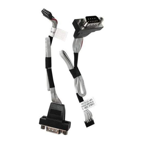
Two COM port adapters for P20U/P51U
The Shuttle XPC all-in-one P20U/P51U comes with two COM ports as
standard. Adding PCP21, two more COM ports will be available
which makes it a total of four serial COM ports (RS232) with Sub-D
connectors.
Feature Highlights
- 2x COM port adapter
Scope of
- 4x affixing screw (UNC 4-40 thread)
delivery
- Installation guide
External: Sub-D, 9-pin, male
Ports
Internal: 10-pin (2×5), female, 2 mm pitch
9-pin ribbon cable
Cable
Length: Approx. 21 cm
This accessory is compatible with the
Compatibility
Shuttle XPC all-in-one Barebone P20U and P51U.
Images for illustration purposes only.
Page 1 23 September 2019
w w w . s h u t t l e . e u
Product Specifications
Shuttle XPC accessory
before and after the installation of PCP21
S h u t t l e C o m p u t er Ha n d e l s G m bH
Fr it z -St r assm an n -St r . 5
25337 Elmsh orn | German y
PCP21
2x COM Port Adapter
Shuttle XPC all-in-one P20U
Tel. +49 (0) 4121-47 68 60
Fax +49 (0) 4121-47 69 00
sale s@sh u t t le.eu
Advertisement
Table of Contents

Related Manuals for Shuttle PCP21


Summary of Contents for Shuttle PCP21
- Page 1 Two COM port adapters for P20U/P51U 2x COM Port Adapter The Shuttle XPC all-in-one P20U/P51U comes with two COM ports as standard. Adding PCP21, two more COM ports will be available which makes it a total of four serial COM ports (RS232) with Sub-D connectors.
- Page 2 COM ports are to be installed. 4. Take the two COM port adapters PCP21 out of the packaging and remove the hexagon screws. Page 2 23 September 2019 S h u t t l e C o m p u t er Ha n d e l s G m bH Tel.
- Page 3 Product Specifications 5. Insert the two D-Sub connectors of the COM port adapter PCP21 in the corresponding openings and affix them with the supplied screws. 6. Connect the adapter cables to the "COM 3" and "COM 4" headers on the daughter board.
Need help?
Do you have a question about the PCP21 and is the answer not in the manual?
Questions and answers