Table of Contents
Advertisement
Quick Links
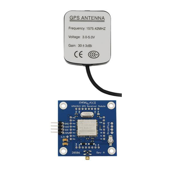
VPN1513 GPS Receiver Module (#28506)
The VPN1513 GPS Receiver Module provides a fully open source and customizable GPS Receiver solution
for your microcontroller projects. The VPN1513 uses a SiRF Star III chipset capable of tracking up to 20
satellites. The module supports both "raw" output mode for raw NMEA 0183 strings and the default
"smart" mode for specific user-selected data through a serial interface.
The VPN1513 GPS Receiver Module also features a Propeller co-processor for easy interface with any
BASIC Stamp 2 module. The Propeller is also fully reprogrammable and includes access to all 32 IO pins,
allowing the GPS Receiver Module to be easily transformed into a standalone device.
Features
Track up to 20 satellites
Fast satellite acquisition time
High tracking sensitivity (-159 dBm)
Navigation update rate of once per second (1 Hz)
Position accuracy of +/- 10 meters; 2D RMS +/- 5 meters
Velocity accuracy of +/- 0.1 meters per second
Maximum altitude of 18,000 meters
Propeller co-processor allows for easy transition to a
standalone device
Onboard LED for satellite acquisition feedback
9 ft. external antenna w/ MCX connector included
Battery-backed SRAM & RTC
Open source design
Key Specifications
Power requirements: 5 VDC @ 80 mA
Communication: Asynchronous serial, 9600 bps
Operating temperature: -22 to +185 °F (-30 to +85 °C)
Dimensions: 1.85 x 1.80 x 0.35 in (4.7 x 4.57 x 0.90 cm)
Application Ideas
Robotic navigation & positioning
Geocaching
Guidance systems
Automotive navigation
Fleet management
Copyright © Parallax Inc.
Web Site: www.parallax.com
Forums: forums.parallax.com
Sales: sales@parallax.com
Technical: support@parallax.com
VPN1513 GPS Receiver Module (#28506)
Office: (916) 624-8333
Fax: (916) 624-8003
Sales: (888) 512-1024
Tech Support: (888) 997-8267
v1.1 6/9/2011 Page 1 of 5
Advertisement
Table of Contents

Summary of Contents for Parallax VPN1513
- Page 1 The VPN1513 GPS Receiver Module provides a fully open source and customizable GPS Receiver solution for your microcontroller projects. The VPN1513 uses a SiRF Star III chipset capable of tracking up to 20 satellites. The module supports both “raw” output mode for raw NMEA 0183 strings and the default “smart”...
-
Page 2: Product Details
Satellite acquisition with this module is fast: ~47 seconds for a cold start, ~38 seconds for a warm start, and ~1 second for a hot start. The VPN1513 GPS Receiver Module has an onboard red indicator LED for easy visual feedback of satellite acquisition. - Page 3 Module Schematic Copyright © Parallax Inc. VPN1513 GPS Receiver Module (#28506) v1.1 6/9/2011 Page 3 of 5...
-
Page 4: Connection Diagrams
Connection Diagrams For use with the BASIC Stamp 2, example code available as a download from the VPN1513 GPS Receiver Module product page. Command Set By default, the VPN1513 GPS Receiver Module runs in “Smart Mode,” where the user can send serial messages to the GPS Module and have data returned to a microcontroller through the Propeller microcontroller co-processor. -
Page 5: Example Code
The VPN1513 GPS Receiver Module is compatible with the GPSDemoV1.1.bs2 code written by Joe Grand for the Parallax GPS Receiver Module (#28146), by changing the baud rate to 9600. This modified code can be downloaded from the VPN1513 GPS Receiver Module’s product page, visit www.parallax.com... -
Page 6: Product Information
Product Name: VPN1513 Product Description: VPN1513 is a compact, high performance, and low power consumption GPS engine board. It uses SiRF Star III chipset which can track up to 20 satellites at a time and perform fast TTFF in weak signal environments. -
Page 7: Technical Information
Accuracy Position: 10 meters, 2D RMS 5 meters, 2D RMS, WAAS enabled Velocity: 0.1 m/s Time: 1us synchronized to GPS time < 18,000 meter Maximum Altitude Maximum Velocity < 515 meter/second < 4G Maximum Acceleration Update Rate 1 Hz DGPS WAAS, EGNOS, MSAS Datum WGS-84... - Page 8 Module Pin Assignment: Application Circuit Pin NO. Pin Name Remark RF IN Connect to External Active Antenna. While external antenna is used. Ground. Ground. Ground. VBAT This is the battery backup input that powers the SRAM and RTC, The battery voltage should be between 2.0v and 5.0v. Ground.
- Page 9 Ground. Ground. Ground. Ground. TIMESYNC Pull-down via 4.7K to 10K. Ground. WAKE_UP Pull-down via 4.7K to 10K. Ground. Ground. This is the main transmits channel for outputting navigation and measurement data to user’s navigation software or user written software.Output TTL level, 0V ~ 2.85V. This is the main receive channel for receiving software commands to the engine board from SiRFdemo software or from user written software.
- Page 10 接地10K 电阻 GPS Active Antenna Specification (Recommendation) Frequency: 1575.42 + 2MHz Axial Ratio: 3 dB Typical output Impedance: 50ΩPolarization: RHCP Amplifier Gain: 18~22dB Typical Output VSWR: 2.0 Max. Noise Figure: 2.0 dB Max Antenna Input Voltage: 2.85V (Typ.) Dimensions...
-
Page 11: Recommended Layout Pad
Recommended Layout PAD... - Page 12 Tolerance : ±0.1mm VPN1513 Version 1.0 VPN1513 Application guideline Application Circuit GPS_3V3...
- Page 13 R1 4.7K~10K Recommend RESET Circuit GPS_3V3 ACTIVE LOW RESET INPUT R3 270R RESET...
- Page 14 The Specifications are subject to be changed without notice. Copyright © 2007, GlobalSat Technology. Page 9 of 27 GPS POWER VIN GPS_3V3 Layout Rule Do not routing the other signal or power trace under the engine board . * RF: This pin receives signal of GPS analog via external active antenna .It has to be a controlled impedance trace at 50ohm.
- Page 15 GND provides the ground for digital part. This is the main receive channel for receiving software commands to the engine board from SiRFdemo software or from user written software. For user’s application (not currently used). This is the main transmits channel for outputting navigation and measurement data to user’s navigation software or user written software.
- Page 16 BOOTSEL Set this pin to high for programming flash. VPN1513 Demo Kit Test Description Test Board Connection VPN1513 Demo Kit: Demo Kit JP1 (Male) Connection Test Board J5 (Female) Definition of Pin assignment JP1:...
- Page 17 Signal Name Signal Name Signal Name Signal Name nWakeup TIMESYNC TIMEMARK GPIO ECLK RESET BOOTSEL JP3: VBAT Test Software GPSinfo: Select COM Port & Baud Rate Press Start GPS...
- Page 18 SOFTWARE COMMAND NMEA Output Command GGA-Global Positioning System Fixed Data Table B-2 contains the values for the following example: $GPGGA,161229.487,3723.2475,N,12158.3416,W,1,07,1.0,9.0,M,,,,0000*18 Table B-2 GGA Data Format Name Example Units Description Message ID $GPGGA GGA protocol header UTC Time 161229.487 hhmmss.sss Latitude 3723.2475 ddmm.mmmm N/S Indicator...
-
Page 19: Gll-Geographic Position-Latitude/Longitude
Value Description Fix not available or invalid GPS SPS Mode, fix valid Differential GPS, SPS Mode , fix valid GPS PPS Mode, fix valid GLL-Geographic Position-Latitude/Longitude Table B-4 contains the values for the following example: $GPGLL,3723.2475,N,12158.3416,W,161229.487,A*2C Table B-4 GLL Data Format Name Example Units... - Page 20 GSV-GNSS Satellites in View Table B-8 contains the values for the following example: $GPGSV,2,1,07,07,79,048,42,02,51,062,43,26,36,256,42,27,27,138,42*71 $GPGSV,2,2,07,09,23,313,42,04,19,159,41,15,12,041,42*41 Table B-8 GSV Data Format Name Example Description Message ID $GPGSV GSV protocol header Number of Messages Range 1 to 3 Message Number1 Range 1 to 3 Satellites in View Satellite ID Channel 1(Range 1 to 32)
- Page 21 VTG-Course Over Ground and Ground Speed $GPVTG,309.62,T,,M,0.13,N,0.2,K*6E Name Example Units Description Message ID $GPVTG VTG protocol header Course 309.62 degrees Measured heading Reference True Course degrees Measured heading Reference Magnetic Speed 0.13 knots Measured horizontal speed Units Knots Speed Km/hr Measured horizontal speed Units Kilometers per hour...
- Page 22 **Checksum Field: The absolute value calculated by exclusive-OR the 8 data bits of each character in the Sentence,between, but excluding “$” and “*”. The hexadecimal value of the most significant and least significant 4 bits of the result are convertted to two ASCII characters (0-9,A-F) for transmission.
- Page 23 UINT32 <WeekNo> GPS Week Number UINT16 ( Week No and Time Of Week calculation from UTC time) Number of channels to use.1-12. If your CPU <chnlCount> throughput is not high enough, you could decrease needed throughput by reducing the number of active channels UBYTE <ResetCfg>...
- Page 24 communication parameters for PORT B are 9600 Baud, 8data bits, 0 stop bits, and no parity. If a DGPS receiver is used which has different communication parameters, use this command to allow the receiver to correctly decode the data. When a valid message is received, the parameters will be stored in battery backed SRAM and then the receiver will restart using the saved parameters.
- Page 25 $ PSRF103,<msg>,<mode>,<rate>,<cksumEnable>*C KSUM<CR><LF> <msg> 0=GGA,1=GLL,2=GSA,3=GSV,4=RMC,5=VTG <mode> 0=SetRate,1=Query <rate> Output every <rate>seconds, off=0,max=255 <cksumEnable> 0=disable Checksum,1=Enable checksum for specified message Example 1: Query the GGA message with checksum enabled $PSRF103,00,01,00,01*25 Example 2: Enable VTG message for a 1Hz constant output with checksum enabled $PSRF103,05,00,01,01*20Example 3: Disable VTG message $...
- Page 26 acquisition. Format: $PSRF104,<Lat>,<Lon>,<Alt>,<ClkOffset>,<TimeOfWeek>,<WeekNo>, <ChannelCount>, <ResetCfg>*CKSUM<CR><LF> <Lat> Latitude position, assumed positive north of equator and negative south of equator float, possibly signed <Lon> Longitude position, it is assumed positive east of Greenwich and negative west of Greenwich Float, possibly signed <Alt> Altitude position float, possibly signed <ClkOffset>...
- Page 27 0×01=Data Valid warm/hot starts=1 0×02=clear ephemeris warm start=1 0×04=clear memory. Cold start=1 UBYTE Example: Start using known $ position and time. PSRF104,37.3875111,-121.97232,0,96000 ,237759,922,12,3*37 F). Development Data On/Off ID:105 Switch Development Data Messages On/Off Use this command to enable development debug information if you are having trouble getting commands accepted.
- Page 28 datum. The default datum is WGS 84 (World Geodetic System 1984) which provides a worldwide common grid system that may be translated into local coordinate systems or map datums. (Local map datums are a best fit to the local shape of the earth and not valid worldwide.) Examples: Datum select TOKYO_MEAN $PSRF106,178*32...
Need help?
Do you have a question about the VPN1513 and is the answer not in the manual?
Questions and answers