Table of Contents
Advertisement
Quick Links
Advertisement
Table of Contents

Related Manuals for Optical Systems Design OSD9003

Summary of Contents for Optical Systems Design OSD9003
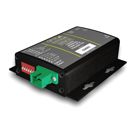
- Page 1 OPERATOR MANUAL OSD9003/OSD9004 WIDEBAND FIBEROPTIC RF LINK...
- Page 3 EXCLUSIONS ............................15 FIGURE 1: OSD9003/OSD9004 MOUNTING DIMENSIONS.............. 7 FIGURE 2: OSD9003/OSD9004 FRONT/REAR PANELS ..............7 FIGURE 3: OSD9003/9004 POWER SUPPLY CONNECTIONS ............8 FIGURE 4: OSD9003 SWITCH SETTINGS ................... 9 FIGURE 5: OSD9003 LED INDICATORS ................... 12 FIGURE 6: OSD9004 LED INDICATOR ..................... 12 FIGURE 7: OSD9003 CONNECTIONS ....................
- Page 4 Both the OSD9003 and OSD9004 are packaged in a very small, rugged standalone enclosure operating from a wide range of input power supply voltages, allowing totally non-critical powering.
-
Page 5: Technical Specifications
OPTICAL SYSTEMS DESIGN TECHNICAL SPECIFICATIONS TABLE 1: OSD9003 TECHNICAL SPECIFICATIONS SPECIFICATION PERFORMANCE 1310 ±5nm nominal. Also available in all 18 CWDM wavelengths (1270-1610)nm Operating Wavelength Optical Output Power +3.0 ±1.0dBm SC/APC (FC/APC is optional) Optical Connector >45dB Optical Return Loss... -
Page 6: Installation
OSD9004 input is less than +3dBm or damage to the unit may occur. The OSD9003 can launch optical power as high as +7dBm. In situations where optical path attenuation is not high enough, a fixed optical attenuator must be used to reduce optical power at the OSD9004 receiver input to less than +3dBm. - Page 7 OPTICAL SYSTEMS DESIGN OSD9003/OSD9004 DRAWINGS AND DIMENSIONS The OSD9003/OSD9004 standalone module is designed to be mounted on an even surface and to be secured by means of M4 or smaller screws. 25.6 25.6 DETAIL A Ø8.5 R2.1 R2.1 DETAIL A 83.4...
- Page 8 When an alarm occurs, the output goes into a high impedance state. When power to the OSD9003 unit is switched off or the laser current monitor indicates laser fail mode Pin 3 becomes open circuit. The unit’s monitoring circuit connects Pin3 to Pin2 (circuit ground) when there is no fault.
- Page 9 OPTICAL SYSTEMS DESIGN 2.5.3 OSD9003/OSD9004 SWITCH SETTINGS FIGURE 4: OSD9003 SWITCH SETTINGS OSD9003 Settings In Manual Mode the RF attenuation is controlled by dip switches (SW1-SW5). Each toggle switch changes the Input RF attenuation level by 1,2,4,8 and 16dB respectively. Toggling the position on any switch is the sum of the attenuated amount ie switch 1 (16dB) and 3 (4dB) enabled will provide an attenuation of 20dB.
- Page 10 RF output power manually or alternatively can be set to automatic gain control by setting switch 6 to the on position (up). In automatic gain control mode the unit maintains constant output level over the optical range of 15dB. DOC ID: 10111701 PAGE 10 OSD9003/OSD9004 OPERATOR MANUAL...
- Page 11 SYSTEM SETTING RECOMMENDATIONS The RF output power can be set to provide system unity gain if there is sufficient received optical power. Table 6 shows what levels to expect in OSD9003/9004 system TABLE 6: TYPICAL LEVELS FOR SINGLE CARRIER OSD9003...
- Page 12 OPTICAL SYSTEMS DESIGN 2.5.5 OSD9003 LED INDICATORS FIGURE 5: OSD9003 LED INDICATORS TABLE 7: OSD9003 LED INDICATOR FUNCTION LED Indicator LED Colour Input RF Power (dBm) Red (blinking) > +20 Green LED ON > +10 Green LED ON > 0 Green LED ON >...
- Page 13 OPTICAL SYSTEMS DESIGN 2.5.7 OSD9003 CONNECTIONS Power Alarm Optical Fiber SMA RF Cable Output Input FIGURE 7: OSD9003 CONNECTIONS 2.5.8 OSD9004 CONNECTIONS Power Alarm Optical Fiber SMA RF Cable Input Output FIGURE 8: OSD9004 CONNECTIONS DOC ID: 10111701 PAGE 13...
-
Page 14: External Inspection
OPTICAL SYSTEMS DESIGN 3 MAINTENANCE INTRODUCTION The following section outlines the fault-finding procedure for the OSD9003/OSD9004 modems. Please take note of the following: Personnel without appropriate training should not attempt any maintenance except that outlined ▲ below. If further maintenance is attempted you are warned that every care should be taken to ensure that ▲... -
Page 15: Warranty Period
For warranty period, please contact your local OSD distributor. REPAIRS Optical Systems Design reserves the right to repair or replace faulty modules/units. Please obtain a “Return Material Authorisation” (RMA) form and number before returning goods. Goods must be returned in adequate packing material to Optical Systems Design, Warriewood or its nominated authorised representative, for all repairs. - Page 16 OPTIC L Optical Systems Design Pty. Ltd. 7/1 Vuko Pl. Warriewood 2102 SYSTEMS P.O. Box 891 Mona Vale N.S.W. Australia 2103 Telephone: +61 2 9913 8540 DESIGN Facsimile: +61 2 9913 8735 Email: sales@osd.com.au Web Site: www.osd.com.au PTY LTD A.B.N. 83 003 020 504...
Need help?
Do you have a question about the OSD9003 and is the answer not in the manual?
Questions and answers