Table of Contents
Advertisement
Advertisement
Table of Contents

Subscribe to Our Youtube Channel
Related Manuals for Zurich ZR4

Summary of Contents for Zurich ZR4
-
Page 2: Table Of Contents
Table of Contents SAFETY PRECAUTIONS IMPORTANT SAFETY INFORMATION ........ABOUT THE VEHICLES COVERED ............. CONTROLS AND INDICATORS ..........DISPLAY FUNCTIONS ............DISPLAY AND SETTINGS ............ONBOARD DIAGNOSTICS OBD2 TERMINOLOGY ............DIAGNOSTIC TROUBLE CODES (DTCs) ......OBD2 MONITORS ..............PREPARATION FOR TESTING BEFORE YOU BEGIN .............. -
Page 3: Safety Precautions
Safety Precautions IMPORTANT SAFETY INFORMATION IMPORTANT SAFETY INFORMATION Read all safety warnings and all instructions. Failure to follow the warnings and instructions may result in electric shock, fire and/or serious injury. Save all warnings and instructions for future reference. 1. Operating a vehicle indoors CAN KILL YOU IN MINUTES. Engine exhaust contains carbon monoxide. -
Page 4: About The
About the Code Reader VEHICLES COVERED VEHICLES COVERED The Code Reader is designed to work on all OBD2 compliant vehicles. All 1996 and newer vehicles (cars and light trucks) sold in the United States are OBD2 compliant. This includes all Domestic, Asian and European vehicles. -
Page 5: Controls And Indicators
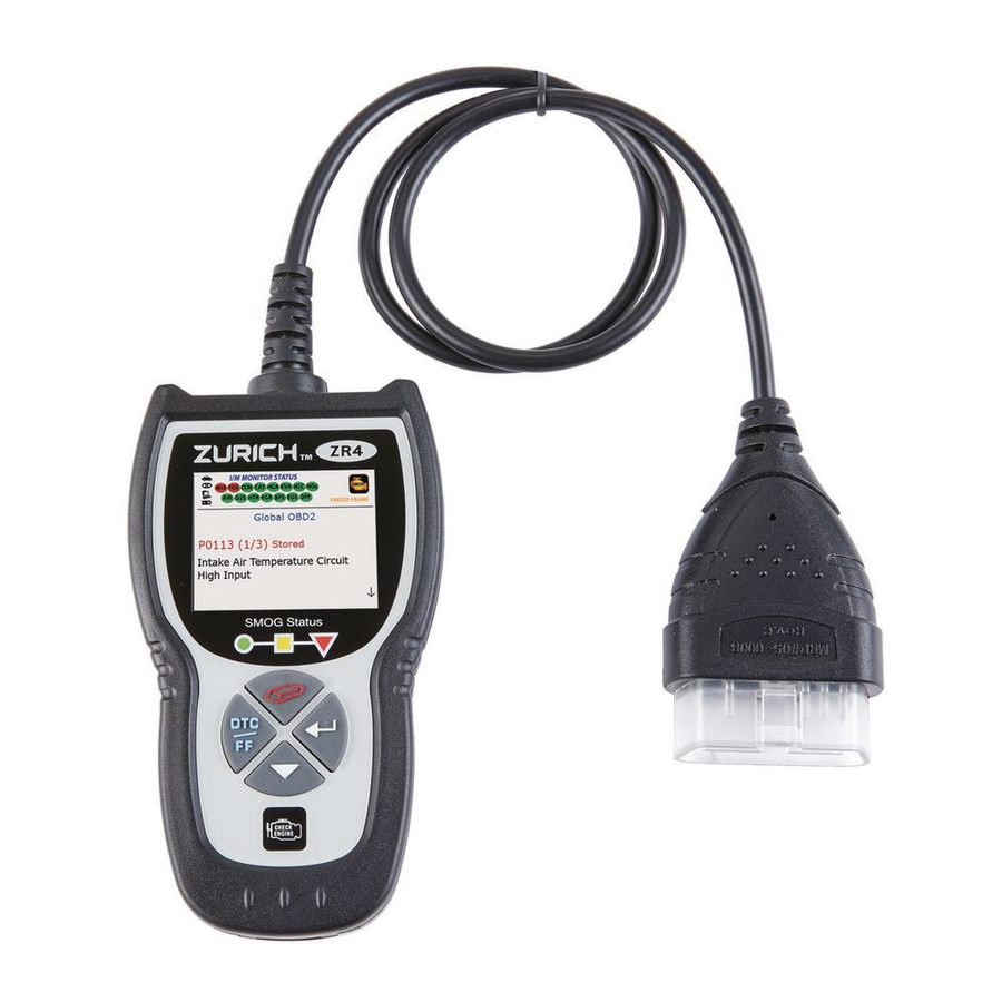
About the Code Reader CONTROLS AND INDICATORS CONTROLS AND INDICATORS Figure 1. Controls and Indicators See Figure 1 for the locations of items 1 through 9, below. ERASE button - Erases Diagnostic Trouble Codes (DTCs) and "Freeze Frame" data from your vehicle's computer, and resets Monitor status. -
Page 6: Display Functions
About the Code Reader DISPLAY FUNCTIONS 6. YELLOW LED - Indicates there is a possible problem. A “Pending” DTC is present and/or some of the vehicle's emission monitors have not run their diagnostic testing. 7. RED LED - Indicates there is a problem in one or more of the vehicle's systems. -
Page 7: Display And Settings
About the Code Reader DISPLAY AND SETTINGS Link icon - Indicates whether or not the Code Reader is com- municating (linked) with the vehicle's on-board computer. When visible, the Code Reader is communicating with the computer. If the Link icon is not visible, the Code Reader is not communicating with the computer. - Page 8 About the Code Reader DISPLAY AND SETTINGS 2. When the desired display language is selected, press the ENTER button to confirm your selection. The Unit of Measurement screen displays. 3. Use the DOWN button to highlight the desired unit of measurement. 4.
-
Page 9: Onboard Diagnostics
Onboard Diagnostics OBD2 TERMINOLOGY OBD2 TERMINOLOGY The following terms and their definitions are related to OBD2 systems. Read and reference this list as needed to aid in the understanding of OBD2 systems. Powertrain Control Module (PCM) - The PCM is the OBD2 accepted term for the vehicle’s “on-board computer.”... -
Page 10: Diagnostic Trouble Codes (Dtcs)
Onboard Diagnostics DIAGNOSTIC TROUBLE CODES (DTCs) OBD2 Drive Cycle - An OBD2 Drive Cycle is an extended set of driving procedures that takes into consideration the various types of driving conditions encountered in real life. These conditions may include starting the vehicle when it is cold, driving the vehicle at a steady speed (cruising), accelerating, etc. - Page 11 Onboard Diagnostics DIAGNOSTIC TROUBLE CODES (DTCs) Generic DTCs are codes that are used by all vehicle manu- facturers. The standards for generic DTCs, as well as their definitions, are set by the Society of Automotive Engineers (SAE). Manufacturer-Specific DTCs are codes that are controlled by the vehicle manufacturers.
- Page 12 Onboard Diagnostics DIAGNOSTIC TROUBLE CODES (DTCs) DTCs and MIL Status When the vehicle’s on-board computer detects a failure in an emissions-related component or system, the computer’s internal diagnostic program assigns a diagnostic trouble code (DTC) that points to the system (and subsystem) where the fault was found.
-
Page 13: Obd2 Monitors
Onboard Diagnostics OBD2 MONITORS If the conditions that caused the MIL to light are no longer present for the next three trips in a row, the computer automatically turns the MIL “Off” if no other emissions-related faults are present. However, the DTCs remain in the computer’s memory as a history code for 40 warm-up cycles (80 warm-up cycles for fuel and misfire faults). - Page 14 Onboard Diagnostics OBD2 MONITORS Oxygen Sensor Monitor Oxygen Sensor Heater Monitor Catalyst Monitor Heated Catalyst Monitor EGR System Monitor EVAP System Monitor Secondary Air System Monitor The following Monitors will be standard beginning in 2010. The majority of vehicles produced before this time will not support these Monitors NMHC Monitor NOx Adsorber Monitor...
- Page 15 Onboard Diagnostics OBD2 MONITORS Name of Monitor Comprehensive Continuous Component Monitor Misfire Monitor 3 - similar Continuous (Type 1 and 3) conditions Misfire Monitor 3 - similar Continuous (Type 2) conditions Fuel System Monitor 3 - similar Continuous 1 or 2 conditions Catalytic Converter Once per...
-
Page 16: Preparation For Testing Before You Begin
Preparation for Testing BEFORE YOU BEGIN BEFORE YOU BEGIN Fix any known mechanical problems before performing any test. See your vehicle's service manual or a mechanic for more information. Check the following areas before starting any test: Check the engine oil, power steering fluid, transmission fluid (if applicable), engine coolant and other fluids for proper levels. -
Page 17: Using The Code Reader Code Retrieval Procedure
Using the Code Reader CODE RETRIEVAL PROCEDURE CODE RETRIEVAL PROCEDURE Never replace a part based only on the DTC definition. Each DTC has a set of testing procedures, instructions and flow charts that must be followed to confirm the location of the problem. This information is found in the vehicle's service manual. - Page 18 Using the Code Reader CODE RETRIEVAL PROCEDURE 6. The Code Reader will automatically start a check of the vehicle’s computer determine which type communication protocol it is using. When the Code Reader identifies the computer’s communication protocol, a communication link is established. If the Code Reader fails to link to the vehicle’s computer a “Communi- cation Error”...
- Page 19 Using the Code Reader CODE RETRIEVAL PROCEDURE 8. To read the display: Refer to DISPLAY FUNCTIONS on page 4 for a description of display elements. A visible icon indicates that the Code Reader is being powered through the vehicle’s DLC connector. A visible icon indicates that the Code Reader is linked to (communicating with) the vehicle’s computer.
- Page 20 Using the Code Reader CODE RETRIEVAL PROCEDURE Green LED – Indicates that all engine systems “OK” operating normally. All monitors supported by the vehicle have run performed their diagnostic testing, and no trouble codes are present. All Monitor icons will be solid.
- Page 21 Using the Code Reader CODE RETRIEVAL PROCEDURE DTC’s that start with “P1” and some “P3” are Manufacturer specific codes and their code definitions vary with each vehicle manufacturer. When a Manufacturer specific retrieved, the LCD display shows a list of vehicle manufacturers. Use the DOWN button, as necessary, to highlight the appropriate manufac-...
-
Page 22: Erasing Diagnostic Trouble Codes (Dtcs)
Using the Code Reader ERASING DIAGNOSTIC TROUBLE CODES (DTCs) If DTC’s were retrieved and you are going to perform the repairs yourself, proceed by consulting the Vehicle’s Service Repair Manual for testing instructions, testing procedures, and flow charts related to retrieved code(s). ERASING DIAGNOSTIC TROUBLE CODES (DTCs) When the Code Reader’s ERASE function is used to erase the DTCs from the vehicle's on-board computer, "Freeze... - Page 23 Using the Code Reader ERASING DIAGNOSTIC TROUBLE CODES (DTCs) 4. A “One moment please…” message displays while the erase function is in progress. If the engine is running, an advisory dialog displays. Turn the engine off, place the ignition in the ON position, then press the ERASE button to continue.
-
Page 24: Additional Functions
Additional Functions THE MAIN MENU - EVAP TEST THE MAIN MENU In addition to retrieving Diagnostic Trouble Codes (DTCs), you can use the Code Reader to perform additional diagnostic tests, to view diagnostic and vehicle information stored in your vehicle's on-board computer, and to configure the Code Reader for your particular needs. - Page 25 Additional Functions VIEWING VEHICLE INFORMATION Retrieving Vehicle ID Information The Vehicle ID function is applicable to model year 2000 and newer OBD2-compliant vehicles. The Code Reader can retrieve a list of information (provided by the vehicle manufacturer), unique to the vehicle under test, from the vehicle's on-board computer.
- Page 26 Additional Functions VIEWING VEHICLE INFORMATION 1. While linked to the vehicle, press and hold the ENTER button. The Main Menu displays. 2. Use button, DOWN necessary, highlight Vehicle Information, then press the ENTER button. Vehicle Information menu displays. 3. Use button, DOWN necessary,...
-
Page 27: Evap Test
Additional Functions VIEWING VEHICLE INFORMATION Vehicle Information menu displays. 3. Use button, DOWN necessary, to highlight IPT, then press the ENTER button. 4. When the retrieved process is completed, In-use Performance Tracking statistics for monitors supported by the vehicle under test are shown on the Code Reader’s display. -
Page 28: Viewing Monitor Icon Descriptions
Additional Functions EVAP TEST 3. When the EVAP leak test has been initiated by the vehicle's on-board computer, confirmation message shows on the Code Reader's display. Press the ENTER button to return to the Main Menu. VIEWING MONITOR ICON DESCRIPTIONS The I/M MONITOR STATUS icons on the Code Reader’s LCD display provide an indication of the “Completed / Not Complete”... -
Page 29: Adjustments, Settings And Language
Additional Functions ADJUSTMENTS, SETTINGS AND LANGUAGE 2. When you have finished viewing the LED definitions, press the button to return to the Main Menu. ENTER ADJUSTMENTS, SETTINGS AND LANGUAGE Selecting the Display Language 1. Use the DOWN button, as neces- sary, to highlight Language Selection in the Main Menu, then press the button. - Page 30 Additional Functions ADJUSTMENTS, SETTINGS AND LANGUAGE The Audible Tone screen displays. 2. Use the DOWN button, as neces- sary, to highlight On or Off as desired. 3. When the desired option is selected, press the ENTER button to save your changes and return to the Main Menu.
-
Page 31: Obd Updater
Additional Functions OBD UPDATER / TROUBLESHOOTING Setting the Unit of Measurement 1. Use the DOWN button, as neces- sary, to highlight Unit of Measurement in the Main Menu, then press the ENTER button. 2. Use the DOWN button, as neces- sary, to highlight the desired unit of measurement. -
Page 32: Limited 90 Day Warranty
Warranty and Servicing LIMITED 90 DAY WARRANTY Harbor Freight Tools Co. makes every effort to assure that its products meet high quality and durability standards, and warrants to the original purchaser that this product is free from defects in materials and workmanship for the period of 90 days from the date of purchase. - Page 33 63808...
Need help?
Do you have a question about the ZR4 and is the answer not in the manual?
Questions and answers
How can I get a paper manual sent to me
The context does not mention a way to request a paper manual for the Zurich ZR4. However, it explains that you can download the full manual or Quick Start Guide by clicking on the tool, scrolling to the "User Manual" or "Quick Start Guide" tab, and selecting the option to download.
This answer is automatically generated
What's the hook up on the bottom of the Zurich zr4s reader?
The Zurich ZR4S OBD2 code reader has a connector that plugs into the vehicle's OBD2 port. The hookup on the bottom of the reader is designed to match the OBD2 port in only one direction, ensuring proper connection for reading diagnostic trouble codes (DTCs) and other vehicle data.
This answer is automatically generated
what do the codes mean
I need this one pece
does it have abs and shows which wheel speed sensor went bad,?