Advertisement
Operation and Installation Instructions for FloodMaster Water
Heater Leak Detection larm/Shutoff Systems – Model FM-094
The FM-094 series of Feed Water (Water Heater) Leak Detection and Shut Off Systems is designed
to monitor and respond immediately to water leaks. When a sensor comes in contact with as little as
1/16th of an inch of water (or any other conductive liquid), it will automatically sound an audible alarm
and close the valve to shut down the water feed line, thus mitigating damage caused by an undetected
water leak. The unit also provides output signal capabilities (SPDT Relay Output Contact) for connection
to a home security panel or for use with an appropriate relay to control a secondary device, such as
a pump.
Output signal connections:
Normally Closed Circuit – Terminal Pins 3 & 4
Normally Open Circuit – Terminal Pins 4 & 5
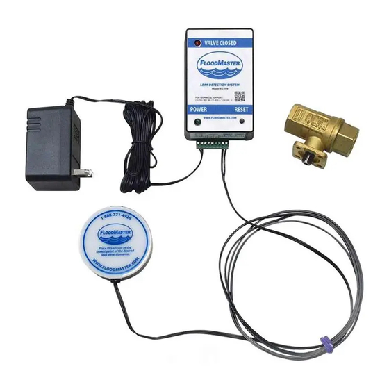
The kit includes the receiver with on-board audible alarm, a full port lead free (NSF/ NSI 61 nnex G) shut-off valve, 110 V C power supply, leak detection
sensor and a screw driver. dditional sensors can be added where a wider area of leak detection is required (additional sensors sold separately).
Operation:
In the event the system activates, locate the source of the leak, remove the sensor from the water and dry the metal contacts on the bottom. Correct the
problem causing the leak and replace the sensor in the desired leak detection location once again as required. Press and release the reset button on the
receiver to open the valve and begin the flow of water again. The green Power indicator light on the receiver will flash once to confirm the reset.
Installation Instructions:
1. Turn off the water supply feed line to the water heater.
2. Thread the valve body into the feed water line after the manual shut-off. pply pipe sealant or Teflon
to the NPT threads and tighten.
3. The receiver connector comes pre-wired with basic connections to the power supply and the sensor. Using the
screwdriver provided, make any additional electrical connections as may be desired for output contacts or
additional sensors per the diagram provided. (Note: additional sensors can be connected to either 6 & 7 or
8 & 9, as wiring space allows).
• Snap the terminal wiring block into the receiver housing at the mating slot provided.
4. Secure the valve body in one hand and snap the receiver into place on the valve body mounting pad.
(Note: Improper alignment of the valve stem may interfere with proper receiver mounting. If any resistance is encountered, confirm the witness mark on
the valve stem is in alignment with the ports of the valve. Use an appropriate hand tool, such as pliers, to clamp down on the valve stem and turn in the
appropriate direction until the desired position is achieved).
5. Plug the power transformer into a 120V C wall outlet; the green Power indicator light on the receiver will turn on.
6. Function Test the system as follows:
a. Place the sensor on a wet paper towel.
b. The audible alarm will sound and the valve will rotate to the closed position.
c. The red Valve Closed LED will turn on when the valve is completely closed (approximately 45-second cycle time). Open a hot water faucet and
inspect for absence of water flow. There should be no flow.
d. Remove the sensor puck from the paper towel, dry the contact points and place the sensor puck back in the desired location on the floor.
e. Press and release the Reset Button on the receiver to open the valve and begin the flow of water again (approximately 45 seconds to fully open
position). The green Power indicator light will flash once to indicate the reset process has begun.
f. Open a hot water faucet and inspect for water flow.
Maintenance:
We recommend an annual test of the unit to ensure proper function. See unction Test instructions above. t a minimum, users should exercise (press and
release) the reset button on the receiver annually to ensure correct operation and to maintain product warranty status.
Emergency Manual Operation of the Valve:
The unit is equipped with an emergency feature for the manual rotation of the valve. This can be accomplished by disengaging the actuator from the valve
and manually changing the valve to open or closed as follows:
1. Unplug the unit from the 120V C wall outlet.
2. Stabilize the water feed line by grabbing it in one hand near the valve, while grasping the actuator housing in the other hand, pull the actuator housing
away from the water feed line.
3. Using an appropriate hand tool, such as a pliers, clamp down on valve stem and turn in the appropriate direction until the desired position is achieved.
Note the top of the stem is slotted to indicate valve position (in line with water flow would indicate open valve; slot across water line would indicate
closed valve).
4. Before remounting the actuator, return the valve to the original position prior to the manual rotation.
5. Remount the actuator and plug into 120 V C wall outlet.
6. Test for correct operation per the unction Test listed above.
FloodMaster
Email: info@floodmaster.com
nstallation Manual
( loodMaster recommends that installations be completed by a licensed plumber to ensure that all local code requirements are followed).
®
, LLC
•
27 Business Park Drive, Branford, CT 06405
•
www.FloodMaster.com
®
tape
•
Tel: 203-488-4477
•
888-771-4929
FM-094
Sensor
Sensor
•
Fax: 203-481-5036
ECN# 6622, 11/2013, MF-088, REV A
Advertisement
Table of Contents

Summary of Contents for FloodMaster FM-094 Series
- Page 1 Heater Leak Detection larm/Shutoff Systems – Model FM-094 The FM-094 series of Feed Water (Water Heater) Leak Detection and Shut Off Systems is designed to monitor and respond immediately to water leaks. When a sensor comes in contact with as little as...
- Page 2 FM-094 QUICK-ST RT GUIDE Water Heater Leak Detection + utomatic Shut-Off System Manually shut off the water feed line to the water heater. Install the FloodMaster shut-off valve on the feed line. Make any additional wiring connections. Wiring Diagram Sensor Sensor Mount the actuator to the valve.
Need help?
Do you have a question about the FM-094 Series and is the answer not in the manual?
Questions and answers
Your images show the receiver unit mounted with the long axis vertical on a vertical water line. Where the water line is coming out of the wall horizontal near the ceiling, can the receiver mount with the long axis horizontal and the front face vertical.