
Summary of Contents for HORITA SCT-50
-
Page 1: General Chapter
HORITA SCT-50 Serial Control Titler USER MANUAL For Models SCT-50, RM-50/SCT, SR-50/SCT Doc. 071550 Rev. D (C) Copyright 2014 P.O. Box 3993, Mission Viejo, CA 92690 (949) 489-0240 www.horita.com... -
Page 2: Features Chapter
HORITA CO., INC, P.O. Box 3993, Mission Viejo, CA 92690. HORITA CO., INC makes no warranties with respect to this documentation and disclaims any warranties of merchantability or fitness of the SCT-50 for a particular purpose or application. -
Page 3: Table Of Contents
CHAPTER 1 2 FEATURES CHAPTER 2 SCT-50 Umit SCT-50 GMAN Software 3 CONNECTING CHAPTER 3 Figure 3.1, SCT-50 Serial Port Wiring 4 OPERATING CHAPTER 4 Power Up Mode Flow Diagram Explanation Figure 4-1, SCT-50 Mode Flow Diagram LED Operation Entering and Exiting the Setup Menus... -
Page 4: Sct-50 Umit
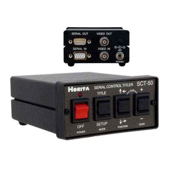
NTSC or PAL composite video images from TV cameras, video recorders, computers, etc. The SCT-50 can insert up to nine lines of twenty characters each into the video image to add source ID information such as camera number and location for security applications, add measurement data during video data collection, or to simply add text in other video monitoring and display situations. -
Page 5: Sct-50 Gman Software
You can use any standard male-to-female, one-to-one DB9 cable 4. If you are connecting more than one SCT-50 to the serial port, use another DB9 cable to connect between units. You can also purchase special extra short 1' DB9 SCT-50 cables from HORITA. Routing of the serial cables to and between the SCT-50 units themselves can be in any order. -
Page 6: Power Up
SCT-50 is powered up. When the SCT-50 is initially powered up, it operates in the "display" mode to display the time and date and any user source ID information entered. The POSITION and CHAR switches operate to provide quick and convenient control of the display's... -
Page 7: Mode Flow Diagram Explanation
The SCT-50 can be operated locally using the front panel switches or from both the switches and the PC to enter text and setup information. Operation is first described for entering and changing "setup" data, then entering and editing text using the SCT-50 front panel switches. -
Page 8: Selecting Different Setup Menu Items
SCT-50 for serial communications with PC. Note that setting the SCT-50 address to "00" places it in the "promiscuous" mode which enables it to respond to all information sent via the serial port from the computer, ignoring any specific SCT-50 address. -
Page 9: Display Setup Menu
Y = Reset SCT-50 system System reset initializes all variable data in the SCT-50 to default values. A hardware selected SYSTEM RESET function is accessible by powering up the SCT-50 while holding the MODE switch in the "SETUP" position, then releasing it. -
Page 10: Time Setup Menu
When the starting position of the time display is changed via actuating the CHAR switch while the "START POSITION" menu item is selected, the SCT-50 temporarily exits the TIME SETUP menu to show the display screen. Further actuation of the CHAR switch moves the position of the time display on a character by character basis in a serpentine fashion so that you can observe its actual position within your normal video display. -
Page 11: Date Setup Menu
When the starting position of the date display is changed via actuating the CHAR switch while the "START POSITION" menu item is selected, the SCT-50 temporarily exits the DATE SETUP menu to show the display screen. Further actuation of the CHAR... -
Page 12: Selecting Local Titling Mode And Entering
4.11 Selecting Local Titling Mode and Entering and Editing Data. To select the text entry TITLE mode for the SCT-50, actuate and release the MODE switch to TITLE until the front panel LED flashes at about once per second and the screen displays a flashing cursor. The flashing cursor shows the position of where the next character will be entered. - Page 13 These switches operate in much the same manner as those found on the simple titlers on many camcorders. The POSITION "arrow" switches select a character's position, and the CHAR "+/-" switches select a particular character from various numeric, alpha, punctuation, and math symbols. You can actuate a switch for a single selection at a time, or hold it down for 2-seconds and cause automatic and rapid selection.
-
Page 14: Inserting Spaces And Deleting Characters
"00". Broadcast mode addresses all SCT-50 regardless of their individual unique addresses. If an individual SCT-50's address is set to "00", that SCT-50 will receive and display all text and commands sent from the PC for... -
Page 15: Serial Communications Check
NOTE: At 9600 baud the number of SCT-50 units that can be operated by a single serial port is at least 100 units. Also note that there are active RS-232 repeater circuits in each SCT-50 and this requires that power must be applied to all of the SCT-50 units that are connected together and operating from a single PC serial port so that the serial data can proceed from unit to unit. -
Page 16: Serial Command Set
5.5 Serial Command Set The following list shows all of the serial commands and data that can be sent to operate an SCT-50 via its serial port. As can be seen, an address requires two (ASCII) bytes of data, a command requires two bytes, and any subsequent data itself can be none or one or more bytes. -
Page 17: Character Set And Ascii Codes
The serial data to be sent to the SCT-50 is: Escape, Address, Command. As described earlier, the DISPLAY OFF command is decimal "08", and assuming the address of the SCT-50 is set to "01", the sequence of serial data sent to the SCT-50 to turn the... -
Page 18: Software Programming Examples
Check that the SCT-50 LED blinks off when serial data is sent. c. If the LED blinks off, make sure that the SCT-50 address is setup correctly and has been sent out by the PC. A quick test is to enter address "00"... -
Page 19: Horizontal Size Adjustment
1. Connect a 1-volt P-P video sweep signal to VIDEO IN and a waveform monitor or oscilloscope to VIDEO OUT. Make sure the video output is terminated. 2. Adjust VID LEVEL control R23 for a 1-volt P-P output level (unity gain) 3. Adjust C25 for flattest frequency response out to 5 MHz. 4. Re-assemble the SCT-50... - Page 20 SPECIFICATIONS Power Operation 9-to-14V DC, 150 milliamperes Connector 3.5mm mini phone jack, center positive AC Adapter 9 Volt, 500 milliamperes Video Standard NTSC 525/60 (RS170A), PAL 625/50 Level 1-Volt p-p Impedance 75-Ohm Connectors Video In/Out Serial In DB9 Female Serial Out DB9 Male Switches and Controls Power...
Need help?
Do you have a question about the SCT-50 and is the answer not in the manual?
Questions and answers