Table of Contents

Subscribe to Our Youtube Channel
Related Manuals for CS Instruments VA 520

Summary of Contents for CS Instruments VA 520
- Page 1 EN – English Instruction manual Consumption counter VA 520 with Display, 4 ... 20 mA and pulse output (galv. isolated) Stationary Flow and consumption measurement for compressed air and gases VA 520 English V1.06 Page 1 of 30...
-
Page 2: Foreword
Foreword Dear customer, thank you very much for deciding in favour of the VA 520. Please read this installation and operation manual carefully before mounting and initiating the device and follow our advice. A riskless operation and a correct functioning of the... -
Page 3: Table Of Contents
Values Register (1001 …1500) ................21 8.3.2.2 8.3.3 Pulse /Alarm ........................23 8.3.3.1 Pulse output ......................23 8.3.4 User Setup ........................24 8.3.5 Advanced ......................... 24 8.3.6 4 -20mA ........................... 25 8.3.7 VA 520 Info ........................27 VA 520 English V1.06 Page 3 of 30... - Page 4 Inhaltsverzeichnis Maintenance .........................28 Cleaning of the sensor head ..................28 Re-Calibration ......................28 Spare parts and repair ....................28 Calibration .........................28 Warranty ........................29 VA 520 English V1.06 Page 4 of 30...
-
Page 5: Safety Instructions
We are also not liable for consequential damage resulting from the delivery, capability or use of this device. We offer you to take back the instruments of the instruments family VA 520 which you would like to dispose of. -
Page 6: Instruments Description
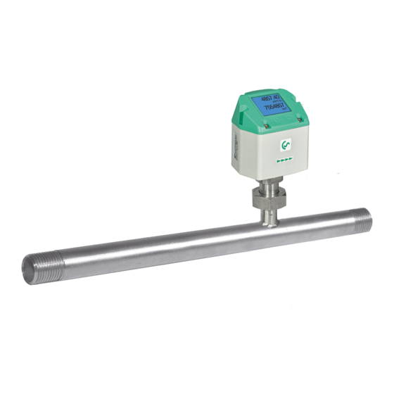
2 Instruments description The VA 520 is a compact consumption counter for compressed air and gases. Special features: - Optimum accuracy due to compact design - Integrated in- and outlet section - Less flow due to measuring section - Integrated Display, Units free selectable. m³/h, m³/min, l/min, l/s, kg/h, kg/min, kg/s, cfm - Modbus RTU (RS485) Interface - Analogue output 4..20mA... -
Page 7: Technical Data
4… 20 mA = VA 520 with integrated 1" meas. section 0...290 m³/h 4… 20 mA = VA 520 with integrated 1 1/4" meas. section 0...530 m³/h 4… 20 mA = VA 520 with integrated 1 1/2" meas. section 0...730 m³/h 4…... -
Page 8: Installation Description
Attention: The measuring sections of VA 520 consumption counters with 1 1/2" and 2" measuring section have reduced inlet and outlet sections. Please take into consideration the recommended inlet and outlet sections. -
Page 9: Displayhead Position
For this purpose the 6 fastening screws are to be released and the displayhead rotated 180°. Caution: It must be ensured that the connection plugs are still plugged and the gasket is installed correctly. VA 520 English V1.06 Page 9 of 30... -
Page 10: Flow Measuring Ranges
DVGW admission, however, it can be used for measurements in natural gas. A DVGW admission is not mandatory. The area outside the pipeline (ambient area of the sensor) must not be an explosive area. VA 520 English V1.06 Page 10 of 30... -
Page 11: Dimensions
VA 520 with integrated 1" meas. section 0...290 m³/h 4… 20 mA = 0695 1526 0695 0526 VA 520 with integrated 1 1/4" meas. section 0...530 m³/h 4… 20 mA = 0695 1524 0695 0524 VA 520 with integrated 1 1/2" meas. section 0...730 m³/h... -
Page 12: With Measurement Section And Flange (Material Stainless Steel 1.4404)
0695 2523 VA 520 with integrated 1" meas. section with weld neck flange 0695 2526 VA 520 with integrated 1 1/4" meas. section with weld neck flange 4… 20 mA = 0...530 m³/h 0695 2524 VA 520 with integrated 1 1/2" meas. section with weld neck flange 4… 20 mA = 0...730 m³/h 4…... -
Page 13: Electrical Wiring / Displayhead Position
DIP Switch to “On”. It must be ensured that the connection plugs are still plugged and the gasket is installed correctly, see also chapter 4.5. Alternatively, a 120R resistor can be installed in the plug between pin 2 and pin VA 520 English V1.06 Page 13 of 30... -
Page 14: Operation
“Enter“ ( ) “Up“ ( The operation of the VA 520 is done by the two capacitive key buttons Up ( ) and Enter ( 8.1 Initialization After switching on the VA 520, the initialized screen is displayed followed by the main menu. -
Page 15: Main Menu
Selection of a menu item or to change „ “, a a value is done with the key final move to the chosen menu item or takeover of the value change needs the „OK“ confirmation by pressing the key VA 520 English V1.06 Page 15 of 30... -
Page 16: Sensor Setup
, select the respective position and activate the position with the "OK" button. „“ By pressing the position value is incremented by 1. Complete with "OK" activate next number position. „OK“. Confirm entry by pressing VA 520 English V1.06 Page 16 of 30... -
Page 17: Input / Change Consumption Counter
In case the quantity of units selectable are not presentable on one page, pleas move to next „<<“ page by pressing Confirm selection by pressing 2x „OK“. Procedure for all 4 measurement variables is analogous. VA 520 English V1.06 Page 17 of 30... -
Page 18: Definition Of The Reference Conditions
Setup Sensor Setup Ext. Setup Filtertime Under point "Filtertime" together with the appropriate "Filter Grade" an attenuation can be defined. Input values of 0 -10000 in [ms] are possible. VA 520 English V1.06 Page 18 of 30... -
Page 19: Setting Of Zeropoint And Low-Flow Cut Off
Setup Sensor Setup ZP Adjust t Reset „Reset“ By selection of all settings for „ZeroPnt“ and. „CutOff“ are reset. „“ Menu item to be select with button „OK“ confirm the reset with „Back“ Leave menu with button VA 520 English V1.06 Page 19 of 30... -
Page 20: Modbus Setup
8.3.2 Modbus Setup The Flow sensors VA 520 comes with a Modbus RTU Interface. Before commissioning the sensor the communication parameters Modbus ID, Baudrate, Parity und Stop bit must be set in order to ensure the communication with the Modbus master. -
Page 21: Modbus Settings (2001
Flow in cfm Flow in Ncfm 1189 1188 Float 1197 1196 Float Flow in kg/h 1205 1204 Float Flow in kg/min 1213 1212 Float Flow in kg/s Flow in kW 1221 1220 Float VA 520 English V1.06 Page 21 of 30... - Page 22 For DS400 / DS 500 / Handheld devices - Modbus Sensor Datatype „ Data Type R4-32“ match with „Data Type Float“ For more additional Modbus values please refer to VA5xx_Modbus_RTU_Slave_Installation_1.00_EN.doc VA 520 English V1.06 Page 22 of 30...
-
Page 23: Pulse /Alarm
3000000 Table 1 Maximum flow for pulse output Entering pulse values that are not allow a presentation to the full scale value, are not allowed. Entries are discarded and error message displayed. VA 520 English V1.06 Page 23 of 30... -
Page 24: User Setup
Password input have to be inserted twice. Confirmation of input/password by pressing „OK“. 8.3.5 Advanced Setup Sensor Setup Advanced „Factory Reset“ By pressing the sensor is set back to the factory settings. VA 520 English V1.06 Page 24 of 30... -
Page 25: -20Ma
„“ „OK“ and confirm selection by pressing Setup Sensor Setup4-20mA Channel 1 The 4-20 mA Analogue output of the Sensor VA 520 can be individually adjusted. It is possible to assign following values „Temperature“, „Flow rate“ und „Flow“... - Page 26 < 4mA to 3.8 mA Measuring range under range >20mA to 20.5 mA Measuring range exceeding To make changes first select a menu item "Current Error" „“ „OK“ with button and then select by pressing the the desired mode VA 520 English V1.06 Page 26 of 30...
-
Page 27: Va 520 Info
8.3.7 VA 520 Info Setup Sensor Setup Info Here you get a brief description of the sensor data incl. the calibration data. 92,7 m/s 600m³/h Under Details, you are able to see in addition the calibration conditions. Run Time:... - Page 28 The calibration intervals should comply with your internal specification. According to DIN ISO we recommend a calibration interval of one year for the instrument VA 520. On request and additional payment, calibration-certificates could be issued.
- Page 29 The warranty time for the VA 520 is 12 months. If no other definitions are given the accessory parts have a warranty time of 6 months. Warranty services do not extend the warranty time.
- Page 30 VA 520 English V1.06 Page 30 of 30...
Need help?
Do you have a question about the VA 520 and is the answer not in the manual?
Questions and answers