Table of Contents
Advertisement
Available languages
Available languages
Advertisement
Chapters
Table of Contents

Subscribe to Our Youtube Channel
Related Manuals for IREM EX-100D/1

Summary of Contents for IREM EX-100D/1
- Page 1 Electronic power supply Alimentatore elettronico INSTALLATION AND OPERATION MANUAL INSTALLAZIONE ED USO MAN02774E/1 IREM SpA a socio unico Via Abegg 75 - 10050 Borgone Torino (Italy) - tel. ++39 0119648211 - fax ++39 0119648222 - E-mail: irem@irem.it - www.irem.it...
- Page 3 The noncompliance with the instructions given in this manual can lead to serious da- mages to the appliance which will invalidate the warranty. IREM SpA a socio unico disclaims all liability for damages to persons, animals and / or property that may result from improper use and / or nonobservance of the instructions contained in this manual.
-
Page 4: Table Of Contents
Table of contents DEsCrIpTIon Description ....................5 BloCK DIAgrAm Block diagram ..................6 TEChnICAl ChArACTErIsTICs Technical characteristics ................. 7 FunCTIons AnD ConTrols Control devices ..................8 ConnECTIon AnD opErATIng InFormATIon receiving the unit ..................9 Delivery arrangement ................9 storage ....................9 package removing and handling ............. -
Page 5: Description
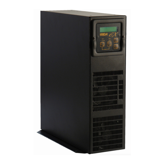
Description This electronic power supply for single phase or double phase 230Vac 50/60hz input, has been designed to feed from 1000W to 3000W short arc Xenon lamps, meeting all the requirements of lamp manufacturers to ensure correct operation, long life to the lamp, and high reliability. -
Page 6: Block Diagram
Block diagram 1. Input filter limiting the high frequency interferences (complying with EmC/EC standards). 2. PFC Converting the alternated voltage from the mains and reducing the emission of harmonic currents (in compliance with En 61000-3-12 standard). 3. Inverter Designed in compliance with mosfet technology, half-bridge configuration 4. -
Page 7: Technical Characteristics
0-10V signal, serial line remote control rs232 serial line - baud rate: 9600, parity: none data bit: 8, communica- tion protocol: IrEm output signals [dry contacts] lamp on, alarms on Input signals 0-10V signal, emergency, on/oFF remote, stand-by mode operating temperature [°C]... -
Page 8: Functions And Controls
Functions and controls Control devices synoptic panel output terminal block Input terminal block rs232 connector Auxiliary connector MAN02774E/1... -
Page 9: Connection And Operating Information
Carefully lift the unit by means of its handles. Avoid any shock when moving. Installation - environment The performance of the EX-100D/1 electronic power supply is guaranteed for a temperature range variable between -5°C and +45°C. Check that the place where the equipment is to be installed is sufficiently ventilated to prevent the air around the unit from exceeding this limit. -
Page 10: Warnings
Non-residential use. Mounting position EX-100D/1 electronic power supply is equipped with two fixing brackets and two han- dles that may be used as an anchoring for the unit (see on picture below). The picture below also shows the synoptic panel displacement for the two mounting featurings. - Page 11 Connection and operating information Feet mounting If feet and handles are used as fixing flanges, holes have to be cut as per following pictures: MAN02774E/1...
-
Page 12: Connecting Input/Output Cables
Connection and operating information The connection must be carried out in compliance with the current safety stan- dards. For a correct operation of the unit, please strictly follow these recom- mendations: - the mains voltage has to be within the two operating limits i.e.: 185-265V, 50/60hz (l,n,pE or 1ph,2ph,pE) withstanding a line current of 22 A. -
Page 13: Protective Plate
Connection and operating information Protective plate Take off the metal protective plates as per following steps: - Be sure the unit is not powered - Loose the fixing screws (A-B) located on the rear panel - Take off the metal plates - perform the electrical connections - Take in place the metallic plates (1-2) - Tighten the screws (A-B). -
Page 14: Auxiliary Connectors
Connection and operating information Auxiliary connectors When using the remote control perform connections through Jp/1 or J/p2 connectors placed on the rear of the unit. Important note: different connections may cause dangerous failures to the unit ! J/P1 connector rs-232 serial port for remote control J/P2 connector (InpuT*) 0-10V analog input for lamp current monitoring (under Ext_10V mode) (InpuT*) on/oFF remote... -
Page 15: Whatʼs New
A password (125 ) protects the operating parameters of the power supply. This pass- word may be customized by the user. If forgotten, please contact IrEm After-sales dept. to “unlock” the unit through a passe-partout password. -
Page 16: Directions For Use
Directions for use Start-up - Be sure the emergency terminals 5-6 on Jp/2 are shorted through a wire if there is no emergency push button. otherwise the power supply cannot operate and the following message will be displayed on the synoptic panel: - If the switching on of the unit has to be performed remotely , insert a switch or two n.o. -
Page 17: Functions And Controls
Functions and controls Synoptic panel The synoptic panel is composed by: 1) Display 2) lEDs 3) Keys for programming/displaying purposes In details: 1) Display two 16-characters lines. It is useful for displaying menus, machine parameters and measurements performed. 2) lEDs, lit to indicate green lED input mains on yellow lED... - Page 18 Functions and controls Synoptic panel When switching on the unit, the synoptic panel will display: 1) DIsplAY mode This mode is highlighted by the coming on of the following lEDs on the synoptic panel: . lInE lED . mAn lED Keys: to decrease the current value (active under manual operation from synoptic panel only)
- Page 19 Functions and controls Synoptic panel The display lower line shows some information contained in the different fields: X X X s Y Y Y Y w a a Z Z Z keys: XXX: operation modes: rem = on/oFF remote (manual lED is on) Vdc = 0-10V mode rs = rs232 mode Remark: under manual mode (i.e.
- Page 20 Functions and controls Synoptic panel 2) under progrAm mode. This operating condition is highlighted by the coming on of the following lEDs on the synoptic panel: . lInE lED . prog lED Important note: enter the password to modify the operating parameters ! The password is: 125 Detailed instructions for entering the password have to be found in the relevant flow- charts.
-
Page 21: Directions For Use
Directions for use When switching on the unit, the first screen displays the manufacturer’s name and the appliance model. Display menu is now available. The available menus are: 1) display menu 2) program menu. Display menu MAN02774E/1... -
Page 22: Changing The Current Set-Point
Directions for use Changing the current set-point (under mAnuAl mode - on/oFF for synoptic panel o from remote command) modify the current set-point by pressing and holding one of the two setting keys for at least 2 seconds. MAN02774E/1... -
Page 23: Directions For Data Entering
(as shown in the flowchart) any number. This will allow to go back to display menu (after the access has been denied). Contact IrEm technical dept. to unblock the unit through a “dedi- cated” password. 2) From any position of the program menu twice press the key EsC to go back to display menu. - Page 24 Directions for use Directions for data entering An example setting the lamp parameters (from 3000W down to 2755W) From lamp parameter display menu press oK to enter the editing mode (the dash starts to flash: enter mode is ON). press the left arrow to decrease the “thou- sands”...
-
Page 25: Entering The Password
Directions for use Entering the password MAN02774E/1... -
Page 26: Parameter Setting
Directions for use Parameter setting lamp p (operating range: 700 - 3400W): max. power of the lamp. When entered, an automatic control will avoid exceeding this value. Factory setting: 3400W. lamp I (operating range: 39- 111A): max. admitted current of the lamp. When entered, an automatic control will avoid exceeding this value. - Page 27 Directions for use Program menu - Parameter setting MAN02774E/1...
- Page 28 Directions for use Program menu - Parameter setting MAN02774E/1...
- Page 29 Directions for use Program menu - Parameter setting MAN02774E/1...
-
Page 30: Operation Modes
Directions for use Operation modes The tree operation modes can be used alternately but not all at the same time. Act on the keys of the synoptic panel to shift from one mode to the other. The default mode is: manual mode from synoptic panel. When the rs232 serial line is on, the operating parameters will be sent through this line. - Page 31 Directions for use Program menu - operating mode setting MAN02774E/1...
-
Page 32: Resetting The Lamp Hor Meter
Directions for use Resetting the lamp hour meter When replacing the lamp it is possible to manually reset its hour meter. Enter the relevant menu (see picture below) and press keys at the same time. MAN02774E/1... -
Page 33: Alarm/Fault Displaying
Alarm/fault displaying Corrective steps When activating the emergency push button, the lamp turns off. To restart the unit, be sure that the dry contact on pins 5 and 6 of J/p2 connector is closed. The power supply has been fitted with some protective devices against overtemperature and overload, bad mains conditions and rectifier incorrect operating conditions. - Page 34 Alarm/fault displaying Corrective steps e 3: if the frequency is out of the admitted limits, this will cause the following: . the display lower line will display: e 3 . the lamp will be turned off . the alarm lED comes and stays on .
- Page 35 Alarm/fault displaying Corrective steps If the requirements for equipotential conditions do not complied with, the following troubles could occur when striking the lamp: 1. The power supply does not strike the lamp, the display is off or some unrecognizable characters are displayed: - turn off the power supply.
-
Page 36: Overall Dimensions
Overall dimensions MAN02774E/1... - Page 37 IREM (by way of example but not by way of limitation, the cases in which: devices or spare parts not supplied by IREM are installed on the machinery;...
- Page 38 Conservare il presente manuale nei pressi dell'apparecchiatura per un'immediata consultazione. IREM SpA a socio unico ha diritti di proprietà intellettuale sulle informazioni e sui dati forniti nel presente manuale. Essi pertanto sono forniti in forma riservata e non dovranno essere trasmessi a terzi e/o usati impropriamente.
- Page 39 Indice DEsCrIZIonE Descrizione ..................... 40 sChEmA A BloCChI schema a blocchi ..................41 CArATTErIsTIChE TECnIChE Caratteristiche tecniche ................42 ConTrollI E FunZIonI Dispositivi di controllo ................43 CollEgAmEnTI E mEssA In sErVIZIo Ricevimento dellʼapparecchiatura ............44 Composizione della fornitura ..............44 Immagazzinamento .................
-
Page 40: Descrizione
Descrizione Questo alimentatore elettronico è stato progettato per alimentare lampade Xenon ad arco corto con potenze da 1000 a 3000W. Il raddrizzatore può essere alimentato con reti monofase o bifase 230Vac 50/60hz. Lʼapparecchio è stato realizzato in piena rispondenza ai requisiti richiesti dai costruttori di lampade e garantisce un corretto funzionamento, lunga vita ed elevata affidabilità... -
Page 41: Schema A Blocchi
Schema a blocchi 1. Scheda filtro input necessaria per contenere le emissioni condotte in alta frequenza, generate dallʼapp- arecchiatura verso la rete (conforme a normative EmC / CE). 2. PFC converte la tensione alternata di rete e riduce le emissioni di correnti armoniche in conformità... -
Page 42: Caratteristiche Tecniche
0-10V, linea seriale Controllo a distanza linea seriale rs232 - baud rate: 9600, parità: nessuna data bit: 8, protocollo comunicazione: IrEm segnali uscita [contatti secchi] lampada accesa, allarmi attivi segnali ingresso segnale 0-10V, emergenza, on/oFF remoto, modalità... -
Page 43: Controlli E Funzioni
Controlli e funzioni Dispositivi di controllo pannello sinottico morsettiera uscita morsettiera ingresso Connettore rs232 Connettore ausiliario MAN02774E/1... -
Page 44: Collegamenti E Messa In Servizio
Al ricevimento della merce verificare lʼintegrità dellʼimballo. In presenza di danneggia- menti segnalarli al responsabile del trasporto. Composizione della fornitura la fornitura è composta da: un raddrizzatore elettronico EX-100D/1 staffe metalliche per il posizionamento verticale staffe metalliche per il posizionamento orizzontale connettore ausiliario... -
Page 45: Avvertenze
Posizionamento EX-100D/1 è dotato di due staffe di fissaggio e di due maniglie che possono venire usate come ancoraggio (vedi disegni sottostanti). Il disegno mostra anche il posizionamento del pannello sinottico per le due configurazioni di posizionamento. - Page 46 Collegamenti e messa in servizio Piedini dʼappoggio Se si utilizzano i piedi e le maniglie come flange di fissaggio, per le forature riferirsi alla dima di fissaggio della figura seguente. posizionamento verticale / rack posizionamento orizzontale MAN02774E/1...
-
Page 47: Collegamento Dei Cavi Ingresso/Uscita
Collegamenti e messa in servizio I collegamenti elettrici devono essere seguiti in conformità alle vigenti norme riguardanti la sicurezza. Il collegamento dellʼapparecchiatura, al fine garantire un corretto funzionamento, deve essere eseguito osservando scrupolosamente quanto di seguito riportato: - lʼalimentazione in ingresso deve essere nei limiti ammessi cioè: 185-265V, 50/60hz (l,n,pE oppure 1ph,2ph,pE) con capacità... -
Page 48: Piastra Di Protezione
Collegamenti e messa in servizio Piastra di protezione rimuovere le piastre come da istruzioni sottostanti: - accertarsi che lʼapparecchiatura non sia sotto tensione - allentare le viti (A-B) del pannello posteriore - rimuovere le piastre - effettuare i collegamenti elettrici - riposizione le piastre (1-2) - fissare le viti (A-B). -
Page 49: Connettori Ausiliari
Collegamenti e messa in servizio Connettori ausiliari Per lʼutilizzo del comando a distanza, occorre procedere ai collegamenti sui connettori JP/1 oppure JP/2 sul retro dellʼapparecchio. Attenzione: connessioni diverse da quelle indicate possono provo- care gravi danni allʼapparecchiatura ! connettore J/P1 porta seriale rs-232 per il comando a distanza connettore J/P2 (InpuT*) 0-10V ingresso analogico per controllo/impostazione della corren-... -
Page 50: Implementazioni
(125 ) personalizzabile dallʼutente protegge i parametri di funzio- namento. se la password viene dimenticata occorre contattare il servizio post-Vendita IrEm che provvederà a sbloccare la macchina con una chiave passe-partout. la potenza massima è uno dei parametri che si può impostare. Durante il funzionamen- to il raddrizzatore controlla che la potenza erogata non superi il valore preimpostato. -
Page 51: Utilizzo Dellʼapparecchiatura
Utilizzo dellʼapparecchiatura Verifiche - in mancanza dellʼinterruttore di emergenza, occorrerà cortocircuitare con un cavetto i morsetti di emergenza 5 e 6 di JP/2. altrimenti lʼalimentatore non funziona e appare il seguente messaggio: - se lʼaccensione della macchina avviene in remoto, occorrerà inserire un interruttore oppure due contatti secchi n.A. -
Page 52: Controlli E Funzioni
Controlli e funzioni Pannello sinottico Il pannello sinottico è formato da: 1) Display 2) lED 3) tasti per la programmazione e la visualizzazione In particolare: 1) Display Due righe di 16 caratteri ciascuna. Consente la visualizzazione dei vari menu, dei parametri macchina e delle misure effettuate. - Page 53 Controlli e funzioni Pannello sinottico Allʼaccensione della macchina, il pannello sinottico visualizzerà: 1) modalità DIsplAY I lED sottostanti si illuminano quando questa modalità è attiva . lInE lED . mAn lED I tasti hanno le seguenti funzioni: decrementa il valore della corrente (attivo unicamente in manuale da sinottico).
- Page 54 Controlli e funzioni Pannello sinottico la riga inferiore del display riporta alcune informazioni presenti nei vari campi: s Y Y Y Y w a a Z Z Z X X X chiave di lettura: XXX: modalità di funzionamento: rem = on/oFF remoto (il lED manual è acceso) Vdc = modalità...
- Page 55 Controlli e funzioni Pannello sinottico 2) In modalità prog Lo stato è evidenziato dallʼaccensione dei seguenti LED: . lInE lED . prog lED Importante: per poter variare i parametri occorre prima inserire la password! la chiave di accesso è: 125 Istruzioni particolareggiate per lʼinserimento della password sono riportate più...
-
Page 56: Utilizzo Dellʼapparecchiatura
Utilizzo dellʼapparecchiatura Allʼaccensione, la prima schermata disponibile visualizzerà il nome del costruttore ed il modello della macchina. Il menu display è attivo. I menu sono: 1) menu display 2) menu program. Menu display MAN02774E/1... -
Page 57: Modifica Del Set-Point Di Corrente
Utilizzo dellʼapparecchiatura Modifica del set-point di corrente (in modalità mAnuAl - on/oFF da sinottico o da remoto) per cambiare il set-point di corrente occorre tener premuto per almeno 2 secondi uno dei due tasti per il settaggio. MAN02774E/1... -
Page 58: Inserimento Dati
(vedi flowchart). Questo permetterà di ritornare al menu display (dopo che lʼaccesso è stato negato). Contattare il Servizio Tecnico IREM per sbloccare con chiave dedicata. 2) Da qualsiasi punto del menu prog premere due volte EsC per ritornare al menu display. - Page 59 Utilizzo dellʼapparecchiatura Inserimento dati Esempio decremento valori lampada da 3000W a 2755W) Dal menu “lamp parameters” premere oK per accedere al menu inserimento dati (il trattino inizia a lampeggiare: la modalità di inserimento è attiva). premere la freccia “a sinistra” per decre- mentare il campo “migliaia”...
-
Page 60: Inserimento Password
Utilizzo dellʼapparecchiatura Inserimento password MAN02774E/1... -
Page 61: Impostazione Parametri
Utilizzo dellʼapparecchiatura Impostazione parametri lamp p : (range funzionamento: 700-3400W) massima potenza lampada. una volta inserito questo valore, un controllo automatico ne impedirà il superamento. Valore preimpostato: 3400W. lamp I (range: 39 - 111A): massima corrente lampada. una volta inserito questo valore, un controllo automatico ne impedirà... - Page 62 Utilizzo dellʼapparecchiatura Menu Program - Impostazione parametri MAN02774E/1...
- Page 63 Utilizzo dellʼapparecchiatura Menu program - Impostazione parametri MAN02774E/1...
- Page 64 Utilizzo dellʼapparecchiatura Menu Program - Impostazione parametri MAN02774E/1...
-
Page 65: Modalità Di Funzionamento
Utilizzo dellʼapparecchiatura Modalità di funzionamento le tre modalità di funzionamento possono essere usate alternativamente ma non contemporaneamente. la modalità di default è manuale da sinottico. Quando la linea seriale rs232 è attiva, i parametri di funzionamento saranno inviati tramite questʼultima. In qualsiasi modalità, premere questi tasti per cambiare la modalità. - Page 66 Utilizzo dellʼapparecchiatura Menu Program - Impostazione modalità di funzionamento MAN02774E/1...
-
Page 67: Ripristino Del Contaore Lampada
Utilizzo dellʼapparecchiatura Ripristino del contaore lampada Eʼ possibile procedere al ripristino manuale del contaore al momento della sostituzione della lampada. Accedere al menu corrispondente (vedi figura sottostante) e premere contemporane- amente i tasti MAN02774E/1... -
Page 68: Allarmi/Visualizzazione Anomalie
Allarmi / visualizzazione anomalie Interventi correttivi La lampada si spegne quando si attiva lʼinterruttore di emergenza. Per il ripristino, occorre accertarsi che il contatto secco sui pin 5 e 6 di J/p2 sia chiuso. la macchina è provvista di protezioni contro la sovratemperatura, il sovraccarico, condizioni di rete non ottimali e malfunzionamento. - Page 69 Allarmi / visualizzazione anomalie Interventi correttivi e 3: se la frequenza è al di fuori del range ammesso: . la riga inferiore del display visualizzerà: e 3 . la lampada si spegne . il lED allarmi si illumina . ripristinare premendo il tasto EsC (il display si azzera ed il lED allarmi si spegne) .
- Page 70 Allarmi / visualizzazione anomalie Interventi correttivi Se i requisiti di equipotenzialità non vengono rispettati, allʼaccensione della lampada si potrebbero verificare le seguenti problematiche: 1. lʼalimentatore non accende la lampada, il display è spento oppure visualizza dei caratteri non riconoscibili: - spegnere lʼalimentatore. - interrompere la comunicazione rs232 dal dispositivo remoto - accendere nuovamente lʼalimentatore, attendere la comparsa della scritta “current setting”...
-
Page 71: Dimensioni
Dimensioni MAN02774E/1... - Page 72 INFORMATION ABOUT DISPOSAL OF THE APPLIANCE Do not treat the appliance as unsorted municipal waste. The disposed appliance must be consigned to the authorized treatment facilities for proper recycling/reuse and disposal. An incorrect disposal may cause harmful effects on environment and human health. INFORMAZIONI PER LO SMALTIMENTO Non smaltire l’apparecchiatura come rifiuto urbano misto.
- Page 73 IREM (quali, a mero titolo esemplificativo e non esaustivo, ipotesi in cui: sui reparti e/o singoli macchinari vengano installati apparecchiature o ricambi non forniti da IREM;...
Need help?
Do you have a question about the EX-100D/1 and is the answer not in the manual?
Questions and answers