Advertisement
Quick Links
Advertisement

Summary of Contents for Solartron Metrology BICM Series
- Page 1 BICM (Boxed Inline Conditioning Module) user leaflet...
- Page 2 Index Section Title Page Index ......1 Introduction ....2 Technical Specification .
- Page 3 1.0: Introduction 1.0: Introduction & Glossary The Boxed Inline Conditioning Module (BICM) is an electronics module that may be used with a wide range of LVDT transducers. Layout and size are designed to allow the BICM to be easily fitted inline with the transducer cable and installed with the minimum of effort (or changed if ready connected to a transducer) The BICM output may be set for a full scale range up to ±10 VDC, offset facilities are provided.
-
Page 4: Technical Specification
2.0: Technical Specification Standard BICM IP67 BICM Bipolar Supply Unipolar Supply Bipolar Supply Power Requirement Voltage ±15 V ±1.5 V 24 V ±2.4 V ±15 V ±1.5 V Current ±15 mA nominal 30 mA nominal ±15 mA nominal Transducer Excitation Primary Voltage 2 Vrms nominal Primary Frequency 1... - Page 5 2.0: Technical Specification Standard BICM IP67 BICM Bipolar Supply Unipolar Supply Bipolar Supply Signal Output Voltage Output Up to ±10 V Current Output 11 mA Output Ripple <14 mVrms Output Offset 100% <0.03% FRO / o C Temp Co. Gain <0.025% FRO / o C Temp.
- Page 6 2.0: Technical Specification Standard BICM IP67 BICM Bipolar Supply Unipolar Supply Bipolar Supply Environmental 0 - 70 o C Operation Temperature Range -20 to +85 o C Storage Temperature Range IP Rating IP40 IP67 Mechanical and Connections Connections Solder pad or factory fit Factory fit only Enclosure Size 98.5 x 30.5 x 13.0 mm...
- Page 7 3.0: Operational and Set-Up Guide - BICM Kit 3.1: Introduction The BICM kit is supplied with a selection of potentiometers and an output cable allowing users to connect LVDT sensors and set up to their own requirements. Connections are made to the BICM PCB as shown in Fig. 3.1A or Fig. 3.1B below depending on the PCB version. The BICM output is adjustable for GAIN and OFFSET.
- Page 8 3.0: Operational and Set-Up Guide - BICM Kit Secondary 2 Green Vout Yellow Secondary 1 White 0V (Signal white Screen +15 V Bipolar +24 V Unipolar 0V Supply Green Primary Exc1 Blue -15V Bipolar only Blue Primary Exc 2 Red Fig.
- Page 9 3.0: Operational and Set-Up Guide - BICM Kit 3.2: Screen Connection The screen connection is arranged so that the transducer cable screen and I/O cable screen is connected and that some cable strain relief is provided whilst setting up the board. Screens are not connected to 0V on the PCB. Screen and 0V may be connected on the PCB by using a wire link or at the user connection end, for example at the PSU, but it all depends on the installation requirements.
- Page 10 3.0: Operational and Set-Up Guide - BICM Kit TRANSDUCER POTENTIOMETER VALUE (ohms) GAIN OFFSET B2.5 100K B5.0 100K 100K 100K B100 Top View Transducer Connection Side View Fit this way round FIG 5.1 COMPONENT INSTALLATION Fig. 3.3 Component Installation 3.0: Operational Guide 501651 Issue 13...
- Page 11 3.0: Operational and Set-Up Guide - BICM Kit 3.3. Gain Adjustment Gain adjustment is best done before offset adjustment. If an OFFSET potentiometer has been fitted then set this to the mid position. GAIN SETUP PROCEDURE 1) Adjust the potentiometer to the approximate mid position, about 12 full turns from either end. 2) Adjust the LVDT core position to give 0V output.
- Page 12 3.0: Operational and Set-Up Guide - BICM Kit 3.5. Set Up Using Fixed Value Resistors Fit the components into the positions shown in Fig 3.4 once component values have been determined using the set up procedure. The term nearest preferred value (NPV) is used throughout. This is a resistor selected from standard ranges (E24,E48 etc) that most closely matches the value required.
- Page 13 3.0: Operational and Set-Up Guide - BICM Kit TRANSDUCER APPROXIMATE RESISTOR VALUE (ohms) GAIN OFFSET (+ or -5V) B1.5 B2.5 B5.0 B100 Fig 3.4 Resistor Positions 3.0: Operational Guide 501651 Issue 13...
- Page 14 3.0: Operational and Set-Up Guide - BICM Kit 3.6. Gain Set Up Procedure If this procedure is to be used to determine the value of potentiometer required perform up to step (6). The potentiometer value will be the NPV greater than the resistor value determined. 1) Temporarily connect a variable resistance (such as a decade box) to the board as in Fig.
- Page 15 3.0: Operational and Set-Up Guide - BICM Kit 6) Fit a NPV fixed resistor that is just below the value required to position R1. Reconnect the temporary variable resistor to position R2, see Fig 3.6(b). 7) Repeat steps 2 & 3, moving the core between the null position and the full scale position adjusting the variable resistor as necessary to achieve the required output.
- Page 16 3.0: Operational and Set-Up Guide - BICM Kit 3) Adjust the variable resistance until the required offset is achieved. 4) If a single resistor is to be fitted, fit a NPV fixed resistor to position +R4 or -R4 . Fit a wire link to position R3. If two resistors are to be used for a more accurate calibration see step (5).
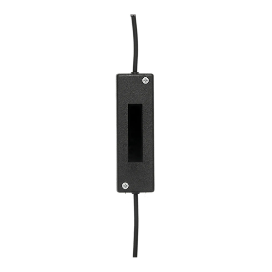
- Page 17 4.0: The Case The BICM case comprises two identical halves which are simply clamped around the PCB and connecting cables. Four self tapping screws are used to secure the halves together. Please note each half has a step along the side. The case halves will only mate correctly one way round. DO NOT OVER TIGHTEN THE SCREWS when reassembling the case.
- Page 18 5.0: The "Why Doesn't it Work Guide" This is not an exhaustive list of problems but may help cure some of more common problems. FAULT CONDITION POSSIBLE CAUSE OF FAULT NO OUTPUT Power supply Is it connected correctly? Is it turned on? Is there at least ±13.5 VDC at the power supply pads of the bipolar or +21.6 V for unipolar BICM? Transducer Is it connected correctly?
-
Page 19: Application Notes
6.0: Application Notes 6.1. Transducer The MACH 1 5 kHz Series range of Transducer coil assemblies are designed for protection against dust and water to IP66, making them suitable for use in harsh environments. Designed to be rugged and yet still cost effective, these devices offer the Customer all the attributes associated with LVDT’s. A variety of combinations and accessories are available as options. - Page 20 6.0: Application Notes 6.1.2. Installation (continued) Irrespective of clamping method care must be taken not to overtighten retaining screws as distortion of the body may prove damaging to the integrity of the transducer and adversely affect the geometry of the installation. If the LVDT is to be mounted on equipment subject to high ”g”...
- Page 21 6.1.8. Cable Solartron Metrology cable is specially manufactured to optimise performance with respect to temperature, chemical resistance, flex life, abrasion resistance and electrical performance. However, no single cable design can fulfil every known requirement and by taking a few simple precautions cable failure can be avoided.
- Page 22 6.0: Application Notes IF POSSIBLE CENTRALISE L.V.D.T. NON-METALLIC SPLIT (TUFNOL) BUSH FOR USE WITH METALLIC CLAMP Fig 6.1 Examples of Clamping Methods 6.0: Application Notes 501651 Issue 13...
- Page 23 6.0: Application Notes 6.2. Example 1 B15 TRANSDUCER ±15 mm stroke (30 mm total stroke) BICM output ±10 V output, no offset 1) Fit the 100 k potentiometer to the GAIN position on the BICM board. 2) No offset is required so the 50 k potentiometer is NOT fitted to the GAIN position on the BICM board. 3) Connect the transducer to the BICM according to Fig.
- Page 24 6.0: Application Notes 6.2. Example 1 (continued) 7) Move the core 15 mm inwards from the null position. The voltmeter should indicate a Positive increase in output. 8) Adjust the GAIN potentiometer clockwise until +10 V is indicated on the voltmeter. 9) Move the core back to the null position then repeat steps (6) to (8) until satisfied with the calibration.
- Page 25 6.0: Application Notes 6.3. Example 2 (continued) 11) For a 0 to 5 V output simply adjust the OFFSET potentiometer until the -2.5 V reading on the voltmeter shows 0V. If the core is moved to the mechanical null position +2.5 V should be indicated and +5 V at the fully out position. 6.4.
Need help?
Do you have a question about the BICM Series and is the answer not in the manual?
Questions and answers