Table of Contents
Advertisement
Available languages
Available languages
Quick Links
1 ZONE WALL MOUNTING RADIO RECEIVER
RECEPTEUR RADIO 1 ZONE POUR MONTAGE EN SAILLIE
FUNKEMPFÄNGER 1 ZONE WANDMONTAGE
RICEVITORE RADIO 1 ZONA DA PARETE
RECEPTOR RADIO DE 1 ZONA DE PARED
lm - DERXPE001
02/18
Model with burner or solenoid valve control in wireless
temperature control systems
Modèle avec commande pour chaudière ou électro-
vanne en systèmes de réglage thermique sans fils
Modell mit drahtloser Steuerung für Durchlauferhitzer
oder Elektroventil in Heizanlagen
Modello con comando per caldaia o elettrovalvola in
impianti con sistema di termoregolazione senza fili
Modelo para controlar calderas o electroválvulas en
instalaciones de termorregulación sin cables
Advertisement
Table of Contents

Related Manuals for Perry Electric 1TX RX01/P

Summary of Contents for Perry Electric 1TX RX01/P
- Page 1 1 ZONE WALL MOUNTING RADIO RECEIVER RECEPTEUR RADIO 1 ZONE POUR MONTAGE EN SAILLIE FUNKEMPFÄNGER 1 ZONE WANDMONTAGE RICEVITORE RADIO 1 ZONA DA PARETE RECEPTOR RADIO DE 1 ZONA DE PARED Model with burner or solenoid valve control in wireless temperature control systems Modèle avec commande pour chaudière ou électro- vanne en systèmes de réglage thermique sans fils...
- Page 2 TECHNICAL SPECIFICATIONS - INSTRUCTIONS FOR EN - English Page 3 THE INSTALLER - PUTTING INTO OPERATION AND USE DONNÉES TECHNIQUES - INSTRUCTIONS POUR Page 13 FR - Français L’INSTALLATEUR - MISE EN MARCHE ET UTILISATION TECHNISCHE DATEN - NORMEN FÜR DIE INSTALLATION DE - Deutsch Seite 23 - INBETRIEBNAHME UND GEBRAUCH...
-
Page 3: Technical Specifications
ENGLISH TECHNICAL SPECIFICATIONS Supply voltage: 230 V~ 50-60 Hz Device Absorption: 2,5 VA max Type of action, disconnection and appliance: 1/B/Electronic Type of Output: 1 relay with unipolar changeover contact NC/NO/COM, voltage-free 5(2) A / 250 V~ Wire section at terminals: min. -
Page 4: Instructions For The Installer
1 - INSTRUCTIONS FOR THE INSTALLER 1.1 - INSTRUCTIONS AND REQUIREMENTS FOR INSTALLING THE RECEIVER Install the receiver at a height that allows the antenna to stick up above any nearby metal container (boiler, expansion tanks, metal cabinets); avoid positioning the antenna near cables and electrical panels (fig. 1.i - fig. 2.i) Cabinets, walls and slabs containing metal can limit the operation of the product This system is incompatible with radio products a working on the same frequency using permanent emission mode. - Page 5 1.2 - INSTALLING THE BASE ON THE WALL Installing the device: INDEPENDENT - FIXED ATTENTION: INSTALLATION MUST BE PERFORMED AFTER SECTIONING THE MAINS SUPPLY - 230 V~. RESET For installation, it is necessary to separate the front part, complete with electronic card, from the base.
-
Page 6: Electrical Connections
1.3 - ELECTRICAL CONNECTIONS 230 V~ Burner SWITCH MAINS SUPPLY 230 V~ OFF With reference to figures 6.i, 7.i and 8.i: Make the connection to the mains supply Example of a burner terminal = NEUTRAL connection terminal = LINE L1 L2 Fig. - Page 7 1.4 - ATTACHING THE FRONT WITH CARD TO THE BASE Reinsert the front part with card on the base being careful to correctly insert the pins connecting the card to the terminals. Push the front on to the base using both hands as shown in figure 9.i, until the catches click and lock the front to the base.
-
Page 8: Putting Into Operation And Use
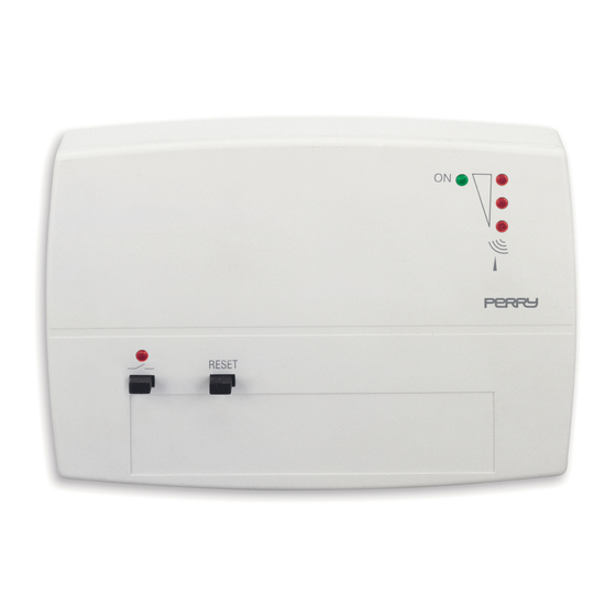
2 - PUTTING INTO OPERATION AND USE 2.1 - SIGNAL AND COMMAND LEGEND LED ON: Appearance of the lighted signals lit = power present intermittent = transmitter malfunction Fixed off Intermittent (t on = t off) VMETER: every second LED “ “... - Page 9 2.2 - NEW DEVICE When turned on, the receiver has only the ON LED lit. N.B.: There may be a weak lighted signal on the lower of the VMETER , due to the presence of radio interference. 2.3 - TEMPORARILY FORCING THE STATE OF THE CONTROL OUTPUT (for example, to test the system) A) TRANSMITTER NOT YET COUPLED OR NOT ACTIVE Hold down the “...
- Page 10 2.4 - COUPLING TO A TRANSMITTER Activate the “Test” state on the transmitter to be coupled, as explained in the chapter “ Coupling to the receiver ” in the transmitter manual. A) - FIRST COUPLING TO A TRANSMITTER Fig. 6 ON THE RECEIVER “...
-
Page 11: Normal Operation
2.5 - CHECKING THE INTENSITY OF THE RECEIVED SIGNAL - VMETER ON THE TRANSMITTER Activate the “check the intensity of the radio signal mode”, as explained in the specific chapter of the transmitter manual. ON THE RECEIVER SIGNAL INTENSITY The intermittent “ ”... - Page 12 2.7 - SIGNALING A TRANSMITTER MALFUNCTION The receiver reports two types of transmitter anomalies: Failure to receive a radio signal for more than 30 minutes Transmitter battery almost dead In both cases, the signal is given by the intermittent, simultaneous lighting of the channel LEDs ATTENTION: in the case of the lack of a radio signal, the control of the load is also...
-
Page 13: Données Techniques
FRANÇAIS DONNÉES TECHNIQUES Tension d'alimentation: 230 V~50 ÷ 60 Hz Absorption du dispositif: 2,5 VA maxi Type d'action, déconnexion et appareil: 1 / B / Electronique Type de sortie: 1 relais avec contact unipolaire en échange, sans potentiel NF/NO/COM - 5(2) A / 250 V~ Section des fils aux bornes: mini. -
Page 14: Instructions Pour L'installateur
1 - INSTRUCTIONS POUR L’INSTALLATEUR 1.1- INDICATIONS ET PRESCRIPTIONS POUR L'INSTALLATION DU RÉCEPTEUR Installer le récepteur à une hauteur qui permet à l'antenne de dépasser la chaudière et les conteneurs métalliques avoisinants (chauffe-eau, vases d'expansions, armoires métalliques); éviter la présence de câbles et de tableaux électriques à proximité de l'antenne (fig. - Page 15 1.2 - INSTALLATION DE LA BASE AU MUR Installation du dispositif: IND PENDANT - FIXE É ATTENTION: L'INSTALLATION DOIT ÊTRE EXÉCUTÉE APRÈS AVOIR COUPÉ L'ALIMENTATION DE 230 V~. RESET Pour l'installation il est nécessaire de séparer la partie avant, qui contient la carte électronique, de la base.
-
Page 16: Branchements Électriques
1.3 - BRANCHEMENTS ÉLECTRIQUES 230 V~ Chaudière DÉSACTIVER L'ALIMENTATION DE RÉSEAU 230 V~. Avec référence aux figures 6.i, 7.i e 8.i : Effectuer la connexion à l'alimentation réseau Exemple de raccordement borne n° = NEUTRE à la chaudière. borne n° = LIGNE L1 L2 Exécuter les branchements électriques au dispositif à... - Page 17 1.4 - FIXATION DE LA PARTIE AVANT ÉQUIPÉE DE CARTE À LA BASE Réinsérer dans la base la partie avant avec la carte en faisant attention à la bonne introduction des broches de connexion de la carte aux bornes. Pousser avec les deux mains la partie avant sur la base, comme illustré...
-
Page 18: Mise En Marche Et Utilisation
2 - MISE EN MARCHE ET UTILISATION 2.1 - LÉGENDE DES INDICATIONS ET COMMANDES LED ON: Aspect des indications lumineuses allumée = alimentation présente intermittente = panne du transmetteur Eteinte fixe Intermittente (t on = t off) VMETER: toutes les secondes LED indicateurs d’intensité... - Page 19 2.2 - APPAREIL NEUF À l'allumage du récepteur, seule la LED ON est allumée. N.B.: de faibles signaux lumineux sont possibles sur la inférieure VMETER , en raison des interférences radio. 2.3 - FORÇAGE TEMPORAIRE DE L'ÉTAT DE LA SORTIE DE COMMANDE (ex.: pour le test du système) A) TRANSMETTEUR PAS ENCORE ASSOCIÉ...
- Page 20 2.4 - ACCOUPLEMENT À UN TRANSMETTEUR Activer, sur le transmetteur à accoupler l'état de “Test”, comme indiqué au chapitre “ Accouplement au récepteur ” du manuel du transmetteur. A) - PREMIER ACCOUPLEMENT À UN TRANSMETTEUR Fig. 6 SUR LE RÉCEPTEUR “...
-
Page 21: Fonctionnement Normal
2.5 - VÉRIFICATION DE L'INTENSITÉ DU SIGNAL RADIO REÇU - VMETER SUR LE TRANSMETTEUR Activer l'état de “vérification de l'intensité du signal radio” , comme indiqué au chapitre spécifique du manuel du transmetteur. INTENSITÉ DU SIGNAL SUR LE RÉCEPTEUR BASSE MOYENNE HAUTE “... - Page 22 2.7 - SIGNAL DE PANNE DU TRANSMETTEUR Le récepteur signale les deux types d'anomalie du transmetteur ci-après: absence de réception du signal radio pendant un délai supérieur à 30 minutes Batterie du transmetteur presque épuisée. Dans les deux cas, la signalisation est due à l'allumage intermittent et simultané de la LED ON et de la du canal.
-
Page 23: Technische Daten
DEUTSCH TECHNISCHE DATEN Versorgungsspannung: 230 V~ 50 ÷ 60 Hz Stromaufnahme des Geräts: 2,5 VA max Antrieb, Trennen der Verbindung und Gerät: 1/ B / Elektronisches Gerät Ausgang: Relais mit unipolarem Weichenkontakt NC / NO / COM und potentialfrei 5(2)A / 250 V~ Kabelquerschnitt für Klemmen: min. - Page 24 1 - NORMEN FÜR DIE INSTALLATION 1.1 - ANLEITUNGEN UND VORSCHRIFTEN FÜR DIE INSTALLATION DES EMPFÄNGERS Installieren Sie den Empfänger so hoch, dass die Antenne höher als der Durchlauferhitzer und andere eventuell vorhandene Metallgegenstände in der Nähe (Boiler, Ausdehnungsgefäße, Metallschränke) angebracht ist; vermeiden Sie Kabel und Schaltkästen in der Nähe der Antenne (Abb.
- Page 25 1.2 - INSTALLATION DER BASIS AN DER WAND Installation der Vorrichtung: UNABHÄNGIG - FEST ACHTUNG: VOR DER INSTALLATION MUSS DIE NETZSPANNUNG VON 230 V~ UNTERBROCHEN WERDEN. RESET Für die Installation muss das Frontteil mit der Steckkarte von der Basis getrennt werden. Abb.
-
Page 26: Elektrische Anschlüsse
1.3 - ELEKTRISCHE ANSCHLÜSSE 230 V~ Durchlauferhitzer TRENNEN SIE DAS STROMNETZ VON 230 V~ AB Unter Bezugnahme auf die Abbildungen 6.i, 7.i und 8.i: Führen Sie den Anschluss an das Stromnetz wie folgt aus Beispiel für den Anschluss an Klemme Nr. = NEUTRALLEITER einen Durchlauferhitzer Klemme Nr. - Page 27 1.4 - SETZEN SIE DAS FRONTTEIL MIT DER STECKKARTE WIEDER AUF DIE BASIS. Achten Sie dabei auf das korrekte Einfügen der Verbindungsstifte zwischen der Steckkarte und den Klemmen. Drücken Sie mit beiden Händen das Frontteil auf die Basis, wie in Abbildung 9.i dargestellt, bis die Blockierungshaken der Basis inrasten.
-
Page 28: Inbetriebnahme Und Gebrauch
2 - INBETRIEBNAHME UND GEBRAUCH 2.1 - LEGENDE MELDUNGEN UND STEUERBEFEHLE LED ON: ANSICHT DER LICHTSIGNALE leuchtet = Speisung Vorhanden blinkend = Fehler im Sender leuchtet überhaupt nicht Blinkt (t ein = t aus) VMETER: jede Sekunden LED Anzeigen der Intensität LED “... - Page 29 2.2 - NEUES GERÄT Beim Einschalten leuchtet am Empfänger nur die LED ON Hinweis: es können auch schwache Lichtsignale auf dem untersten LED des VMETER angezeigt werden. Dies hängt von vorhandenen Funkstörquellen ab. 2.3 - ZEITLICH BEGRENZTE MANUELLE AUSLÖSUNG DES STATUS STEUERUNG VERLASSEN (z.B.
- Page 30 2.4 - ANGLEICHUNG AN EINEN SENDER Aktivieren Sie auf dem anzugleichenden Sender den Status “Test”, wie im Kapitel “Angleichen an den Empfänger ” Bedienungsanleitung des Senders beschrieben. A) - ERSTES ANGLEICHEN AN EINEN SENDER Abb. 6 AM EMPFÄNGER LED “ ”...
- Page 31 2.5 - ÜBERPRÜFEN DER INTENSITÄT DES EMPFANGENEN FUNKSIGNALS - VMETER AM SENDER Aktivieren Sie den Status “Überprüfen der Intensität des funksignals ”, wie im spezifischen Kapitel der Bedienungsanleitung des Senders beschrieben. INTENSITÄT DES SIGNALS AM EMPFÄNGER SCHWACH MITTEL STARK blinkende “...
- Page 32 2.7 - FEHLERMELDUNG DURCH DEN SENDER Der Empfänger meldet die folgenden zwei Arten von Fehlern am Sender: Ausbleiben von Funksignalen seit mehr als 30 Minuten Batterie des Senders fast leer. In beiden Fällen erfolgt die Meldung durch gleichzeitiges Blinken der LED ON und der LED für den Kanal.
-
Page 33: Dati Tecnici
ITALIANO DATI TECNICI Alimentazione: 230 V~ 50÷60 Hz Assorbimento del dispositivo: 2,5 VA max Tipo di azione, disconnessione e apparecchio: 1 / B / Elettronico Tipo di uscita: n° 1 relè con contatto unipolare in scambio, libero da potenziale NC/NA/COM - 5(2) A / 250 V~ Sezione dei fili ai morsetti: min. -
Page 34: Istruzioni Per L'installatore
1 - ISTRUZIONI PER L’INSTALLATORE 1.1 - INDICAZIONI E PRESCRIZIONI PER L’INSTALLAZIONE DEL RICEVITORE Installare il ricevitore ad una altezza che consenta all’antenna integrata di sovrastare la caldaia ed eventuali contenitori metallici vicini (boiler, vasi espansione, armadi metallici); evitare la presenza di cavi e quadri elettrici in prossimità dell’antenna (fig. 1.i - fig. 2.i Armadi, pareti e solette in materiale metallico possono limitare il funzionamento del prodotto. - Page 35 1.2 - INSTALLAZIONE DELLA BASE ALLA PARETE Installazione del dispositivo: INDIPENDENTE - FISSO ATTENZIONE: L’INSTALLAZIONE DEVE ESSERE ESEGUITA DOPO AVER SEZIONATO LA TENSIONE DI RETE 230 V~. RESET Per l’installazione è necessario separare la parte frontale, completa di scheda elettronica, dalla base. Fig.
-
Page 36: Collegamenti Elettrici
1.3 - COLLEGAMENTI ELETTRICI 230 V~ Caldaia DISATTIVARE L’ALIMENTAZIONE DI RETE 230 V~ Con riferimento alle figure 6.i, 7.i e 8.i: Eseguire il collegamento all’alimentazione di rete Esempio di collegamento morsetto n° = NEUTRO alla caldaia morsetto n° = LINEA L1 L2 Eseguire i collegamenti elettrici al dispositivo da comandare Fig. - Page 37 1.4 - FISSAGGIO DEL FRONTALE CON SCHEDA ALLA BASE Reinserire sulla base la parte frontale con scheda facendo attenzione al corretto inserimento dei pin di collegamento della scheda ai morsetti. Spingere con entrambe le mani il frontale sulla base, come indicato in figura 9.i , sino allo scatto di bloccaggio degli appositi denti della base.
- Page 38 2 - MESSA IN FUNZIONE E IMPIEGO 2.1 - LEGENDA SEGNALAZIONI E COMANDI LED ON: Aspetto delle segnalazioni luminose acceso = alimentazione presente intermittente = avaria del trasmettitore Spento fisso Intermittente (t on = t off) VMETER: ogni secondo LED indicatori dell’intensità LED “...
- Page 39 2.2 - APPARECCHIO NUOVO Alla accensione il ricevitore presenta il solo LED ON acceso. N.B.: è possibile la comparsa di deboli segnali luminosi, sul inferiore VMETER , dovuti alla presenza di disturbi radio. 2.3 - FORZATURA TEMPORANEA DELLO STATO DI USCITA DEL COMANDO (es.: per test dell’ impianto) A) TRASMETTITORE NON ANCORA ABBINATO O NON ATTIVO Mantenere premuto il tasto...
- Page 40 2.4 - ABBINAMENTO AD UN TRASMETTITORE Sul trasmettitore da abbinare attivare lo stato di “Test”, come indicato nel capitolo “Abbinamento al ricevitore” del manuale del trasmettitore. A) - PRIMO ABBINAMENTO AD UN TRASMETTITORE Fig. 6 SUL RICEVITORE LED “ ” è spento (ricevitore non abbinato) Mantenere premuto il tasto “...
-
Page 41: Normale Funzionamento
2.5 - VERIFICA DELLA INTENSITÀ DEL SEGNALE RADIO RICEVUTO - VMETER SUL TRASMETTITORE Attivare lo stato di “verifica della intensità del segnale radio” ,come indicato nello specifico capitolo del manuale del trasmettitore. INTENSITÀ DEL SEGNALE SUL RICEVITORE ALTA MEDIA BASSA “... - Page 42 2.7 - SEGNALAZIONE DI AVARIA DEL TRASMETTITORE Il ricevitore segnala i due seguenti tipi di anomalia del trasmettitore: assenza di ricezione del segnale radio per un tempo superiore a 30 minuti batteria del trasmettitore quasi scarica. In entrambi i casi la segnalazione è data dall’accensione intermittente e contemporanea LED ON e del LED del canale.
-
Page 43: Datos Técnicos
ESPAÑOL 1 - DATOS TÉCNICOS Tensión de alimentación: 230 V~ 50 ÷ 60 Hz Consumo: 2,5 VA máx Tipo de acción, d sconexión y aparato: 1/ B / Electrónico Tipo de salida: 1 relé con contacto en intercambio, unipolar NC / NA / COM libre de potencial - 5(2)A / 250 V~ Sección de los cables a los bornes: min. -
Page 44: Instrucciones Para El Instalador
1 - INSTRUCCIONES PARA EL INSTALADOR 1.1 - INSTRUCCIONES DE INSTALACIÓN DEL RECEPTOR Instalar el receptor de modo que la antena quede más alta que la caldera y que los contenedores metálicos cercanos (calentador, tanques de expansión y armarios metálicos). Cerca de la antena no debe haber cables ni cuadros eléctricos (fig. 1.i - fig. 2.i). Las paredes, las plataformas y los armarios metálicos pueden afectar el funcionamiento del dispositivo. -
Page 45: Instalación De La Base En La Pared
1.2 - INSTALACIÓN DE LA BASE EN LA PARED Instalación del dispositivo: INDEPENDIENTE - FIJO ATENCIÓN: LA INSTALACIÓN DEBE REALIZARSE LUEGO DE HABER RESET CORDATO LA LINEA DE ALIMENTACIÓN 230 V~. Fig. 3.i Separar la base de la parte frontal con tarjeta electrónica. Introducir un destornillador en las ranuras laterales y girarlo hacia adelante para ejercer una ligera presión sobre el gancho (fig. -
Page 46: Conexiones Eléctricas
1.3 - CONEXIONES ELÉCTRICAS 230 V~ Caldera DESACTIVAR LA TENSIÓN DE LA RED 230 V~ Figuras 6.i, 7.i y 8.i: Efectuar conexión a la red Ejemplo de conexión borne n° = NEUTRO a una caldera borne n° = LÍNEA L1 L2 Efectuar las conexiones eléctricas al equipo que se desea controlar Fig. - Page 47 1.4 - CÓMO FIJAR EN LA BASE LA PARTE FRONTAL CON TARJETA Unir a la base la parte frontal con tarjeta introduciendo correctamente las clavijas de conexión de la tarjeta en los bornes. Empujarla con ambas manos como se indica en la figura 9.i hasta que los ganchos de la base queden encastrados.
-
Page 48: Puesta En Funcionamiento Y Uso
2 - PUESTA EN FUNCIONAMIENTO Y USO 2.1 - REFERENCIAS DE LAS SEÑALES Y MANDOS LED ON: Espera de señales luminosas encendido = alimentación conectada intermitente = avería del transmisor Apagado fijo Intermitente (t on = t off) VMETER: cada segundo LED de intensidad de la LED “... - Page 49 2.2 - APARATO NUEVO Cuando se enciende el receptor, el único que se enciende es NOTA: es posible que aparezcan señales luminosas débiles en el LED inferior VMETER , por la presencia de interferencias de radio. 2.3 - FORZAMIENTO TEMPORAL DEL ESTADO DE LA SALIDA DEL MANDO (ej.: para probar la instalación) A) TRANSMISOR NO COMBINADO O NO ACTIVO Mantener presionada la tecla...
- Page 50 2.4 - COMBINACIÓN CON UN TRANSMISOR En el transmisor que se desea combinar hay que activar el estado “Test”, como se indica en el capítulo “Combinación con el receptor” del manual del transmisor. A) - PRIMERA COMBINACIÓN CON UN TRANSMISOR Fig.
-
Page 51: Funcionamiento Normal
2.5 - VERIFICACIÓN DE LA INTENSIDAD DE LA SEÑAL DE RADIO RECIBIDA - VMETER EN EL TRANSMISOR Activar el estado de “verificación de la intensidad de la señal de radio” como se indica en el capítulo específico del manual del transmisor. - Page 52 2.7 - SEÑAL DE AVERÍA DEL TRANSMISOR El receptor puede señalizar dos tipos de anomalía del transmisor: falta de recepción de la señal de radio durante más de 30 minutos batería del transmisor casi descargada En ambos casos la señal consiste en el encendido intermitente simultáneo del LED ON y del LED del canal ATENCIÓN: si no hay señal de radio, también se desactiva el mando de la carga (ej.
- Page 53 DISPOSAL OF ELECTRICAL & ELECTRONIC EQUIPMENT This symbol on the product or its packaging to indicates that this product shall not be treated as household waste. Instead, it shall be handed over to the applicable collection point for the recycling of electrical and electronic equipment, such as for example: - sales points, in case you buy a new and similar product;...
- Page 54 SMALTIMENTO A “FINE VITA” DI APPARECCHI ELETTRICI ED ELETTRONICI Questo simbolo sul prodotto o sul suo imballo indica che questo prodotto non può essere trattato come rifiuto domestico. Al contrario, dovrà essere portato ad un punto di raccolta determinato per il riciclaggio degli apparecchi elettrici ed elettronici, come ad esempio: - punti vendita, nel caso si acquisti un prodotto nuovo simile a quello da smaltire;...
- Page 55 NOTES - ANMERKUNGEN - NOTE - NOTAS...
- Page 56 NOTES - ANMERKUNGEN - NOTE - NOTAS...
- Page 57 NOTES - ANMERKUNGEN - NOTE - NOTAS...
- Page 58 NOTES - ANMERKUNGEN - NOTE - NOTAS...
- Page 59 The manufacturer reserves the right to make all technical and manufacturing modifications deemed necessary without prior notice. Le fabricant se réserve la faculté d’apporter, sans obligation de préavis, les modifications qu’il jugera nécessaires à la construction. Der Hersteller behält sich das Recht vor, notwendige technische Änderungen ohne Vorankündigung vorzunehmen.
- Page 60 EU SIMPLIFIED CONFORMITY DECLARATION The manufacturer declares that the type of radio equipment listed below complies with Directive 2014/53/EU (RED). he full text of the EU Declaration of Conformity is available on the web site below. DÉCLARATION DE CONFORMITÉ UE SIMPLIFIÉE Le fabricant déclare que le type d’équipement radio indiqué...
Need help?
Do you have a question about the 1TX RX01/P and is the answer not in the manual?
Questions and answers