Table of Contents
Advertisement
Quick Links
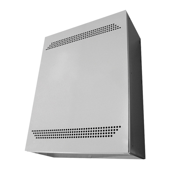
The Phoenix Lite series is a single-phase, standby, Solid-state inverter system
utilizing DSP/PWM technology. The unit packs all the necessary options and is
quickly and simply installed. The Phoenix Lite is designed to function in conjunction
with the existing building electrical system to provide high-quality surge suppression,
power conditioning, backup power protection and distribution for lighting loads and
other critical loads.
Standard Power Level:
Input Voltage:
Input Voltage Range:
Output Voltage:
Output Voltage Regulation:
Output Frequency Range:
Output Wave Form:
Crest Factor:
Input Protection:
Output Protection:
Surge Protection:
Battery:
Recharge Current:
External Battery:
Efficiency:
Audible Noise:
Operating Temperature:
Storage Temperature:
Humidity:
Monitoring:
ORDERING INFORMATION Example: PHXLTE-525-480-120-RP-90
Series
Power Rating
PHXLTE
525 = 525W
700 = 700W
875 = 875W
1050 = 1050W
Notes
1
Some options may not be used together - Consult factory
2
One ECM is used per switching device or circuit
3
Consult factory for warranty options
525, 700, 875, 1050W
120, 208, 240, 277, 480VAC
10% to 15%
120, 277, 120/240 or 120/277VAC
±5% for all loads and battery discharge mode
60 Hz, ±1%
Sine-wave <5% @ 100% linear load
:1 typical
2.5
Input Main Circuit Breaker
Output Main Circuit Breaker
The unit will protect itself and the load against
surges defined in ANSI/EEE C62.45 category A/B
Sealed maintenance-free (AGM) lead calcium
Conforms to UL 924 standards
Provision for hardware connection of external
battery cabinets or DC source
≥99% at 100% linear load
<45dBA
0º to 40ºC (32º to 104ºF)
-20º to 60ºC (-4º to 140ºF)
5 - 95%, Non-condensing
LED Displays Alarms and Diagnostics
Input Voltage
Output Voltage
120 = 120VAC
120 = 120VAC
208 = 208VAC
277 = 277VAC
240 = 240VAC
120/240 = 120/240VAC
277 = 277VAC
120/277 = 120/277VAC
480 = 480VAC
PHOENIX LITE Series
Single Phase, Indoor, Standby Emergency Lighting Inverter
Model:
Accessories:
1
Options
Blank=None
2
ECM120/#
= 120V Environmental Control Module / Qty
2
ECM277/#
= 277V Environmental Control Module / Qty
3
EW
= Extended Warranty
FCON = Form C Contacts
NOF/V/# = Normally OFF Output Circuit / Voltage / Qty
OCB/V/#/A = Output Circuit Breakers / Voltage / Qty / Amps
OST = Onsite Start-Up
RP = Remote Indicator Panel
Page 1 of 24
Date:
Type:
Job Name:
Run Time
90 = 90 Min (Std)
Advertisement
Table of Contents

Related Manuals for BARRON EXITRONIX PHOENIX LITE Series

Summary of Contents for BARRON EXITRONIX PHOENIX LITE Series
- Page 1 PHOENIX LITE Series Single Phase, Indoor, Standby Emergency Lighting Inverter The Phoenix Lite series is a single-phase, standby, Solid-state inverter system Model: Date: utilizing DSP/PWM technology. The unit packs all the necessary options and is quickly and simply installed. The Phoenix Lite is designed to function in conjunction Accessories: Job Name: with the existing building electrical system to provide high-quality surge suppression,...
-
Page 2: Table Of Contents
TABLE OF CONTENTS TABLE OF CONTENTS ABOUT THIS MANUAL Section How to use this manual IMPORTANT SAFETY INSTRUCTIONS Section notes and safety information CHAPTER 1 INTRODUCTION Section 1.1. general Section 1.2. definitions Section 1.3. theory of operation Section 1.4. output loads CHAPTER 2 SPECIFICATIONS Table 1—specifications Section 2.1. - Page 3 Section 5.3. manual bypass switch description Section 5.4. input and output power requirements/connections Section 5.5. system current ratings Section 5.6. grounding CHAPTER 6 INSTALLATION Section 6.1 installing batteries Figure 2—battery connection Section 6.2. input power connections Section 6.3. output power connections Figure 3—input/output current ratings CHAPTER 7.
-
Page 4: About This Manual
While every precaution has been made to ensure accuracy and completeness in this manual, Barron assumes no responsibility and disclaims all liability for damages resulting from the use of this information or for any errors or omissions. -
Page 5: Important Safety Instructions
A Note notice icon indicates when the user should make a reference of infor- mation regarding the UPS operation, load status and display status. Such infor- NOTE: mation is essential if Barron field service assistance and correspondence is required. ENSURE THAT NO FLUIDS OR OTHER FOREIGN OBJECTS CAN ENTER THE IN- VERTER SYSTEM. -
Page 6: Section Notes And Safety Information
ELEC- TRICIAN WHO IS EXPERIENCED IN WIRING THIS TYPE OF EQUIPMENT. CAUSE DAM- AGE TO THE EQUIPMENTS, INJURY OR DEATH OF PERSONNEL. MAKING ANY ELECTRI- CAL CONNECTIONS. THIS EQUIPMENT GENERATES, USES, AND CAN RADIATE RADIO FREQUENCY ENERGY, AND, IF NOT INSTALLED AND USED IN ACCORDANCE WITH THIS MAN- UAL, MAY CAUSE INTERFERENCE TO RADIO COMMUNICATIONS. - Page 7 EXPLOSION, FIRE, EQUIPMENT FAILURE, OR ELECTROCUTION. PRIOR TO CONNECTING THE BATTERY CABINETS TO THE UPS UNIT. TO PREVENT AN ACCIDENT THAT COULD RE- SULT IN INJURY OR DEATH. RECYCLED RATHER THAN DISCARDED. HARMFUL TO THE SKIN AND EYES AND MAY BE TOXIC. OBSERVED WHEN WORKING ON BATTERIES: Page 7 of 24 800.533.3948 •...
- Page 8 DISCONNECTING BAT- TERY TERMINALS. ARE RE- MOVED DURING INSTALLATION AND MAINTENANCE. FOLLOWED: DO NOT SMOKE WHEN NEAR BATTERIES. DO NOT CAUSE FLAME OR SPARK IN BATTERY AREA. TOUCH- ING BATTERIES BY FIRST TOUCHING A GROUNDED SURFACE. TO REDUCE THE RISK OF ELECTRICAL SHOCK; DISCONNECT THE EMERGEN- CY LIGHTING INVERTER SYSTEM FROM THE MAIN SUPPLY BEFORE IN- STALLING AN INTERFACE SIGNAL CABLE.
-
Page 9: Chapter 1 Introduction
GENERAL The principles of operation described herein are applicable to all models. The Phoenix Lite Emergency Lighting Inverters are manufactured to provide critical power for lighting during a power outage. The Phoenix Lite meets or exceeds the life safety codes of UL924 and UL1778. These codes were established to allow the emergency lighting inverters to provide critical power to the lighting circuits during a power failure. -
Page 10: Section 1.2. Definitions
1.2 DEFINITIONS 1.2.1 UNINTERRUPTIBLE POWER SUPPLY SYSTEM (UPS)- All components within the UPS Module Cabinet and associated batteries, which function as a system to provide continuous AC power to a load. This manual provides an overview of the Phoenix Lite components and their functions. The appearance and purpose of operator controls and indicators is described with procedures for installation, operation, start-up, and shutdown. -
Page 11: Section 1.4. Output Loads
value and the facility power remains off, then the system will assume a FAILURE mode. Response to Input Power Failure for A Standby System When the input power fails, the charger is turned off and the battery bank is transferred, becomes a DC supply source used to drive the inverter circuit, maintaining an uninterrupted AC supply to the protected load. -
Page 12: Chapter 2 Specifications
The Phoenix Lite maintains efficient AC Emergency Power to operate all emergency lighting fixtures at “full- light” output providing superior dependability and security to commercial/industrial environments in a small footprint. The UPS System Label displays the rated kW as well as nominal voltages. There are System Labels located on the interior side of the UPS front door and the exterior side of the unit. -
Page 13: Section 2.8. Diagnostics And Maintenance
complete self diagnostic capabilities and LED Monitoring lighted environment prior to an emer- gency. The power supplies are able to do a 5-minute battery run the first of every month except for New Year’s Day when the test is for 90 minutes. The testing can be enabled by going to the Auto- run screen and selecting Yes or No with the Menu Forward or Menu Reverse button. -
Page 14: Chapter 4 Transportation, Inspection, And Installation
HOW TO TRANSPORT THE SYSTEM If there was any dam-age during transportation; Do Not turn on the unit. Immediately notify the shipping agent/transportation carrier and Barron. The packaging is recyclable; keep it for reuse or please disposed of it Install the Emergency Lighting Inverter System in a protected area with adequate airflow and free from excessive dust. -
Page 15: Chapter 5 Description
Figure 6 is the layouts that will help you find the parts and components in your Emergency Lighting Inverter. Maintenance should only be performed by factory-trained or qualified personnel. Do not attempt to service. If you need technical assistance, please contact Barron. 5.3 MANUAL BYPSS SWITCH DESCRIPTION (NOT APPLICABLE IN A PHOENIX LITE) In most units, this switch is located on the inside of the left door of the system (see Figure 6—System... -
Page 16: Section 5.4. Input And Output Power Requirements/Connections
“High Inrush” type. This is to prevent the breakers from tripping during the startup of the unit and its load. Barron uses only the “High Inrush” type of breaker in its units. Refer to Figure 3 when determining the size of your input and output breakers. - Page 17 After creating each string of batteries, ensure that each string consist of the number of batteries indicated by the battery layout and the measured voltage across the string is within tolerance. If you have any further questions about battery connections please contact Barron Service Depart- ment at 1(877)377-6769.
-
Page 18: Section 6.2. Input Power Connections
6.2. INPUT POWER CONNECTIONS Ensure that the utility power to be connected is rated as on the system label. Make sure the hot, neutral and ground are correctly identified and wired to the input terminal block as designated. 6.3. OUTPUT POWER CONNECTIONS Ensure that the loads to be connected are as listed on the system label, and the hot, neutral and ground are correctly identified and are wired to the output terminal block as designated. - Page 19 Figure 3 Page 19 of 24...
-
Page 20: Chapter 7. Displays
DISPLAY PANEL DESCRIPTION 7.1.2 7.1.3 7.1.1 7.1.4 Figure 4 Displays Refer to Figure 4 for descriptions of the Display Panel’s button and indicators. 7.1.1. – Fault LED (RED): Used as a Warning LED, this indicator is lit whenever the UPS faults. Red flashing every 0.5 seconds indicates that the UPS is in Overload. -
Page 21: Chapter 8 Operation And Procedure
8. OPERATION AND PROCEDURE The initial startup must be done in conjunction with Barron or by a factory authorized technician. PLEASE CALL FOR STARTUP BEFORE APPLYING POWER TO THE UPS! 8.1. START-UP PROCEDURE After making all power and grounding connections to the Emergency Lighting Inverter System; ver- ify that the system is OFF (None of the LEDs are lit). -
Page 22: Chapter 10
Verify that the load ly when AC supply is normal. matches the UPS capability specified in the specs. Contact Barron for service or help. Overload of the UPS. Remove some noncritical load. When power failure, backup time Battery voltage is too low. - Page 23 When insulated grip tools are not available, a method for insulating grips on tools that we use at Barron using Plasti Dip by Performix is illustrated in Figures 5a-f. The illustration is only an example of how to insulate your tools, i.e. you may want to insulate the open end of the wrench.
-
Page 24: Process Figure 6-Phoenix Lite System
System Component Layout Figure 6 Page 24 of 24 800.533.3948 • www.barronltg.com...
Need help?
Do you have a question about the EXITRONIX PHOENIX LITE Series and is the answer not in the manual?
Questions and answers