Table of Contents
Advertisement
Quick Links
Advertisement
Table of Contents

Summary of Contents for SSV IGW/400-UART
- Page 1 IGW/400-UART WLAN Device Server First Steps SSV Embedded Systems Heisterbergallee 72 D-30453 Hannover Phone: +49-(0)511-40000-0 Fax: +49-(0)511-40000-40 Manual Revision: 1.0 E-mail: sales@ist1.de Date: 2005-09-26 For further information regarding our products please visit us at www.ssv-embedded.de...
-
Page 2: Table Of Contents
IGW/400-UART – Content CONTENT INTRODUCTION....................... 3 Block Diagram ..........................3 Features IGW/400-UART......................3 GETTING STARTED......................4 Connecting the WLAN Antenna....................4 Connecting the Plug-in Connector....................5 Connecting the Temperature Sensor SMT-160 ................7 Connecting the Power Supply....................8 Arranging and Testing the WLAN Connection on the PC .............10 Accessing the Temperature Sensor ..................12... -
Page 3: Introduction
Our website contains a lot of technical information, which will be updated in regular pe- riods. Block Diagram Figure 1 shows the block diagram of the IGW/400-UART. UART1 correlates with the RS232 connector (COM1) and the EI/Os correlate with the 14-pin environment interface of the IGW/400-UART. -
Page 4: Getting Started
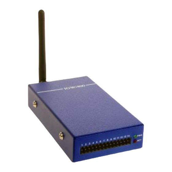
The first step is to connect the WLAN antenna (which is part of the Starter Kit) with the provided interface at the backside of the IGW/400-UART. Please note, that the antenna has to be screwed until stop with the interface. -
Page 5: Connecting The Plug-In Connector
Plug the 14 pin plug-in connector into the corresponding interface at the frontside of the IGW/400-UART. Then connect the two wires of the power supply cable with the 14 pin plug-in connector. For this purpose a screwdriver is needed, which is usually part of the Starter Kit. - Page 6 IGW/400-UART – Getting Started Figure 4: Pin assignment of plug-in connector Wire color Signal black Table 1: Pin assignment of power supply cable Wire color Signal green yellow blue Table 2: Pin assignment of RS232 adapter cable Wire color Signal...
-
Page 7: Connecting The Temperature Sensor Smt-160
Plug now the intelligent temperature sensor SMT-160 on the 9 pin Sub-D connector of the RS232 adapter cable. This sensor delivers temperature data to the RS232 interface of the IGW/400-UART permanently. This data should be transmitted to your PC via WLAN. -
Page 8: Connecting The Power Supply
The IGW/400-UART is now ready for use. Connect the plug-in power supply which is part of the Starter Kit with the connector of the power supply cable. Plug the plug-in power supply into an outlet to provide the IGW/400-UART with power. Check if the red power LED at the frontside is on. - Page 9 IGW/400-UART – Getting Started The IGW/400-UART is now accessible from your PC. Please note the settings of the WLAN interface (ex factory settings). The following table gives an overview. Parameter Setup Value Network Interface WLAN Network Name SSV_IGW400 Ad Hoc Mode Settings...
-
Page 10: Arranging And Testing The Wlan Connection On The Pc
The ad-hoc mode corresponds to a wireless point-to-point connection, e.g. your PC and the IGW/400-UART. The infrastructure mode is needed if you want to connect your PC with a WLAN access point. The software of your PC WLAN extension allows to choose between both operating modes. - Page 11 IGW/400-UART – Getting Started Figure 9: Testing the WLAN connection with ping The IP address of the IGW/400-UART is set ex factory to 192.168.3.126. Open a window with a command prompt on your PC and enter ping 192.168.3.126 The connection between your PC and the IGW/400-UART will be tested. A succesful ping means that there is a running WLAN connection between both systems.
-
Page 12: Accessing The Temperature Sensor
SMT-160 via WLAN. Figure 10: Accessing the temperature sensor The simplest way to access the IGW/400-UART is Telnet. Open a window with a com- mand prompt on your PC and enter telnet 192.168.3.126 10002... -
Page 13: Contact
‘as is’ without warranty of any kind. Some names within this document can be trademarks of their respective holders. © 2005 SSV EMBEDDED SYSTEMS. All rights reserved. S S V E M B E D D E D S Y S T E M S...
Need help?
Do you have a question about the IGW/400-UART and is the answer not in the manual?
Questions and answers