Advertisement
Model - LD160 Series
The LD160 is a single channel inductive loop detector designed for traffic
control applications.
The detector is connected to an inductive loop mounted in the road surface.
When vehicles pass over the loop the detector switches on an output.
The use of microprocessor and surface mount technology enables a large
number of functions to be incorporated into a small package. The LD160 is
compatible with most single channel detectors on the market and is easy to
set-up and install.
Applications
Typical applications in the traffic environment are traffic control (traffic lights), toll systems and vehicle counting.
Features
Reset Switch. Pressing the reset switch enables the detector to be manually reset during commissioning and
testing. This results in the detector re-tuning the sensing loop and becoming ready for vehicle detection.
Switch selectable Sensitivity. The detect sensitivity is the minimum change in inductance required to produce a
detect output. (%∆L/L). Eight sensitivity settings are available on the switches to allow flexibility in configuration.
Switch selectable Frequency. Two frequency settings are available to prevent cross-talk between adjacent
loops.
Fault Relay feature. The Fault relay is activated when a fault has occurred on the loop.
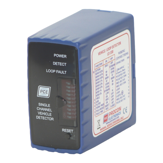
Indicators
Power Indicator. This LED Indicator illuminates when power is present.
Detect Indicator. This LED Indicator is illuminated when there is a vehicle over the loop or the loop is faulty. This
LED can also be used to determine the loop frequency. On reset, count the number of times the LED flashes.
Multiply this number by 10KHz.For example: if the LED flashes 6 times, then the loop frequency is between
60KHz and 70KHz.
Loop Fault Indicator. This LED Indicator is illuminated when the loop is either open circuit or short circuit and is
used to give a visual indication of a faulty loop.
Single Channel Loop Detector
1
Advertisement
Table of Contents

Subscribe to Our Youtube Channel
Related Manuals for Procon LD160 Series

Summary of Contents for Procon LD160 Series
- Page 1 Single Channel Loop Detector Model - LD160 Series The LD160 is a single channel inductive loop detector designed for traffic control applications. The detector is connected to an inductive loop mounted in the road surface. When vehicles pass over the loop the detector switches on an output.
-
Page 2: Technical Specifications
Technical Specifications LD160 200 - 260VAC 50Hz 1.5VA Power supply LD161 100 - 120VAC 60Hz 1.5VA 11 - 26VAC/DC 50/60Hz 95mA max. LD162 0.5A/220VAC . (Fail Safe - The channel output will go into detect if a Presence Relay loop fault is detected or the power fails.) 0.5A/220VAC (The fault output will indicate a fault during a loop fault or Fault Relay power fail.) -
Page 3: Switch Settings
Switch Settings LD160 Switch Settings Switch No. Function 2,3,4 Sensitivity 0.02% S2/S3/S4 2,3,4 Sensitivity 0.01% S2/S3 2,3,4 Sensitivity 0.05% S2/S4 2,3,4 Sensitivity 0.1% S3/S4 2,3,4 Sensitivity 0.2% S3/S4 2,3,4 Sensitivity 0.5% S2/S4 2,3,4 Sensitivity 1% S2/S3 2,3,4 Sensitivity 2% S2/S3/S4 Frequency High Relay Functionality... -
Page 4: Wiring Diagram
Diagnostics SYMPTOM POSSIBLE CAUSE SOLUTION The POWER LED is not No power supply voltage on Check that the power supply is the input. correctly wired to the detector. (PINS 1 and 2) The DETECT LED flashes There may be a poor Check all wiring. - Page 5 Loop Installation Guide 1. The detector should be installed in a waterproof housing as close to the loop as possible. 2. The loop and feeder should be made from insulated copper wire with a minimum cross-sectional area of 1.5mm . The feeder should be twisted with at least 20 turns per metre. Joints in the wire are not recommended and must be soldered and made waterproof.
-
Page 6: Contact Details
Powering up and testing the LD160 Switch on the power and observe the lights on the front of the detector. The top light is an indication of power. This light must always be on. The middle light indicates if there is a vehicle present on the loop. When the power is first applied to the detector this light flashes a couple of times indicating that the detector has tuned to the loop.
Need help?
Do you have a question about the LD160 Series and is the answer not in the manual?
Questions and answers