Advertisement
WSC7500
Workstation Corner
Accessory
Congratulations on your purchase of the WSC7500 Workstation
Corner Accessory! Please read the following instructions carefully.
We hope you enjoy your new purchase.
Components
*Parts not drawn to scale.
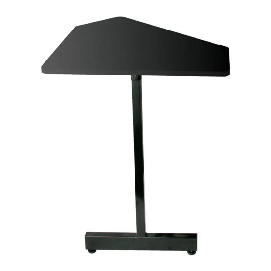
A. Work Surface
B. Metal Leg
Also included: Allen Wrench
Tools Required: Level, Hammer, #2 Phillips Head Screw Driver, & 3/8 Wrench, Transparent Tape
Assembly Instructions
Preparing the Work Surface:
Note: The Corner Accessory work surface is laminated on both sides and NOT pre-drilled to
allow the flexibility of attaching to either the left or right side of your WS7500 Workstation.
1. Depending on location in the room, decide which side of the Workstation you
intend on placing the Corner Accessory and mark one side of the work surface (A) as
the TOP with transparent tape. (Instructions will show the work surface installed on
the left side of the WS7500 workstation.)
2. Tape the hole location template (C) to the surface opposite the TOP side.
3. Before creating the holes with the nail (Z1) (included in the hardware kit), ensure
that the 6 holes for the brackets match correctly.
4. Mark nail using tape approximately 1/8" from the tip as a guide. Tap the nail
approximately 1/8" into the surface with a hammer to create 14 starter holes.
Remove template. (Figure A).
5. Align the leg mounting plate (D) and fasten using 8 wood screws (Z4) with the #2
Phillips Head Screwdriver. (DO NOT overtighten.) (Figure B).
6. Align both mounting plates (F) and fasten each plate with 3 wood screws (Z4).
(DO NOT fully tighten the screws.) (Figure B).
CAUTION
FAILURE TO OBSERVE PROPER ASSEMBLY INSTRUCTIONS, EXCEEDING THE
WEIGHT CAPACITY OR FAILURE TO OBSERVE THE WARNINGS AS MENTIONED
IN THIS INSERT MAY CAUSE STAND TO COLLAPSE, BODILY INJURY OR
EQUIPMENT DAMAGE AND WILL VOID THE PRODUCT WARRANTY.
C. Hole Location Template
Z1. Nail
Z2. Bolt
Visit On-Stage for the most recently-updated instructions.
D. Leg Mounting Plate
Z3. Locking Nut
Z4. Wood
Screws (x20)
STANDS
E. Mounting Plates (x2)
Z5. Rubber
Feet (x2)
Figure A
Figure B
Advertisement
Table of Contents

Summary of Contents for on stage WSC7500
- Page 1 WSC7500 STANDS Workstation Corner Accessory Congratulations on your purchase of the WSC7500 Workstation Corner Accessory! Please read the following instructions carefully. We hope you enjoy your new purchase. Components *Parts not drawn to scale. C. Hole Location Template D. Leg Mounting Plate E.
- Page 2 The WSC7500 weight capacity is 75lbs. Optional Workspace Configurations with the WSC7500 The WSC7500 Corner Accessory can be attached to either side of the WS7500 to create the ideal workstation. Illustrated below are just a few possible op- tions. Ask your dealer about the WSR7500 Rack Cabinet (sold separately) to complete your work environment.
Need help?
Do you have a question about the WSC7500 and is the answer not in the manual?
Questions and answers