Table of Contents
Advertisement
Quick Links
Processor
OPERATION MANUAL
VP-7000
Thank you for purchasing our product. Read this
manual carefully before use to avoid unexpected
accidents and to take full advantage of the
product's capabilities.
897N120547D
English
Introduction
1
Precautions
2
System Confi guration
Name and Function of Each
3
Part
System Installation and Initial
4
Settings
5
Function Settings
Preparation and Inspection of
6
the System
7
Method of Use
8
Image Recording
9
Storage and Maintenance
10
Troubleshooting
11
Main Specifi cation
Advertisement
Table of Contents

Related Manuals for FujiFilm VP-7000

Summary of Contents for FujiFilm VP-7000
- Page 1 System Method of Use Image Recording Storage and Maintenance Troubleshooting Main Specifi cation VP-7000 Thank you for purchasing our product. Read this manual carefully before use to avoid unexpected accidents and to take full advantage of the product's capabilities. 897N120547D...
- Page 2 897N120547D...
-
Page 3: Contents At A Glance
Contents at a Glance Introduction Read and understand this manual fully before using this product. 1 Precautions Chapter This chapter describes the warnings and cautions for safe operation of this product. 2 System Configuration Chapter This chapter describes the equipment used in combination with this product. 3 Name and Function of Each Part Chapter This chapter describes the name and function of each part of this product. -
Page 4: Table Of Contents
Contents Contents Contents at a Glance ......................iii Introduction About This Manual ......................1 ♦ Operation Manuals ..................2 How to Read This Manual ....................3 ♦ Terms ......................3 ♦ Conventions Used in This Manual ............3 Chapter 1 Precautions Safety ........................1-1 ♦ Category of Equipment .................1-1 1.1.1 Infection ....................1-2 1.1.2... - Page 5 Chapter 2 System Configuration Checking Package Components ................2-1 ♦ Package Components ................2-1 Equipment Using in Combination ................2-2 2.3 Standard System Configuration ................2-3 System Expansion ....................2-4 Chapter 3 Name and Function of Each Part Front Panel ......................3-1 Rear Panel ......................3-3 Side Panel ......................3-5 Keyboard .......................3-6 Socket Protection Cap ...................3-9 Symbols .........................3-9...
- Page 6 Contents 4.2.5 Basic Setting Tab ...................4-29 4.2.6 Light Source Tab ..................4-31 4.2.7 Endoscope Tab ..................4-32 4.2.8 Setting Foot Switch (FS1) ...............4-44 4.2.9 Setup for Switching the Shutter Speed During Optical Zoom....4-47 4.2.10 Setting the Doctor's Name ..............4-48 4.2.11 Setting the Procedure Name ..............4-54 4.2.12 Setting the Message ................4-58 Security Function ....................4-62 4.3.1...
- Page 7 5.5.4 Setting Freeze Mode ................5-59 5.5.5 Setting Multi Zoom Mode ................5-61 5.5.6 Lap Time Display ..................5-62 Chapter 6 Preparation and Inspection of the System Installing and Connecting the Equipment ..............6-1 Preparing Related Equipment ................6-1 Operation Check of Light Source and Processor ..........6-2 Registering and Calling Adjustment Value ............6-7 Registering the Patient Information ...............6-7 Calling up the Patient Information ................6-8...
- Page 8 Contents Printing the Image with the Color Printer (Remote System) ........8-1 8.2.1 Assignment of Image Capture Switches ...........8-2 8.2.2 Printer Setting ...................8-2 8.2.3 Capturing the Image .................8-3 8.2.4 Printing the Image ..................8-5 Printing the Image with the Color Printer (RS-232C System) ........8-6 8.3.1 Assignment of Image Capture Switches ...........8-7 8.3.2...
- Page 9 Storage ........................9-3 Relocation ......................9-4 Chapter 10 Troubleshooting 10-1 10.1 Troubleshooting ....................10-1 10.2 Error Messages ....................10-4 Chapter 11 Main Specification 11-1 11.1 Specification ......................11-1 ♦ Classification of Medical Electrical Equipment ........11-1 ♦ Applied Part ..................11-1 ♦ Specification ..................11-1 ♦ Operating Environment ..............11-2 ♦ Transport and Storage Environment ..........11-2 ♦...
- Page 10 Contents 897N120547D...
-
Page 11: Introduction
Read and understand this manual carefully before operating the equipment. About This Manual This manual provides necessary information for using the VP-7000 processor, such as the operation procedures, settings and how to install the system. If you are a first-time user of this product, be sure to read this manual before actual operation. -
Page 12: Operation Manuals
• FUJIFILM Corporation shall not be liable for malfunctions or damages resulting from use under environment conditions outside the range specifi ed for this product, such as the power supply, installation environment, etc., as described in this manual. -
Page 13: Terms
How to Read This Manual ♦ Terms Term Description Reprocessing It refers to disinfection or sterilization performed after the manual cleaning of the endoscope and its accessories. This product If refers to the processor. Standard accessory It refers to the parts and devices included in the package or supplied with this product. - Page 14 897N120547D...
-
Page 15: Precautions
• Do not modify this product or its components, and do not disassemble, repair or in any other ay reverse engineer these products. Even if you find a defect, do not attempt to repair these products yourself. FUJIFILM Corporation shall not be liable for any defects or device failures caused by such modifications, disassembly, repairs or reverse engineering. -
Page 16: Direct Harm To Human Body
Chapter 1 Precautions In ection 1.1.1 WARNING • eplace the cover for a keyboard to hich any bodily fluid droplet, etc., has adhered. here is a risk of infection. irect Harm to Human ody 1.1.2 WARNING • If any peripherals not described in “2.2 Equipment Using in Combination” are used, this product may not function properly and it may cause damage to the peripherals or injury to patients or physicians. -
Page 17: Cautions/Warnings
Intended se 1.2.1 WARNING • This product is intended to be used in combination with a FUJIFILM medical endoscope, light source, monitor, recorder and various peripherals for observation, diagnosis, endoscopic treatment, and image recording in medical facilities under the management of physicians. -
Page 18: Loss Of Function
Chapter 1 Precautions oss o Function 1.2.5 CAUTION • During an examination, if the endoscopic image disappears, a live image is not displayed after freeze mode has been cancelled, or the endoscopic image is discolored, reset the processor and light source. •... -
Page 19: Installation Of Equipment
1.2.7 Installation of equipment WARNING • o avoid electric shock and equipment toppling over, observe the follo ing precautions when installing the equipment. < o avoid electric shock • Connect the power plugs of the processor and light source directly to the receptacles for the processor/light source on the cart. -
Page 20: Electric Shock
1.2.11 Foreign Matter and i uid WARNING • Foreign matter, ater and chemicals entering the equipment may cause a fire or electric shock. In such a case, stop using the equipment immediately, disconnect the po er plug from the power outlet, and consult your local FUJIFILM dealer. 1.2.12 High oltage CAUTION • This product has high voltage portions. No one except service personnel should touch the inside. -
Page 21: Preparation And Inspection Before Use
CAUTION • This product has components that contain a lithium manganese dioxide battery and other materials that may cause environmental pollution. Follow the legal procedures when discarding the product. For details, consult your local FUJIFILM dealer. 1.2.18 Security Function CAUTION •... -
Page 22: Handling Of Endoscope
Chapter 1 Precautions otential e uali ation 1.2.19 • This system is equipped with an equipotential terminal. Use this terminal when equipotential grounding is required at the hospital or clinic. 1.2.20 Handling o ndoscope • Wear rubber gloves when handling the Endoscope to prevent infection and electrostatic discharge. 1.2.21 System ersion •... -
Page 23: System Configuration
If a component is damaged, or if a component is missing, contact your local FUJIFILM dealer. ♦ Package Components Note • he type of the data keyboard varies depending on the country. • he figure in parentheses indicates the quantity. Socket rotection Cap CC-203 (1) Processor VP-7000 (1) o er Cord 1 ata eyboard DK-7000U (1) or DK-7000E (1) peration Manual 1 897N120547D... -
Page 24: Equipment Using In Combination
Equipment Using in Combination he equipment used in combination ith the processor and the light source is sho n in the table blo . able 2.1 Equipment configuring the standard system Type Model name Processor VP-7000 Light Source [Note1] ata eyboard DK-7000U or DK-7000E Endoscope 700 system scopes system scopes,... -
Page 25: Standard System Configuration
• hen the series scope is used, place the processor on the lo er shelf and the L light source on the upper shelf. ther ise, it may cause malfunction of the endoscope. Water Tank Processor VP-7000 LC Monitor CL 22 CL 2 Light Source CCL22 CCL2 Endoscope 700 System Scope 600 System Scope... -
Page 26: System Expansion
Endoscopic treatment Ultrasonic e amination ecording of video images rinting of still images Ultrasonic rocessor SU-1 Endoscope 700 System Scope 600 System Scope System Scope Processor ata keyboard VP-7000 DK-7000U or DK-7000E Light Source Water Tank WT-4 WT-603 Cart 897N120547D... - Page 27 Note • For details on the connections of peripherals other than listed here, consult your local FUJIFILM dealer. Electrosurgical Unit ICC 2 LC Monitor CL 22 FUJIFILM CL 2 FUJIFILM CCL22 J C E CCL2 J C E rinter U 2 M S M S 2 M S ideo ecorder M S...
- Page 28 897N120547D...
-
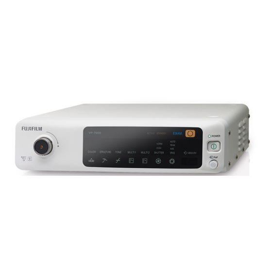
Page 29: Name And Function Of Each Part
Chapter Name and Function of Each Part Front Panel 1. Electrical Connector Socket Used to connect the electrical connector of the 600 system scope or 500 system scope. 2. EXAM. Button/EXAM. Indicator Lamp Used to turn the power to the endoscope ON and OFF. Power to the Endoscope ON: The ACTIVE indicator lamp lights up in blue. - Page 30 Chapter 3 Name and Function of Each Part 3. Network Access Indicator Lamp Displays the connection status of the network. • During connection: Lights up in green. • During communication: Flashes in orange. • When the communication fails: Lights up in orange. 4.
-
Page 31: Rear Panel
13. Color Adjustment Button Adjusts the color. “5.3.5 Color Adjustment Settings” Rear Panel 1. Fuse Holder Contains two T3.15AH 250V fuses. 2. Power Supply Connector Used to connect the attached power cord. 3. Potential Equalization Terminal hen necessary for safety, this terminal is connected to a potential equali ation terminal on a peripheral device to equalize the potential between this product and the peripheral device. 4. - Page 32 Chapter 3 Name and Function of Each Part 8. DVI-D Connector Used to connect the LCD monitor via a monitor cable. Digital image signals are output from this connector. 9. S Video Connector Outputs a component signal separated into a Y signal for brightness and a C signal for color. 10.
-
Page 33: Side Panel
Side Panel <Left side> <Right side> 1. Ventilation Holes entilation holes. eep holes 1 mm or more a ay from any ob ects. 897N120547D... -
Page 34: Keyboard
Chapter 3 Name and Function of Each Part Keyboard 10 11 12 13 14 <Data control keys> 1. [Patient Entry] key Displays the Patient Information Entry screen. 2. [Patient] key Displays the Patient List screen. 3. [Doctor] key Displays the Doctor List screen. 4. - Page 35 <Peripheral device control keys> 9. [System] key Displays the System Setup screen. 10. [Peripherals] key Selects and performs the settings for the peripheral devices to be used with this product. 11. [Image] key Displays the Image Setup Page screen. 12. [Panel] key Performs the initial settings for the functions assigned to the front panel of this product.
- Page 36 Chapter 3 Name and Function of Each Part 20. [Delete] key Deletes the character at the location of the cursor. When a list of patient data is displayed : The selected patient data is deleted. When a list of doctor names is displayed : The selected doctor name is deleted. When a list of procedure names is displayed : The selected procedure name is deleted.
-
Page 37: Socket Protection Cap
Socket Protection Cap 1. Socket Protection Cap for Electrical Connector Covers the socket when the 600 system scope or 500 system scope is not connected. Note henever the system scope is used, attach the protection cap. Symbols Symbol Description Serial number Year of manufacture Manufacturer Authorized representative in the European Community Consult instructions for use Temperature limitation eep dry... -
Page 38: Data Display On The Observation Screen
Chapter 3 Name and Function of Each Part Data Display on the Observation Screen hen the light source is used, three types of special light can be used for observation in addition to the normal light (“Normal mode”). bservation modes using special light are called LI , LI bright and LCI . n the monitor, they are displayed as LI , LI brt and LCI , respectively. <Type of the observation screen (Mask Type: Type 1)> •... - Page 39 <Type of the observation screen (Mask Type: Type 2/Dual Mode)> hen FICE is on, the FICE image is displayed in the main screen and the normal image is displayed in the sub-screen. Note hen the observation mode is LI, LI bright or LCI, no image is displayed in the sub-screen even if “Type 2/Dual Mode”...
- Page 40 Chapter 3 Name and Function of Each Part <Information displayed on the observation screen (Mask Type: Type 1)> Data to be displayed is different depending on the settings. Setting the data to be displayed should be performed by service personnel. 10 11 12 10 11 12 14 3-12...
- Page 41 <Information displayed on the observation screen (Mask Type: Type 2)> Data to be displayed is different depending on the settings. Setting the data to be displayed should be performed by service personnel. 10 11 12 22 20 1. Timer 2. Date 3.
- Page 42 Chapter 3 Name and Function of Each Part 6. Focus Indicator Displayed when an optical zoom scope is connected. 7. Electronic Zoom Ratio x1.00 to 2.00 or x1.00 to 1.75 (0.05 step) Note The zoom ratio of some 530 series scopes is x1.00 to 1.95. 8.
- Page 43 21. Number of Captured Images 22. Printer Status The status is displayed as follows (only for digital printer): When the printer is used: Memory status: When the printer is not used: Nothing is displayed. 23. DICOM Server Connection Status The connection status with the DICOM server is displayed as follows: S: Storage status of a (stored) image M: Connection status of the worklist P: MPPS (progress of an examination)
- Page 44 Chapter 3 Name and Function of Each Part <Example of information displayed on the video output screen> Note hen the monitor is connected to the , ideo, or S ideo connector, do not use such an image for the main observation. epending on the monitor type, the periphery of the screen may not be displayed. In this case, set the monitor in the under scan mode. In the case of Normal mode: 06:52:30 PM HN S RC FICE*1 -4+4...
- Page 45 1. Hyper-Tone and Noise Reduction Hyper-tone (HT) and noise reduction (NR) are displayed as follows. (The setting is indicated in parentheses.) ot displayed no setting , hite Lo , green Mid , and yello Installation should be performed by service personnel. 2. Iris Mode “7.13 Switching the Iris Mode” 3.
- Page 46 Chapter 3 Name and Function of Each Part 17. Hospital Name 18. Timer 19. Time 20. Date 21. Special Light Observation Mode LI , LI bright or LCI is displayed. 3-18 897N120547D...
-
Page 47: Displaying Fice Set
Displaying FICE Set hen the ageUp key is pressed ith FICE turned , FICE set is displayed on the screen. y pressing the ageUp key again, FICE set disappears. In the case of SXGA mode: In the case of FullHD mode: 3-19 897N120547D... - Page 48 Chapter 3 Name and Function of Each Part When the monitor is connected to the RGB TV (NTSC/PAL), Video, or S Video connector: 06:52:30 PM HN S RC FICE*1 -4+4 R 500nm G 510nm B 500nm Rgain 3 Ggain 4 Bgain 3 1.
-
Page 49: Patient Info. + Scope Info. Dialog
Patient Info. + Scope Info. Dialog hen registering the ne patient information or s itching the patient information, the atient Info. Scope Info. dialog is displayed. nozzle In the patient information area, the information registered in the atient Information Entry screen is displayed. - Page 50 3-22 897N120547D...
-
Page 51: System Installation And Initial Settings
• Use the rated voltage only. ot doing so may cause a fire, electric shock or malfunction. • When the 590 series scope is used, place the VP-7000 processor on the lower shelf and the BL-7000 light source on the upper shelf. Otherwise, it may cause malfunction of the endoscope. -
Page 52: Installation Flowchart
Note • Do not block ventilation holes. Doing so may cause overheat on equipment. • Connect the power plug of the VP-7000 processor directly to the receptacles for the processor/light source on the cart. • When a peripheral for system expansion is installed, restart the VP-7000 processor. -
Page 53: Installation Onto The Cart (Standard System Installation Example)
4.1.2 Installation onto the Cart (Standard System Installation Example) LCD Monitor: CL-22 CL-24 CCL22 CCL2 Processor: VP-7000 CC7-101 Data Keyboard: DK-7000U or DK-7000E Light Source: BL-7000 897N120547D... - Page 54 Place one hand under one side of the bottom of the light source and lift it up. Note When the 590 series scope is used, the VP-7000 processor is placed on the lower shelf and the BL-7000 light source is placed on the upper shelf. Place the VP-7000 on the lo er shelf first. 897N120547D...
- Page 55 While lifting the bottom up, place the other hand under the bottom of the front panel. In the same manner, the other person lifts up the other side of the unit. Hold the unit steadily using two persons. 897N120547D...
- Page 56 Chapter 4 System Installation and Initial Settings Gently place the light source onto the movable shelf. Note To avoid falling off the cart, make sure that the feet of the light source are placed inside the stoppers on the movable shelf. Gently place the light source onto the processor.
- Page 57 Note To avoid falling off the cart, make sure that the feet of the processor are placed inside the dents on the light source. When installing the processor, keep the distance more than 17 mm between the side and rear surfaces and the wall. 17mm 17mm 17mm...
-
Page 58: Connecting The Light Source
4.1.3 Connecting the Light Source Connect the interface cable connector on the processor and that on the light source using the CC7-101 interface cable. Processor: VP-7000 Light Source: CC7-101 BL-7000 Note After all devices are connected, connect the power cord. -
Page 59: Connecting The Monitor
• For details on how to install the LCD monitor onto the monitor arm of the cart, refer to the operation manual of the cart. LCD Monitor: CL-22 CL-24 CCL220/AR CCL244/AR Processor: VP-7000 Note After all devices are connected, connect the power cord. “4.1.11 Connecting the Power Source” 897N120547D... -
Page 60: Connecting The Keyboard
• The type of the data keyboard varies depending on the country. • For details on how to install the keyboard onto the keyboard tray of the cart, refer to the operation manual of the cart. Processor: VP-7000 Data Keyboard: DK-7000U or DK-7000E Note After all devices are connected, connect the power cord. -
Page 61: Installation For System Expansion
The image below is an example of the expanded system in which a printer and video recorder are mounted. When operating an electric bed, it may hit against the scope connector of the endoscope connected to the light source, causing damage to the devices. VP-7000 BL-7000 Example of Installation WARNING When mounting peripherals on the cart, observe the following precautions. - Page 62 <Example of Expanded System Connections> LCD Monitor: CL-22 CL-24 CCL220/AR Color Printer: CCL244/AR UP-25MD BNC-01, 03, 05 CC2-903 Processor: VP-7000 CC5-301 CC3-601, 603, 608 CR-05 Digital Printer: UP-D25MD CR-05 Video Recorder: HVO-550MD CC7-101 Light Source: BL-7000...
-
Page 63: Printer Connection (Remote System)
When the image output from the processor is displayed on the monitor via the printer, the image may flicker or disappear. Connect the monitor used as the main observation screen directly to the processor. <Connection 1> When the image is captured by using the switch of Endoscope Color Printer: UP-25MD CC3-601, 603, 608 BNC-01, 03, 05 CC2-903 Processor: VP-7000 CR-05 4-13 897N120547D... - Page 64 <Connection 2> When the image is captured by the foot switch Color Printer: UP-25MD CC3-601, 603, 608 BNC-01, 03, 05 CC2-903 Processor: VP-7000 Foot Switch CR-05 Note • Use this product in combination with the devices necessary for endoscopic examinations. • After all devices are connected, connect the power cord.
-
Page 65: Printer Connection (Rs-232C System)
<Connection Example> Color Printer: UP-55MD CC3-601,603,608 Processor: VP-7000 Note • Use this product in combination with the devices necessary for endoscopic examinations. • After all devices are connected, connect the power cord. “4.1.11 Connecting the Power Source”... -
Page 66: Digital Printer Connection
Chapter 4 System Installation and Initial Settings 4.1.9 Digital Printer Connection Digital Printer: UP-D25MD Processor: VP-7000 Note • Use this product in combination with the devices necessary for endoscopic examinations. • After all devices are connected, connect the power cord. “4.1.11 Connecting the Power Source”... -
Page 67: Video Recorder Connection (Remote System)
4.1.10 Video Recorder Connection (Remote System) <Connection Example> Video Recorder: HVO-550MD CC5-301 Processor: CR-05 VP-7000 Note • Use this product in combination with the devices necessary for endoscopic examinations. • After all devices are connected, connect the power cord. “4.1.11 Connecting the Power Source” 4-17... -
Page 68: Connecting The Power Source
Chapter 4 System Installation and Initial Settings 4.1.11 Connecting the Power Source Insert the specified power cords into the respective power supply connectors on the processor and the light source, and connect them securely. Note • Do not use the power cord other than the attached one. Make sure that the power cord is correct by checking the model number on the power cord. - Page 69 Connect the power plug of the LCD monitor to the receptacle for peripherals on the cart. Plug the power cord of the cart into a protective earth receptacle. 4-19 897N120547D...
-
Page 70: Power Source
These combinations are determined based on the viewpoint of electrical safety. The performance of the equipment depends on the specifications of the manufacturers. Table 4 1 uipment configuring the system Type Model name Processor VP-7000 [Note] Data Keyboard DK-7000U or DK-7000E Light Source BL-7000 Endoscope 700 system scopes, 600 system scopes, 500 system scopes [Note] The type of the data keyboard varies depending on the country. -
Page 71: Connecting The Power Source When Using The Cart
Table 4 uipment configuring the system Type Model name LCD Monitor CL-22 (FUJIFILM), CL-24 (FUJIFILM), CCL22 J C E CCL2 J C E Printer UP-25MD (SONY), UP-55MD (SONY), UP-D25MD (SONY) ideo ecorder HVO-1000MD (SONY), HVO-550MD (SONY) 4.1.13 Connecting the Power Source When Using the Cart The cart is equipped with two types of receptacles;... -
Page 72: Basic Information On Power Cord
Chapter 4 System Installation and Initial Settings 4.1.14 Basic Information on Power Cord Device connector IEC 60320-1 C13 1.0mm2 or more, 3 wires (200V input) Cross-section area of cable 16AWG or more, 3 wires (USA) 100V to 120V: 125VAC or more Input voltage More than 120V to 240V: 250VAC or more USA: 13A or more... -
Page 73: Initial Settings At The Time Of Installation
Initial Settings at the Time of Installation This section explains the initial settings of the system. Note During the observation, the observation screen is displayed in the sub-screen at the lower right side of the setup screen. 4.2.1 Flowchart of System Settings at the Time of Installation he flo chart of system settings at the time of installation is described belo . efer to each section by follo ing this flo chart. -
Page 74: Basic System Setup Operations
Chapter 4 System Installation and Initial Settings 4.2.2 Basic System Setup Operations Press the [System] key on the keyboard. The System Setup screen appears. Note • Essentially the same operation applies to other setup keys. • During the observation, the observation screen is displayed in the sub-screen at the lower right side of the setup screen. -
Page 75: Function Tab
To change the value of an item, select the item and press the [Enter] key. This enables you to select a different value or directly enter the desired value. Note • Use the and keys to select a value. • For the items with a “ ↲ ” mark at the right end, a submenu is displayed. •... - Page 76 Chapter 4 System Installation and Initial Settings Category Item Value Description Multi Button Multi Button 1 FICE Set the function to be assigned to the Multi Button 2 “Multi 1” or “Multi 2” button on the front eset panel of the processor. Timer After the setting is completed, press the Lap Time...
-
Page 77: Display Tab
Category Item Value Description Zoom Setup Multi Zoom Continuous Set the type of zoom operation that Mode is applied when an endoscope with 5 Step the optical zoom function is used in 3 Step combination with this product. 2 Step emarks This item needs to be set by service personnel. - Page 78 Chapter 4 System Installation and Initial Settings Category Item Value Description Space Key Screen display Patient info. OFF Select the type of data that is displayed switching or hidden on the observation screen each Observation mode only time the [Space] key is pressed. All OFF emarks When “Patient info.
-
Page 79: Basic Setting Tab
4.2.5 Basic Setting Tab CAUTION • hen a non Full monitor is used, if Full is selected in Screen esolution , the image is not displayed properly on the monitor. If this happens, press the [Ctrl], [Alt] and [S] keys at the same time. The screen resolution setting changes to “SXGA” and a buzzer sounds. - Page 80 • When a Full HD wide monitor compatible with this product is used, the screen can be displayed in Full HD. For details on the monitor in use and how to change the setting, consult your local FUJIFILM dealer.
-
Page 81: Light Source Tab
4.2.6 Light Source Tab System Setup Function Display Basic setting Light source Endoscope Light Src Setup Pump Level : Hi Pump Off (minute) : Save and Exit [↓] [↑] Move [Enter] Select [Esc] Cancel Category Item Value Description Light Src Setup Pump Level Set the pump setting at the beginning of an examination. -
Page 82: Endoscope Tab
Chapter 4 System Installation and Initial Settings 4.2.7 Endoscope Tab System Setup System Setup Function Display Basic setting Light source Endoscope Free e Mode Setup Free e Mode : Free e / Tri er Scope Switch Setup In o on Connected Scope 700 System :... - Page 83 Category Item Value Description 700 System “<Functions to be The freeze mode “F/T” or “F+T” can be Opt. Zoom assigned to the scope set. Freeze Mode switch>” “• Assignments of 700 System F/T F+T (5-Switch) Scope” Not Assigned Trigger ecord 700 System “<Functions to be nly the free e mode F...
- Page 84 “4.2.2 Basic System Setup Operations” <Functions to be assigned to the scope switch> The functions described in the following chart can be assigned to the scope switches of the endoscope connected to the VP-7000. The setting is performed by service personnel. Function Description...
- Page 85 Function Description Shutter Speed This switch changes the shutter speed set on the Shutter Speed Setup screen. “5.3.6 Setting the Shutter Speed” Obs. Mode Preset his s itch changes the observation mode in the order specified on the Obs. Mode Preset Setup. . .1 egistering, Calling Up and Editing and eleting Image Setup age egistering Image Setup age Scope Common tab - Obs.
- Page 86 Chapter 4 System Installation and Initial Settings Function Description PoP ON This switch displays PoP. PoP Display Format This switch changes the display format of PoP. Lap Time When this switch is pressed, the lap time displayed on the observation screen is started/stopped/reset. “7.15.4 Lap Time Function”...
- Page 87 <Scope Switch Setting> The functions available for each scope switch are described in the following chart. The setting is performed by service personnel. • Assignments of 700 System (5-Switch) Scope Function F/T (Freeze / Trigger) F+T (Freeze + Trigger) Free e [Note 1] Trigger [Note 1]...
- Page 88 Chapter 4 System Installation and Initial Settings • Assignments of 700 System (4-Switch) Scope Function F/T (Freeze / Trigger) F+T (Freeze + Trigger) Free e Trigger ecord Iris Mode Shutter Speed Obs. Mode Preset Structure Emphasis FICE Color Emphasis Display Electronic Zoom Timer PoP ON...
- Page 89 • Assignments of Normal Scope Function F/T (Freeze / Trigger) F+T (Freeze + Trigger) Free e Trigger ecord Iris Mode Shutter Speed Obs. Mode Preset Structure Emphasis FICE Color Emphasis Display Electronic Zoom Timer PoP ON PoP Display Format Lap Time Not Assigned Yes: Available to assign [Note]...
- Page 90 Chapter 4 System Installation and Initial Settings • Assignments of Normal Scope (4-Switch Scope) Function F/T (Freeze / Trigger) F+T (Freeze + Trigger) Free e Trigger ecord Iris Mode Shutter Speed Obs. Mode Preset Structure Emphasis FICE Color Emphasis Display Electronic Zoom Timer PoP ON...
- Page 91 • Assignments of Optical Zoom Scope Note For the endoscopes without the SP switch, the functions for SP switch cannot be selected. Function F/T (Freeze / Trigger) F+T (Freeze + Trigger) Free e Trigger ecord Iris Mode Shutter Speed Obs. Mode Preset Structure Emphasis FICE Color Emphasis...
- Page 92 Chapter 4 System Installation and Initial Settings • Assignments of Ultrasonic Endoscope Function F/T (Freeze / Trigger) F+T (Freeze + Trigger) Free e Trigger ecord Iris Mode Shutter Speed Structure Emphasis FICE Color Emphasis Display Electronic Zoom SU Freeze SU Store Timer PoP ON PoP Display Format...
- Page 93 • Assignments of Ultrasonic Endoscope (5-Switch Scope) Function F/T (Freeze / Trigger) F+T (Freeze + Trigger) Free e Trigger ecord Iris Mode Shutter Speed Structure Emphasis FICE Color Emphasis Display Electronic Zoom SU Freeze SU Store Timer PoP ON PoP Display Format Lap Time Not Assigned Yes: Available to assign...
-
Page 94: Setting Foot Switch (Fs1)
<Functions to be assigned to the foot switch (FS1)> The functions described in the following chart can be assigned to the foot switch of the endoscope connected to the VP-7000. When the function needs to be changed, consult your local FUJIFILM dealer. - Page 95 Function Description Optical Zoom: Zoom In When an optical zoom scope is connected, this switch changes the zoom ratio of the optical zoom. This switch performs zoom-in only. Optical Zoom: Zoom When an optical zoom scope is connected, this switch changes the zoom ratio of the optical zoom.
- Page 96 Chapter 4 System Installation and Initial Settings Setting Foot Switch (FS1) The functions available for each part of the foot switch are described in the following chart. Gray switch Black switch Note For the endoscopes without the SP switch, the functions for SP switch cannot be selected.
-
Page 97: Setup For Switching The Shutter Speed During Optical Zoom
4.2.9 Setup for Switching the Shutter Speed During Optical Zoom When an optical zoom scope is connected, the shutter speed at the optical zoom can be switched automatically. The switching methods are described below. The switching method (Auto/Auto 2/Manual) and the OM max. -
Page 98: Setting The Doctor's Name
Chapter 4 System Installation and Initial Settings 4.2.10 Setting the Doctor's Name This section describes the method of registering a doctor’s name in the doctor list, and also the method of deleting a registered doctor’s name. The registered doctor’s name can be selected when registering patient information. - Page 99 Enter the doctor’s name, using up to 20 characters. octor octor ist 1/2 Ima e settin Doctor Name Freeze Mode Upper GI Lower GI Ot ers 01 01 AOYAMA octor ist 1/2 elete all listed data [↓] [↑] Move [Enter] Select [Insert] Edit [ elete] elete [Esc] Cancel When entry of the doctor name is completed, press the [Enter] key.
- Page 100 Chapter 4 System Installation and Initial Settings Select the image setting. By selecting the image setting according to the target region of endoscopic observation, the appropriate image setting is loaded at the time of starting the examination. When a pop-up menu is displayed, select “* None” or an already registered image setup page name.
- Page 101 Once you have entered all of the doctor’s names, select a doctor name and press the [Enter] key. The settings for the selected doctor are called up and operation returns to the observation screen. To return to the observation screen without the settings called up, press the [Esc] key. octor octor ist 1/2 Ima e settin...
- Page 102 Chapter 4 System Installation and Initial Settings Move the cursor to the number of the doctor’s name to be deleted and press the [Delete] key. he confirmation message his doctor information ill be deleted. appears. octor octor ist 1/2 Ima e settin Doctor Name Freeze Mode Upper GI Lower GI Ot ers...
- Page 103 Note When deleting all doctors’ names, move the cursor to “Delete all listed data” and press the Enter key. he confirmation message ll doctor information ill be deleted. appears. octor octor ist 1/2 Ima e settin Doctor Name Freeze Mode Upper GI Lower GI Ot ers AOYAMA SHIBUYA F/T Free e/Tri er...
-
Page 104: Setting The Procedure Name
Chapter 4 System Installation and Initial Settings 4.2.11 Setting the Procedure Name This section describes the method of registering a procedure name in the procedure list, and also the method of deleting a registered procedure. The registered procedure name can be selected when registering patient information. For registering patient information, refer to .2.1 egistering atient Information . - Page 105 Move the cursor to the list number of the procedure name to be registered and press the [Insert] key. Now the system is ready for the procedure name to be entered. Note When the [Enter] key is pressed, the selected procedure name is called up and operation returns to the observation screen.
- Page 106 Chapter 4 System Installation and Initial Settings Once you have entered all of the procedure names, select a procedure name and press the [Enter] key. The selected procedure name is called up and operation returns to the observation screen. To return to the observation screen without the procedure name called up, press the [Esc] key.
- Page 107 When “Yes” is selected, the selected procedure name is deleted. “Procedure Name” for the deleted list is left blank. Procedure List Procedure List 1/2 Procedure Name Procedure 1 Procedure 3 Procedure List 1/2 elete all listed data [↓] [↑] Move [Enter] Select [Insert] Edit [ elete] elete [Esc] Cancel Note When deleting all procedure names, move the cursor to “Delete all listed data”...
-
Page 108: Setting The Message
Chapter 4 System Installation and Initial Settings 4.2.12 Setting the Message Messages to be added to patient information can be registered. <Registering a Message> Up to 20 types of messages can be registered. Press the [Message] key. The Message List screen appears. o turn the pages, move the cursor to Message List 1 2 or 2 2 and then press the key. - Page 109 Enter a message using up to 20 characters and press the [Enter] key. Message List Message List 1/2 Message List 1/2 Message 01 01 Message 1 Message List 1/2 elete all listed data [↓] [↑] Move [Insert] Edit [ elete] elete [Esc] Cancel When registering two or more messages, repeat steps (2) to (3).
- Page 110 Chapter 4 System Installation and Initial Settings Move the cursor to the list number of the message to be deleted and press the [Delete] key. he confirmation message his message ill be deleted. appears. Message List Message List 1/2 Message Message 1 Message 1 Message 2 Message 2 Message 3 Message 3...
- Page 111 Note When deleting all messages, move the cursor to “Delete all listed data” and press the [Enter] key. Message List Message List 1/2 Message Message 1 Message 1 Message 2 Message 2 Message 3 Message 3 ll messa es ill be deleted 00026 Message List 1/2 elete all listed data...
-
Page 112: Security Function
• If you forgot the login password and cannot log in to the security function, consult your local FUJIFILM dealer. To prevent information leakage to third parties, the login authentication screen requesting the login password can be displayed when accessing personal information of the patient or information on system settings. -
Page 113: Access Control With The Security Function
4.3.1 Access Control with the Security Function Only the administrator can change the security settings. When the login authentication screen appears, log in to the security function by entering the login password for the administrator. Press the [System] key on the keyboard. The System Setup screen appears. Select “Security” on the “Basic Setting”... -
Page 114: Logging In To The Security Function (Changing The Password)
CAUTION • If you forgot the login password and cannot log in to the security function, consult your local FUJIFILM dealer. Press the [System] key on the keyboard. The System Setup screen appears. Select “Security” on the “Basic Setting” tab and press the [Enter] key. Switch to the “Security Setup” tab. - Page 115 Category Item Description Login Execute Select “Login” and press the [Enter] key to log in to the security function. Login enables the security function and allows the change of the login password for the user or the administrator. Logoff Execute “4.3.3 Logging off the Security Function”...
-
Page 116: Logging Off The Security Function
Chapter 4 System Installation and Initial Settings 4.3.3 Logging off the Security Function CAUTION • Once the user logs in to the security function, all the information can be accessed until the user logs off the security function or turns off the system. When stepping away from the system, be sure to log off the security function or turn off the system. -
Page 117: Function Settings
Chapter Function Settings Hierarchical Structure of the Setting Screens Note • Setting screens are displayed on the monitor connected to the DVI-D/DVI-I/HD-SDI connector. • While a setting screen is displayed, the message “Displaying menu” appears on the monitor connected to RGB TV, Video or S Video connector. If you press a function key, the setting screen assigned to the key is displayed. - Page 118 Chapter 5 Function Settings <[Doctor] Key> Doctor List screen octor octor ist 1/2 Ima e settin Doctor Name Freeze Mode Upper GI Lower GI Ot ers AOYAMA SHIBUYA F/T Free e/Tri er SHINAGAWA F T Free e Tri er octor ist 1/2 elete all listed data [↓] [↑] Move [Enter] Select [Insert] Edit [ elete] elete [Esc] Cancel <[Case] Key>...
- Page 119 <[System] Key> System Setup screen System Setup System Setup Function Function Display Basic setting Light source Endoscope Function isplay isplay isplay Basic settin i t source Endoscope Displayed Info. MaskType : Type 1 isplayed In o E am E am :...
- Page 120 Chapter 5 Function Settings <[Peripherals] Key> Memory Network Peripheral Setup Peripheral Setup Memory Network Network Printer Storage Details Memory Memory Network Printer Storage Details Internal Memory Compression ate : 1/10(JPEG) Free Space arnin Messa e : ON Screen isplay : OFF In ormation 1 :...
- Page 121 <[Image] Key> Image Setup Page Image Setup Page Image Setup Page 500 System 500 System 600 System 700 System Scope Common Setup List Image Setup Page Name Scope Type Structure Emp asis Structure Emp asis : OFF Complementary Color (Settings at Start-up) etail i :...
- Page 122 Chapter 5 Function Settings Panel Button Setup Screen The submenu of each of these three menus is displayed on the previous page. Panel Button Setup Structure Emp asis Setup Submenu FICE Setup Color Emp asis Setup Color Setup Color d ustment S utter Speed Setup Bri tness Bri tness...
- Page 123 <[Search] Key> Search screen (for setting search conditions) Search screen (list) When on the network Search All Search All Searc Conditions Search All Search All Search Result 1/1 ate o E am Patient I Patient Name E am No Searc Cond. 2014/11/27 Exam No.
-
Page 124: Registering/Editing Patient Information On Processor
Chapter 5 Function Settings Registering/Editing Patient Information on Processor This section describes the method of registering/editing patient information on the processor. Note During examination, the observation screen is displayed as a sub-screen at the lower right-hand side of the setting screen. 5.2.1 Registering Patient Information This section describes the method of registering patient information. - Page 125 Move the cursor to “Exam No.”. Character entry is enabled. Enter the examination number and press the [Enter] key. Enter the examination number, using up to 16 characters. Note With regard to the items not to be registered, do not press the [Enter] key on the item but only move the cursor to the next item.
- Page 126 Chapter 5 Function Settings Move the cursor to “Patient Name”. Enter the patient name and press the [Enter] key. Enter the patient name, using up to 20 characters. Patient Information Entry Patient Exam No. Exam No. : : 20150214 Patient ID Patient ID :...
- Page 127 Move the cursor to “D. o. B”. Enter the year, month and day of birth of the patient. Note Enter the Christian year. Patient Information Entry Patient Exam No. Exam No. : : 20150214 Patient ID Patient ID : : 123456 Patient Name :...
- Page 128 Chapter 5 Function Settings Move the cursor to “Doctor” and press the [Enter] key. The doctor names registered in the doctor list are displayed in the pop-up menu. “4.2.10 Setting the Doctor's Name” Select “None” or a doctor name. Patient Information Entry Patient Exam No.
- Page 129 (10) Move the cursor to “Procedure” and press the [Enter] key. The procedure names registered in the procedure list are displayed in the pop-up menu. “4.2.11 Setting the Procedure Name” Select “None” or a procedure name. If a procedure name is entered manually, move the cursor to “Procedure” and press the [Insert] key.
- Page 130 Chapter 5 Function Settings (11) Move the cursor to “Message” and press the [Enter] key. The message names registered in the message list are displayed in the pop-up menu. “4.2.12 Setting the Message” Select “None” or “Message”. Patient Information Entry Patient Exam No.
- Page 131 The confirmation dialog regarding the specified patient information and scope information appears. The confirmation dialog disappears when the [Enter] key is pressed. Note To capture this screen, press the "Freeze" switch of the endoscope to freeze the image and then press the "Trigger" switch. The image data of the screen is saved onto the internal storage device or FTP server in the network.
- Page 132 Chapter 5 Function Settings (14) Repeat steps (2) to (11) to enter patient information. Patient Information Entry Patient Exam No. Exam No. : : 20150214 Patient ID Patient ID : : 123456 Patient Name : Patient Name : FUJI TAROU :...
- Page 133 <Fixed Patient Number> Press the [Patient Entry] key. The Patient Information Entry screen appears. Patient information is fixed to “Patient 01”. Patient Information Entry Patient Clear All E am No E am No : 2 1 21 : 2 1 21 Patient I :...
- Page 134 Chapter 5 Function Settings Move the cursor to “Exam No.”. Character entry is enabled. Enter the examination number and press the [Enter] key. Enter the examination number, using up to 16 characters. Note With regard to the items not to be registered, do not press the [Enter] key on the item but only move the cursor to the next item.
-
Page 135: Calling Up Patient Information
The confirmation dialog disappears when the [Enter] key is pressed. Note To capture this screen, press the "Freeze" switch of the endoscope to freeze the image and then press the "Trigger" switch. The image data of the screen is saved onto the internal storage device or FTP server in the network. - Page 136 Chapter 5 Function Settings When the cursor is moved to a patient number, detailed information on the selected patient is displayed at the right-hand side of the screen. Patient List Patient List 1/3 Name E am No E am No :...
-
Page 137: Amending Patient Information
5.2.3 Amending Patient Information This section describes the method of amending patient information. Press the [Patient] key. The Patient List screen appears. o turn the pages, move the cursor to atient List 1 3 to 3 3 and press the or keys. Note For information on the patient whose examination is already finished, ( ) is displayed next to the patient number. - Page 138 Chapter 5 Function Settings On the Patient Information Entry screen, make corrections to patient information. For information on how to correct patient information, refer to the following section. “5.2.1 Registering Patient Information” Patient Information Entry Patient Exam No. : 20150214 Patient ID :...
-
Page 139: Deleting Patient Information
On the Patient List screen, press the [Enter] key. Corrected patient information is registered and operation returns to the observation screen. The confirmation dialog indicating the selected patient information and scope information is displayed. The confirmation dialog disappears when the [Enter] key is pressed. - Page 140 Chapter 5 Function Settings When moving the cursor to the desired patient number, detailed information on the selected patient is displayed at the right-hand side of the screen. Note When the [Enter] key is pressed, the selected patient information is called up and operation returns to the observation screen.
- Page 141 When “Yes” is selected, the selected patient information is deleted. When “No” is selected, the settings are not changed and operation returns to the screen in Step (1). Patient List Patient List 1/3 Name E am No : 01 01 Patient I :...
-
Page 142: Registering Patient Information Using A Magnetic Card
Note Connect the connector of the magnetic card reader to the card reader connector on the rear panel of the VP-7000 before turning on the processor. (Otherwise, the keyboard or magnetic card reader may not operate properly.) <When reading with the observation screen displayed>... - Page 143 <When reading with the patient list displayed> When a magnetic card is read with the patient list displayed by pressing the [Patient] key, patient information read from the magnetic card is automatically entered and registered in the selected list number. Note When patient information is already registered in the selected number, or when the Patient Information Entry screen is opened from the list, the existing patient information...
-
Page 144: Setting The Panel Buttons (Image Processing Functions)
Chapter 5 Function Settings Setting the Panel Buttons (Image Processing Functions) This chapter explains how to set the panel buttons (image processing functions). Note During examination, the observation screen is displayed as a sub-screen at the lower right-hand side of the setting screen. 5.3.1 Basic Setup Operations Press the [Panel] key on the keyboard. - Page 145 keys to select an item. For the items ith a ↲ ” n the setup screen, use the and mark at the right end, a submenu is displayed when the [Enter] key is pressed. Panel Button Setup Structure Emp asis Setup Structure Emp asis Setup FICE Setup FICE Setup Color Emp asis Setup Color d ustment S utter Speed Setup Meterin Mode Setup...
- Page 146 Chapter 5 Function Settings Note • Be sure to select “Save and Exit” when a setting is changed. Otherwise, the changed value is not saved. • When the [Esc] key is pressed, the settings are canceled and operation returns to the observation screen.
-
Page 147: Structure Emphasis Settings
5.3.2 Structure Emphasis Settings This section explains how to set the structure emphasis function. The structure emphasis function enables you to adjust the sharpness of the subject structure and obtain a clearer image for closer observation of the details. Higher levels may result in more noise in the image. Accordingly, adjust the level while viewing the image. -
Page 148: Setting Fice
Chapter 5 Function Settings <In the case of BLI, BLI-bright or LCI> To set the structure emphasis for the special light observation mode, it is necessary to set the observation mode to "BLI", "BLI-bright" or "LCI" in advance. Note The settings of the structure emphasis can be retained for each observation mode. When the SE Setup screen is displayed while in the BLI mode, the structure emphasis settings for the BLI mode are specified. - Page 149 Note In the BLI, BLI-bright or LCI mode, FICE is not available. Specified FICE Set umber FICE Setup FICE Set Number : 2 nm 2 nm reen Blue B B ain Save eset Save and E it [↓] [↑] Move [Enter] Select [Esc] Cancel Category Item...
-
Page 150: Tone Settings
Chapter 5 Function Settings 5.3.4 Tone Settings This section explains how to set the tone function. This function emphasizes the slight differences between colors in the image by increasing color saturation, allowing closer observation of the minor color tone difference within the subject. The red emphasis function emphasizes slight differences of the reddish portions such as mucous membrane and blood vessels. -
Page 151: Color Adjustment Settings
<In the case of BLI, BLI-bright or LCI> To set the tone for the special light observation mode, it is necessary to set the observation mode to “BLI”, “BLI-bright” or “LCI” in advance. Note The tone settings can be retained for each observation mode. When the Tone Setup screen is displayed while in the BLI mode, the tone settings for the BLI mode are specified. - Page 152 Chapter 5 Function Settings Note The color adjustment settings can be retained for each observation mode. When color adjustment is performed while in the BLI mode, the color settings for the BLI mode are specified. When it is performed while in the BLI-bright mode, the color settings for the BLI-bright mode are specified.
-
Page 153: Setting The Shutter Speed
5.3.6 Setting the Shutter Speed This section explains how to set the shutter speed. S utter Setup Normal Normal : 1/ : 1/ Priority mode : Not used : 1/2 Optical Zoom : Not available Save and E it [↓] [↑] Move [Enter] Select [Esc] Cancel Category Value... - Page 154 Chapter 5 Function Settings Note • The priority mode is valid only when the following versions of system scopes are used. Scope type Version 530 Series (honeycomb) Ver.2.03 or later 580 Series All versions 590 Series Ver.2.10 or later 600 System All versions 700 System All versions...
-
Page 155: Setting The Iris Mode
5.3.7 Setting the Iris Mode This section explains how to set the iris mode. I IS Setup Mode S itc in Type Mode S itc in Type : uto Peak : uto Peak Peak evel : evel Save and E it [↓] [↑] Move [Enter] Select [Esc] Cancel Category... -
Page 156: Special Light Observation Preset Setup
Chapter 5 Function Settings 5.3.8 Special Light Observation Preset Setup This section explains how to set the special light observation preset. Each time the BLI button on the light source, scope switch or foot switch is pressed, the observation mode switches in the order specified here. Special Light Observation Preset Setup Special Light Observation Preset Setup Name... - Page 157 Category Item Value Description Delete Select the number of the preset to be deleted and press the [Enter] key. When the confirmation message appears, select “Yes” to delete the selected special light observation preset. [Note] When deletion is performed during an examination in the special light observation mode, the screen returns to the normal mode.
-
Page 158: Peripheral Settings
Chapter 5 Function Settings Peripheral Settings 5.4.1 Basic Setup Operations Press the [Peripherals] key. The Peripheral Setup screen appears. Note • Essentially the same operation applies to other setup keys. • During the observation, the observation screen is displayed in the sub-screen at the lower right side of the setup screen. -
Page 159: Memory Tab
5.4.2 Memory Tab The VP-7000 system is equipped with the internal storage device used for recording images and for backing up images when the network transfer is enabled. Images in the internal storage device can be copied to an external storage device. - Page 160 Chapter 5 Function Settings Category Item Value Description Internal Memory Compression 1/1 (TIFF) Select the compression rate of image data to Rate 1/5 (JPEG) be recorded. 1/10 (JPEG) 1/20 (JPEG) Free Space ON: When the number of recordable images Warning that can be saved in the internal storage Message device is reduced to 20, a warning message...
- Page 161 (simultaneous recording). [Note] When “ON” is selected, attach an external storage device to the VP-7000 before starting an examination. [Note] Use the external storage device only for this system. Do not share it with other systems.
-
Page 162: Printer Tab
5.4.3 Printer Tab This section describes the settings for the printer connected to the VP-7000 such as the number of prints and multi-print function. The printer to be used needs to be installed in advance. Installation of the printer is performed by our service personnel. -
Page 163: Details Tab
5.4.4 Details Tab With the VP-7000, images can be saved onto the FTP server via the network. Network settings are performed by our service personnel. This section explains the settings for the images to be saved onto the FTP server via the network. - Page 164 Transferred”. Remarks • If the space in the internal storage device is not sufficient for the next examination, the VP-7000 deletes all image data of an examination already copied to an external storage device or those already transferred to the network in chronological order. When the internal storage device is filled with image data not yet copied to an external storage device or those not yet transferred to the FTP server, images are not backed up but are transferred to the FTP server.
-
Page 165: Other Settings
Other Settings 5.5.1 Registering, Calling Up and Editing and Deleting Image Setup Page The tone settings on the observation screen can be adjusted for each scope type, and a maximum of 5 patterns can be stored. The desired name can be set for each preset settings. When a preset is specified on the Image Setup Page screen, the image can be displayed with the preset tone. - Page 166 Chapter 5 Function Settings The confirmation message appears. Select “Register” and press the [Enter] key. Image Setup Page Setup List Image Setup Page Name Structure Emp asis Structure Emp asis Structure Emp asis Structure Emp asis : OFF : (Settings at Start-up) etail i etail i :...
- Page 167 Select a tab and use the and keys to s itch bet een Scope Systems and Scope Common. Select a scope type and press the [Enter] key. Image Setup Page Image Setup Page 500 System 600 System 700 System 700 System Scope Common 500 System 600 System 700 System Scope Common Scope Common Scope Type Obs Mode Preset Set p Assignment 1...
- Page 168 Chapter 5 Function Settings The tone can be adjusted for each light source such as Normal light/FICE, BLI/BLI-brt and LCI. Image Setup Page Normal Light Normal Light Special Light 1 Special Light 2 Mode Common Normal Light Structure Emphasis Color Emphasis Color Setup Brightness Ref.
- Page 169 Category Item Value Description Mode Common Aid Brightness This function increases the brightness level of the area where light hardly reaches in the observation screen. However, the observation screen may become grainy. Shake Reduction The image of the highest contrast within the Mode specified second can be obtained.
- Page 170 Chapter 5 Function Settings <Detailed Information on Image Setup Page> When the endoscope is connected and the Image Setup Page screen is displayed during an examination, the image settings are displayed on the detailed information area. Press the [Image] key to display the Image Setup Page screen. Select a registered image setup page name using the and keys.
- Page 171 <Calling Up Image Setup Page> Press the [Image] key to display the Image Setup Page screen. Select a registered image setup page name using the and keys. Press the [Enter] key. The confirmation message is displayed. Select “Call” and press the [Enter] key. The selected settings are loaded and operation returns to the observation screen.
- Page 172 Chapter 5 Function Settings <Image Setting> When the endoscope is connected and an examination is started, color adjustment data for “Upper GI”, “Lower GI” or “Others” set on the Image Setup Page screen is loaded according to the target region of endoscopic observation. Upper GI: Endoscope whose name begins with “EG”...
-
Page 173: Setting Pop Function
5.5.2 Setting PoP Function The PoP function is used to display images input from an external device. To enable the PoP function (display of externally input images), perform the signal setting of the input device. Set PAL or NTSC according to the output specification of the input device. CAUTION •... -
Page 174: Index Image Display
Chapter 5 Function Settings 5.5.3 Index Image Display When a FullHD monitor is connected and the screen resolution is set to FullHD, the last four index images stored in the internal storage device are displayed. They cannot be displayed while in the SXGA mode. Among the four images, the topmost image is the newest one. -
Page 175: Setting Freeze Mode
Note If the PoP or dual mode display is ON, the lower two index images among four images are not displayed. To view the lower two index images, turn OFF the PoP or dual mode display. 1234567890123456 2015/07/06 FUJI TARO 07:09:31PM *1/200 AUTO... - Page 176 Chapter 5 Function Settings On the “Endoscope” tab, move the cursor to “Freeze Mode” in “Freeze Mode Setup” and press the [Enter] key. When a pop-up menu is displayed, select the function to be used. System Setup Function Display Basic setting Light source Endoscope Free e Mode Setup...
-
Page 177: Setting Multi Zoom Mode
5.5.5 Setting Multi Zoom Mode The type of zoom operation that is applied when an endoscope with the optical zoom function is used in combination with this product. This setting is effective only for endoscopes that support the multi zoom mode. For details on each operating mode, see the operation manual of endoscopes that support the multi zoom mode. -
Page 178: Lap Time Display
Chapter 5 Function Settings 5.5.6 Lap Time Display The lap time can be displayed on the observation screen. When a FullHD monitor is connected and the screen resolution is set to FullHD, the lap time can be displayed. The lap time function needs to be assigned to the Multi button or a scope switch. -
Page 179: Chapter 6 Preparation And Inspection Of The System
Chapter Preparation and Inspection of the System Installing and Connecting the Equipment Install the system according to “Chapter 4 System Installation and Initial Settings”. Note • If the battery in the processor discharges, it may impede the clock function displayed on the monitor (the clock may lose time). -
Page 180: Operation Check Of Light Source And Processor
Chapter 6 Preparation and Inspection of the System Operation Check of Light Source and Processor WARNING • While the light is turned on, do not look directly into the light coming from the light guide at the distal end of the endoscope. Viewing the light from the light guide directly may damage your eyes. - Page 181 Press the Pump button to make sure that the air supply pump’s operation switches in the order of “HI,” “MID,” “LOW,” “OFF,” and “HI.” Turn ON the power to the processor. The power indicator lamp lights up. The EXAM. lamp of the EXAM. button lights up in blue.
- Page 182 Chapter 6 Preparation and Inspection of the System Immerse the distal end of the endoscope in the water, cover the center hole on the air/ water valve with a finger, and make sure that air comes out of the air/water nozzle. Then, take your finger off the hole and make sure that no air comes out of the air/water nozzle.
- Page 183 When two points of light are seen, the system is operating normally. If only one point of light or no light is seen, stop using the equipment immediately, turn off the equipment and consult your local FUJIFILM dealer. Note If the light emitted from the distal end of endoscope is viewed directly, it may cause damage to the eyes.
- Page 184 Chapter 6 Preparation and Inspection of the System (11) Apply the palm of the hand to the distal end of endoscope and make sure that the image of a part of the hand can be seen. Press the BLI button to make sure that the BLI lamp and monitor image are switched. When necessary, perform Steps (1) to (5) in “5.3.5 Color Adjustment Settings”.
-
Page 185: Registering And Calling Adjustment Value
(15) Turn off the light source and processor. The operation check is now completed. Registering and Calling Adjustment Value You can register up to five different patterns of the values adjusted in “5.5.1 Registering, Calling Up and Editing and Deleting Image Setup Page” as image setup pages. Registered image setup pages can be called up later. -
Page 186: Calling Up The Patient Information
Chapter 6 Preparation and Inspection of the System Calling up the Patient Information Press the [Patient] key on the keyboard. The Patient List screen is displayed. Using the and keys, place the cursor on the patient information and then press the [Enter] key. The selected patient information is displayed on the observation screen. “5.2.2 Calling Up Patient Information”... -
Page 187: Chapter 7 Method Of Use
Chapter Method of Use Introduction The operation flow of this product is shown below. Refer to each section by following this flowchart. Perform inspections before use. “Chapter 6 Preparation and Inspection of the System” [Note 1] Note To change the system settings such as the scope switch settings [Note 1] [Note 1] index image display... -
Page 188: Preparing The Equipment
Chapter 7 Method of Use • Check the endoscopic image. Change the “5.5.3 Index Image Display” [Note 1] observation settings. “7.7 Switching Observation Mode” to “7.15 Data Display Operation” • Observe the images on the external device. “7.15.1 PoP Function (Displaying Images on [Note 1] External Device)”... -
Page 189: Connecting The Endoscope And Equipment
• Do not attach the electrical connector of the 600 system scope or 500 system scope to the electrical connector socket of the VP-7000 with the 700 system scope inserted into the scope connector of the BL-7000. - Page 190 Chapter 7 Method of Use Note • With regard the light seen through the ventilation holes, there are no safety problems. • To avoid damage or malfunction, turn OFF the processor, and then connect or remove the endoscope. Wait for 5 seconds or more before turning the power back to ON.
- Page 191 (2) Hook the water tank filled with sterile water onto the light source. (3) Connect the water tank connector to the endoscope. <600 System Scope and 500 System Scope> (1) Insert the scope connector into the LG socket of the light source until it stops. Hold the LG connector with both hands, align the index on the LG connector and the index on the light source, and then insert the LG connector right into the light source until it stops.
- Page 192 Chapter 7 Method of Use Note • Make sure to rotate the electrical connector index 90 degrees clockwise. • Do not connect more than one endoscope. (3) Hook the water tank filled with sterilized water onto the light source. (4) Connect the water tank connector to the endoscope. 897N120547D...
-
Page 193: How To Use The Endoscope And Related Equipment
How to Use the Endoscope and Related Equipment For details on how to use the endoscope and related equipment, refer to the respective operation manuals. Supplying Power to the Equipment Turn on the power to the cart, light source and processor in that order. When the power to the processor is turned ON, the EXAM. -
Page 194: Turning On The Light Source
Chapter 7 Method of Use Turning On the Light Source WARNING • While the light is turned on, do not look directly into the light coming from the light guide at the distal end of the endoscope. Viewing the light from the light guide directly may damage your eyes. -
Page 195: Adjusting The Brightness
Adjusting the Brightness To obtain the appropriate brightness for an object, adjust the brightness by pressing the Brightness Adjustment button. Press to make the image brighter, and press to make the image darker. While the brightness level to be used as a standard is being adjusted, the pictogram for brightness level turns OFF. -
Page 196: Switching Observation Mode
Chapter 7 Method of Use Switching Observation Mode When the light source is used, each time the BLI button is pressed, the observation mode changes in the order specified on the Special Light Observation Preset Setup screen. CAUTION • While the observation mode is being switched, the image on the monitor may flicker for a moment. -
Page 197: Turning On/Off Structure Emphasis
Turning On/Off Structure Emphasis Each time the structure emphasis button is pressed, the structure emphasis function turns on or off. When the power is turned on or when an examination is started, this function is set to “OFF”. <In the case of Normal mode> When the structure emphasis function is turned on, the following icon appears in the screen. -
Page 198: Turning On/Off Fice
Chapter 7 Method of Use <Detail setting> For detail setting, press and hold the Structure Emphasis button for about 2 seconds. LED flashes and the function setup screen is displayed. “5.3.2 Structure Emphasis Settings” Turning On/Off FICE FICE is a spectral image processing function. FICE extracts spectral images of specific wavelength components from the original image by image processing, assigns each component to R, G and B and displays the pseudocolor image. -
Page 199: Turning On/Off The Tone
7.10 Turning On/Off the Tone Each time the Tone button is pressed, the tone function is turned on or off. Note When FICE is turned “ON” while the tone function is “ON”, the tone function is automatically turned “OFF”. <In the case of Normal Mode> When the tone function is turned ON, the following icon is displayed in the screen. -
Page 200: Setting The Color Adjustment
Chapter 7 Method of Use <Detail setting> For detail setting, press and hold the Tone button for about 2 seconds. LED flashes and the function setup screen is displayed. “5.3.4 Tone Settings” 7.11 Setting the Color Adjustment The setting of color adjustment can be performed. Press and hold the COLOR button for about two seconds to display the setup screen. -
Page 201: Switching The Shutter Speed
7.12 Switching the Shutter Speed <Manual switching of shutter speed> Each time the shutter button is pressed, the shutter speed is switched to “HIGH” (“ ” LED is lit) or “NORM.” (standard) (“ .” LED is lit). In the screen, the shutter speed is displayed as follows. “NORM.”: The set value is displayed in white. -
Page 202: Switching The Iris Mode
Press the [IRIS] button to select the ALC (automatic light control) mode to control the screen brightness. The VP-7000 has three iris modes: AVE to control the brightness on the entire screen, PEAK to control the brightness in the highlight areas, and AUTO to set average or peak iris automatically for optimal iris. - Page 203 The AVE is suitable for a screen that does The PEAK is suitable for a screen that has not have that much difference in brightness. some high brightness parts. <Detail setting> Press and hold the Iris Mode button for about two seconds to display the setup screen. “5.3.7 Setting the Iris Mode”...
-
Page 204: Adjusting The Electronic Zoom
Chapter 7 Method of Use 7.14 Adjusting the Electronic Zoom isplay the observation screen and press the keys on the keyboard. The electronic zoom is switched. The zoom ratio can be set between x1.00 and x2.00 (0.05 steps). Note • The zoom ratio of some 530 series scopes is x1.00 to x1.95. •... -
Page 205: Data Display Operation
7.15 Data Display Operation 7.15.1 PoP Function (Displaying Images on External Device) Images on an external device connected to the PoP connector on the front panel can be displayed. Images on the external device and endoscopic images are displayed at the same time. The PoP function cannot be operated by using the keyboard unless “PoP On”... - Page 206 Chapter 7 Method of Use (2) To change the display format, press the [Mode] key. Each time the [Mode] key is pressed, the display format changes as follows. Endoscopic Externally input image image Externally Endoscopic input image image Externally input Endoscopic Endoscopic Externally input...
-
Page 207: Entering Comments
7.15.2 Entering Comments Comments can be entered on the observation screen. (1) Press the [Note] key. The cursor appears on the procedure name. • SXGA mode • FullHD mode (2) Enter a comment and press the [Enter] key. Input of the comment is finalized. Note If you press the [Esc] key before finalizing, the input is canceled and the procedure name before the change is displayed. -
Page 208: Starting/Stopping The Timer
Chapter 7 Method of Use 7.15.3 Starting/Stopping the Timer This section describes the method of starting/stopping the timer on the observation screen. Note When the “Timer” function is assigned to the Multi button, the timer function can be operated by using the Multi button on the front panel. Starting the timer The timer starts and it appears on the observation screen. -
Page 209: Lap Time Function
Resettng the timer Keyboard Press the [Timer] key while pressing the [Shift] key. Front panel Press and hold the [Multi 1/Multi 2] button to which the timer function is assigned for about two seconds. 2010/01/28 06:52:30PM 000:00 Clearing the display After stopping the timer, repeat the reset operation twice. - Page 210 Chapter 7 Method of Use (2) The lap time starts and stops as follows each time the Multi button or the scope switch to which the lap time function is assigned is pressed. 1st time: “L1” starts. 2nd time: “L1” stops and “L2” starts. 3rd time: “L2”...
-
Page 211: Starting The Examination
7.16 Starting the Examination (1) Press the Pump button on the light source, if necessary to select “HI,” “MID,” “LOW,” or “OFF.” (2) Press the EXAM. button. (3) Insert the endoscope into the patient’s body. 7-25 897N120547D... -
Page 212: Finishing The Examination
Chapter 7 Method of Use 7.17 Finishing the Examination CAUTION • Immediately after removing the scope connector from the light source, do not touch the light guide prong with hands since it may be extremely hot. There is a risk of burn injury. 7.17.1 Finishing the First Examination (1) Remove the endoscope from the patient. -
Page 213: Starting The Second Examination Or Later
7.17.2 Starting the Second Examination or Later (1) Install the endoscope on the light source and processor. (2) Press the EXAM. button of the processor. The EXAM. lamp flashes and then lights up in blue. (3) Press the Light button of the light source to turn on the light. (4) As in the first time, perform the examination. -
Page 214: Finishing All Examinations
Chapter 7 Method of Use 7.17.3 Finishing All Examinations When all examinations have been completed, withdraw the endoscope and turn off the power to the light source, processor and cart. Remove the endoscope and clean it. Note • Immediately after the examinations, the processor may be still accessing the network. -
Page 215: Chapter 8 Image Recording
Chapter Image Recording With VP-7000, the image observed in the monitor can be printed out with the color printer (remote or RS-232C system) or digital printer, and it can be recorded in the external storage device. Prior to use, make sure that images can be printed and recorded normally. -
Page 216: Assignment Of Image Capture Switches
Chapter 8 Image Recording 8.2.1 Assignment of Image Capture Switches The endoscope's scope switches to which "Freeze" and "Trigger" are respectively assigned are available to capture images. Note The foot switch of the processor can be set as switches for capturing images. “4.2.7 Endoscope Tab”... -
Page 217: Capturing The Image
8.2.3 Capturing the Image Captures the image onto the printer unit. <Capture the image by using the scope switch of the Endoscope> Focus the object to be recorded on the screen, and freeze the image by pressing the scope switch to which "Freeze" is assigned. Note The observation screen is frozen while the scope switch to which the Freeze function is assigned is pressed. - Page 218 Chapter 8 Image Recording <Capture the image by using the foot switch> Note How to set the foot switch directly connected to the printer varies depending on the devices. For details, refer to the instruction manual for each printer. Focus the object to be recorded on the screen, and freeze the image by pressing the scope switch to which "Freeze"...
-
Page 219: Printing The Image
<Capture the image by using remote controller> Focus the object to be recorded on the screen, and freeze the image by pressing the scope switch to which "Freeze" is assigned. Note The observation screen is frozen while the scope switch to which the Freeze function is assigned is pressed. -
Page 220: Printing The Image With The Color Printer (Rs-232C System)
Printing the Image with the Color Printer (RS-232C System) The image observed on the monitor can be printed out on paper by connecting the color printer to VP-7000. Full screen or multiple screen images (four images, etc.) can be printed on a single sheet of printout paper. -
Page 221: Assignment Of Image Capture Switches
8.3.1 Assignment of Image Capture Switches The endoscope's scope switches to which "Freeze" and "Trigger" are respectively assigned are available to capture images. Note • The foot switch of the processor can be set as switches for capturing images. • Settings for assigning the image capture switches should be performed at the time of installation. - Page 222 Chapter 8 Image Recording <Capturing the image by using the scope switch of the endoscope> Focus the object to be recorded on the screen, and freeze the image by pressing the scope switch to which "Freeze" is assigned. Note The observation screen is frozen while the scope switch to which the Freeze function is assigned is pressed.
-
Page 223: Printing The Image
8.3.4 Printing the Image Prints the captured image. The print operation method differs depending on the print mode set. In the Auto mode, when the number of images captured reaches the number of images that has been set, the images are automatically printed out. In the Manual mode, images are printed out when the [Print] key on the keyboard, or the print button on the printer unit or on the remote controller is pressed. -
Page 224: Printing The Image With The Digital Printer
Printing the Image with the Digital Printer The image observed on the monitor can be printed out on paper by connecting the digital printer to VP-7000. Full screen or multiple screen images (four images, etc.) can be printed on a single sheet of printout paper. -
Page 225: Assignment Of Image Capture Switches
8.4.1 Assignment of Image Capture Switches The endoscope's scope switches to which "Freeze" and "Trigger" are respectively assigned are available to capture images. Note • The foot switch of the processor can be set as switches for capturing images. • Settings for assigning the image capture switches should be performed by service personnel at the time of installation. -
Page 226: Capturing The Image
Chapter 8 Image Recording 8.4.3 Capturing the Image Captures the image and loads it onto the printer unit. <Capturing the image by using the scope switch of the Endoscope> Focus the object to be recorded on the screen, and freeze the image by pressing the scope switch to which "Freeze"... -
Page 227: Print Mode Setting
8.4.4 Print Mode Setting In the digital printer, the print operation method is set according to the print mode. The print mode is selected from the two types of modes: “Auto” and “Manual.” Taking, as an example, how images are captured with four images printed out onto a print sheet, this section describes these modes. -
Page 228: Recording Video Images On The Video Recorder (By Operating The Buttons)
Chapter 8 Image Recording Recording Video Images on the Video Recorder (by Operating the Buttons) When the video recorder HVO-1000MD (SONY)/ HVO-550MD (SONY) connected, you can record the image focused on the endoscope. “4.1.6 Installation for System Expansion” Note Do not connect HVO-1000MD to the RGB TV connector. "Operation Manual of HVO-1000MD"... - Page 229 To stop recording video images, press the STOP button. To start recording video images again, repeat Steps (4) and (5). To remove the DVD, press the OPEN/CLOSE button. Note How to operate the device varies depending on the video recorders. For details, refer to the instruction manual for each video recorder.
-
Page 230: Recording Video Images On The Video Recorder (By Operating The Scope Switch)
Chapter 8 Image Recording Recording Video Images on the Video Recorder (by Operating the Scope Switch) 8.6.1 Assignment of Video Recording Switches Video images are recorded by using the scope switch on the endoscope to which the "Trigger" function is assigned. Note The "Trigger"... -
Page 231: How To Record/Print Images On The Internal And External Storage Devices
8.7.1 Internal Storage Device The VP-7000 has an internal storage device. The internal storage device is used for storing exam images and for backing up exam images when the network transfer is enabled. After an examination is over, images are copied to an external storage device, or are sent to the image server or the digital printer. -
Page 232: Assignment Of Image Capture Switches
Chapter 8 Image Recording Note • If there are images that are not yet transferred, the network or image server may be faulty. Be sure that the network is connected properly, hubs and routers operate normally and the image server is operating properly, and then try image transfer again to check whether or not images are properly recorded onto the server. -
Page 233: Capturing The Image To Internal Storage Device
8.7.3 Capturing the Image to Internal Storage Device Captures the image to the internal storage device. Note When images are captured with FICE turned ON, two images, FICE and normal images, are captured to the internal storage device in a single operation. <Capturing the image by using the scope switch of the Endoscope>... -
Page 234: Copying Images To External Storage Device
Note Do not remove the external storage device while data writing to an external storage device is in progress. If removed, the VP-7000 may not operate properly. If this happens, turn off the processor and then turn it on again. - Page 235 <How to copy daily exam data> Daily exam data can be copied to an external storage device only by operating the keyboard, without retrieving the images. Note After an examination is started, the date and time of the examination is recorded when the first image is obtained.
- Page 236 Chapter 8 Image Recording When data copy is completed and the LED for the external storage device lights in green, the external storage device can be removed. Remove the external storage device and be sure that necessary data is copied by using a personal computer, etc. Note Do not remove the external storage device while the LED for the external storage device flashes in orange.
- Page 237 By following the procedure described in “8.9.1 Searching Images in Internal and External Storage Devices”, display the list of search result. To change the page of the list, move the cursor to Search esult 1 to and press the or key. To copy all exam data in the list, press the [A] key. To copy specific exam data in the list, move the cursor to the desired exam data and press the [C] key.
-
Page 238: Checking Images On A Personal Computer
Chapter 8 Image Recording When data copy is completed and the LED for the external storage device lights in green, the external storage device can be removed. Remove the external storage device and be sure that necessary data is copied by using a personal computer, etc. Note Do not remove the external storage device while the LED for the external storage device flashes in orange. - Page 239 <When images are transferred to the FTP server> When “ON” is selected for “Auto Copy Mode” on the “Memory” tab in the Image Setup Page screen, the “BACK” folder is created and a folder named with the date of capture and a folder named with the time of capture are also created in the folder.
-
Page 240: How To Search And Print Images In Internal And External Storage Devices
Chapter 8 Image Recording How to Search and Print Images in Internal and External Storage Devices 8.9.1 Searching Images in Internal and External Storage Devices Images recorded on the internal or external storage device can be narrowed down on the Search screen based on the patient ID and date of inspection and then can be displayed as thumbnails. - Page 241 Press and hold the EXAM. button for about two seconds. While the STANDBY indicator lamp lights orange, press the [Search] key. The search screen appears. Note Search in the contents of the Internal or External Storage Device can be performed while the STANDBY indicator lamp lights orange by pressing the EXAM.
- Page 242 Chapter 8 Image Recording When searching using the date of examination, move the cursor to “Date of Exam” and press the [Enter] key. Each time the year, month or date is entered and then the [Enter] key is pressed, the next item can be entered. Search All Search All Searc Cond.
- Page 243 Bkups Not Yet Transferred to FTP: Image data stored only in the internal storage device, not in the FTP server, while the internal storage device is placed in the backup mode by selecting “Used” is selected for “Usage” in the Network Setup screen Bkups Already Transferred to FTP: Image data already transferred to the FTP server while the internal storage device is placed in the backup mode by selecting “Used”...
- Page 244 Chapter 8 Image Recording When the search has finished, search results are listed. To turn the pages of the list, move the cursor to “Search Result 1/4 (to 4/4)” and press the or key. Note • In the list of search results, the latest data is listed at the top. •...
-
Page 245: Transferring Searched Images
The images of the selected list number are displayed as thumbnails. Note When thumbnail images are displayed using the search function and then one of the images is enlarged, the enlarged image is also displayed on the monitor connected via RGB TV, Video and S Video connectors. -
Page 246: Deleting Searched Images
Chapter 8 Image Recording y using the or key, move the list number of the image to be transferred and press the [N] key. The confirmation message “Selected examination data will be transferred to the server. OK?” appears. When [Yes] is selected, the selected image is transferred. When [No] is selected, operation returns to the list of search results. Note When “Not used”... -
Page 247: Printing Searched Images
y using the or key, move the list number of the image to be deleted and press the [D] key. The confirmation message “Selected examination data will be deleted. OK?” appears. When [Yes] is selected, the selected image is deleted. When [No] is selected, operation returns to the list of search results. - Page 248 Chapter 8 Image Recording Select the desired image by pressing the or key. he selected bo is indicated with a box cursor. hen the key is pressed ith the bo cursor placed at the bottom line, the display changes to the next page.
- Page 249 Repeat Steps (2) and (3) until the “P” mark is displayed for all the images to be printed. Press the [Start] key. The print preview screen appears. y pressing the and keys, scroll all pages to check all previe images. The type of preview display varies depending on the settings on the printer. Print 2007.12.31 001/999...
- Page 250 Chapter 8 Image Recording Press the [Start] key. All images in the print preview screen are printed. 8-36 897N120547D...
-
Page 251: Storage And Maintenance
Chapter Storage and Maintenance Care after Use CAUTION • Clean the equipment in the proper ay as specified. ther ise, the equipment may be damaged. • o not spill ater or disinfectants on the equipment body. o not perform disinfection and sterili ation by immersing the equipment in chemical liquid or by gas. he equipment may be damaged. • o not touch electric contact points directly by hand. o not ipe contact points any other liquid than alcohol. oing so may cause corrosion. Note urn off the processor before cleaning. -
Page 252: Cleaning The Keyboard
Chapter 9 Storage and Maintenance Cleaning the Keyboard WARNING • eplace the cover for a keyboard to hich any bodily fluid droplet, etc., has adhered. here is a risk of infection. Note o not clean the entire keyboard ith running ater or disinfect it by dipping. If there is any breakage of or fla on the keyboard cover, do not ipe the cover using a sterili ing chemical, etc. oing so may lead to a failure or malfunction. -
Page 253: Storage
Storage Note Store the equipment in a state here no force is applied to the cables. o not store the equipment in a place hich does not meet the storage conditions. he equipment may be damaged. Store this product in a place that meets the follo ing conditions. <Storage Environment> Note <Operating Environment> Non-operating conditions emperature : -20 to +60°C emperature : -10 to +45°C Humidity : 10 to 90%RH Humidity : 30 to 95%RH (no dew condensation) (no dew condensation) Pressure: 70 to 106 kPa... -
Page 254: Relocation
Chapter 9 Storage and Maintenance Relocation Note o not apply strong impact on the electrical connector of the endoscope by hitting it against other ob ects, etc. Install the light source so that no strong impact is applied to the scope connector or L connector of the endoscope connected to the light source. hen operating an electric bed, etc., avoid hitting it against the scope connector or L connector of the endoscope connected to the light source. here is a risk of damaging the endoscope or light source. urn off the po er to the light source, processor and cart in advance. Make sure that the monitor is fi ed on the cart. Unplug the po er cord of the cart from the receptacle, and ind it around the handle on the rear side. Unlock the cart casters. 897N120547D... - Page 255 Move the cart carefully not to give any vibration or impacts to the equipment, paying close attention to bumps and slopes. Note Use t o persons to move the cart. ay close attention to prevent the monitor and the scope hanger from hitting anything. Lock the casters of the cart at the place here it is relocated. 897N120547D...
- Page 256 Chapter 9 Storage and Maintenance 897N120547D...
-
Page 257: Chapter 10 Troubleshooting
4) The receptacle is defective. 4) Check that the rated voltage is supplied. 5) The fuse is blown. 5) Consult your local FUJIFILM dealer. The light does not 1) The endoscope is not 1) Securely lock the endoscope. - Page 258 Stop using the equipment immediately, and consult your local FUJIFILM dealer. Highlight areas 1) The iris mode is “Ave.” 1) Set the iris mode to Peak.
- Page 259 Stop conditions (such as voltage using the equipment immediately drop). and consult your local FUJIFILM dealer. A live image is not The system is malfunctioning Reset the processor and the displayed after freeze due to phenomena such as static light source.
-
Page 260: Error Messages
10.2 Error Messages If an error occurs, an error message appears on the monitor. [Note] For inquiry to your local FUJIFILM dealer, the error message and the error code displayed with the error message are required. Error code Error Message !... - Page 261 If this message appears improperly. again even after cleaning is performed, consult your local [Note] FUJIFILM dealer. [Note] For inquiry to your local FUJIFILM dealer, the error message and the error code displayed with the error message are required. 10-5 897N120547D...
-
Page 262: Chapter 11 Main Specification
FTP server. setting is incorrect. [Note] For inquiry to your local FUJIFILM dealer, the error message and the error code displayed with the error message are required. 10-6 897N120547D... - Page 263 Printing is executed without Put paper in the printer. Set printer paper. paper in the printer. [Note] For inquiry to your local FUJIFILM dealer, the error message and the error code displayed with the error message are required. 10-7 897N120547D...
- Page 264 Insert a recordable disk. Cause: Disk is full or maximum number of recordable files are already stored. [Note] For inquiry to your local FUJIFILM dealer, the error message and the error code displayed with the error message are required. 10-8 897N120547D...
- Page 265 [Cancel] button. printer. 3) The setting of digital printer is abnormal. [Note] For inquiry to your local FUJIFILM dealer, the error message and the error code displayed with the error message are required. 10-9 897N120547D...
- Page 266 2) The printer is faulty. 2) Consult your local [Note] select the [Cancel] button. FUJIFILM dealer. [Note] For inquiry to your local FUJIFILM dealer, the error message and the error code displayed with the error message are required. 10-10 897N120547D...
- Page 267 An incompatible light source Connect a compatible light not compatible. has been connected. source to the system. [Note] For inquiry to your local FUJIFILM dealer, the error message and the error code displayed with the error message are required. 10-11 897N120547D...
- Page 268 10-12 897N120547D...
-
Page 269: Specification
Chapter ifi ation 11.1 Specification ♦ Classification o Medical lectrical uipment ype of protection against electric shock Class I equipment o er supply rotective earth plug egree of protection against electric shock ype F applied part egree of e plosion protection U se is prohibited in an o ygen rich environment or in a flammable gas atmosphere. egree of protection against ingress of ater I . Mode of operation Continuous operation ote Combination ith L ♦... -
Page 270: Transport And Storage Environment
Chapter 11 M ain Specification Mass . kg ote 1 Image pickup method using the imaging sensor ith color filters red, green and blue at the distal end of scope. hite light is used as illumination light. ote 2 he oom ratio of some 3 series scopes is 1. to 1. ote 3 epending on the model, smoothness of video images may vary due to the difference in soft are version. - Page 271 Control connector I F 3 p 1 channel I F Mini sub 1 p 1 channel 2 channels eripherals sub p ote S 232C 2 channels eyboard ote US 1.1 1 channel Card reader ote US 1.1 1 channel igital printer ote US 2. 1 channel Foots itch in p 1 channel et ork ote 1 1...
- Page 272 Chapter 11 M ain Specification ♦ Medical e ice irecti e his product complies ith the requirements of European irective 3 2 EEC. Classification Class I 11-4 897N120547D...
- Page 273 11.2 lectromagnetic Compatibility MC In ormation his product complies ith Class of E 11 concerning radio frequency emissions in the combination of the system scope. In addition, in the combination of other endoscopes, this product complies ith Class . If this product is used in domestic establishments ith the Class combination, electromagnetic interference may occur in any devices. In such a case, the user is encouraged to try to correct the interference according to Chapter 1 recautions. his product is intended for use in the electromagnetic environments specified belo . he customer or the user of this product should assure that it is used in such an environment.
- Page 274 Chapter 11 M ain Specification lectromagnetic Immunity Compliance In ormation and Guidance 1 1 2 Compliance Immunity test uidance est level level Floors should be ood, Electrostatic discharge concrete, or ceramic tile. If k contact Same floors are covered ith synthetic k air as left E 1 material, the relative humidity should be at least 3 2k for po er supply Main po er quality should be Electrical fast transient burst lines Same...
- Page 275 ortable and Mobile RF Communications uipment Compliance In ormation and Guidance 1 1 2 Compliance Immunity test uidance est level level ortable and mobile F communications equipment should be used no closer to any part of this product, including cables, than the recommended separation distance calculated from the equation applicable to the frequency of the transmitter. ecommended separation distance Conducted F 3 rms E 1 to √ P to √ P to 2.
- Page 276 1.2 √ P d 1.2 √ P d 2.3 √ P Cables Connector Model Cable Specifications roduct E ample CC 1 1 FUJIFILM Control connector S 232C 1 FUJIFILM I connector CC 3 1 FUJIFILM Shielded cable S ideo connector 3 FUJIFILM ideo connector...
- Page 277 11.3 So tware sed in This roduct his product uses the soft are based on U eneral ublic License hereinafter called Note L is the free soft are license advocated by U pro ect. ermission to use, copy, modify and redistribute the L soft are is granted ithout fee. For distribution and copy of this soft are, the source program should be provided. If you ould like the source program of this soft are, contact the sales agent from hom you purchased this product or our service representatives. It ill be provided at actual cost. ote that you ill be provided ith only the free soft are based on L in the soft are of hich this product consists. he soft are developed and created independently for this product is e cluded.
- Page 278 Chapter 11 M ain Specification 11.4 A ter Sales Ser ice If the equipment does not ork properly, check it first by reading this manual again and follo all instructions. If the equipment is still not orking ell, contact your local FUJIFILM dealer. epairs during the arranty period e ill repair your equipment free of charge according to the provisions of the arranty. he arranty period is one year after date of purchase. ote that the arranty is void in the follo ing cases a. amage caused by fire or natural disaster such as storms or floods. b. rouble caused by careless handling or misuse of the product on the part of the user. c. rouble caused by repair or modification by an unauthori ed person. epairs after the arranty period e ill make a paid repair at your request if the equipment is found possible to restore the normal function by repair. hen contacting your local FUJIFILM dealer, provide the follo ing information.
- Page 279 For more detailed information about recycling of this product, contact your local FUJIFILM dealer. In Countries outside the If you ish to discard this product, contact your local authorities and ask for the correct ay of disposal.
- Page 280 Chapter 11 M ain Specification 11.6 Inde Symbol Connector ..........3-4 I I Connector ..........3-3 key ............... 3 Numerical Electrical Connector Socket ....3 1, System Scope and System Scope ..Electromagnetic Compatibility EMC System Scope .......... Information ............ 11-5 Electronic oom atio ........3-14 Electrosurgical Unit ......... 2-2 fter Sales Service ........11 1 Endoscope ............
- Page 281 atient ame ........3 1 , 3 1 eripheral device control keys ......3 eyboard ..........3 , eripherals key ..........3 eyboard Connector ........3-4 o ............o Connector ..........3-2 otential Equali ation erminal ....... 3-3 Lap ime ............23 o er utton ........... 3-2 LC Monitor ............
- Page 282 Chapter 11 M ain Specification Storage ............3 Structure Emphasis ......3 1 , 3 1 Structure Emphasis utton ......3-2 Supplying o er to the Equipment ....S ideo Connector .......... 3-4 S itch Setting ..........3-14 mode ..........3 1 Symbols ............3 System E pansion ........... 2-4 System key ............
- Page 283 11.7 Ser ice Centers Contact our regional representative belo or the distributor from hich you purchased the product. urope FUJIFILM Europe mb http .fu ifilm.eu eu See our ebsite to locate our representative in your country. Fu ifilm Medical Systems U.S. ., Inc http .fu ifilmendoscopy.com Australia FUJIFILM ustralia ty Ltd. http .fu ifilm.com.au Asia FUJIFILM Singapore te. Ltd. http .fu ifilm.com.sg If you are not a resident of the regions above, contact the distributor from hich you purchased the product. 11-15 897N120547D...
- Page 284 FUJIFILM Corporation 26-30, Nishiazabu 2-chome, Minato-ku, Tokyo 106-8620, Japan FUJIFILM Europe GmbH Heesenstrasse 31, 40549 Duesseldorf, Germany EU Importer: FUJIFILM Europe B.V. Oudenstaart 1, 5047 TK Tilburg, The Netherlands - . - DT - E2 rinted in Japan...
Need help?
Do you have a question about the VP-7000 and is the answer not in the manual?
Questions and answers