Advertisement
Table of Contents
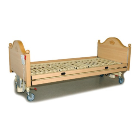
The Princess 5000 lateral tilting bed, is made up of seven major components, comprising of :
Head & Foot boards x 2 (
Due to the weight and size of the components, dismantling should be carried out by two people.
Apply both sets of brakes.
Remove the mattress.
Switch off and remove the plug from the mains outlet.
With the side rails raised, loosen each of the knurled plastic
headed bolts, located at the bottom of each end-post on both
the Head and Footboards ( fig 1.1 ). These bolts should be
loosened just enough to allow the side rail mechanisms to
slide out when released.
Locate the main control box situated below the backrest
section. Note on the cover protecting the connectors, each
connection is numbered. To remove this cover use a flat bladed
screw driver and release the two securing lugs at each end,
then remove the cover ( fig 1.2 ). Unplug the black coiled cable
to the Headboard from the control box numbered 4.
Locate connector box situated below leg section ( fig 1.3 ).
Unplug the black coiled cable from the Foot board. (
connector is usually secured with a cable tie which will need
to be removed ).
Undo and remove the bolts and wing nuts securing the central
spindle at both ends. ( fig 1.4 )
fig 1.4
fig 1.0
), Central Spindle (
fig 1.5
A
), Side rails x 2 (
), Frame bars x 2 (
...\CONTROLBOXPICS 008....
C:\\Do...\P5contolbox 008.jpg
this
K:\\CONTROLBOXPICS 005.jpg
C:\\Do...\P5contolbox 005.jpg
Loosen and remove the large
Wing nut and pull off the bar
( fig 1.5 ).
).
fig 1.1
fig 1.2
fig 1.3
Advertisement
Table of Contents

Related Manuals for Action Assist Princess 5000

Summary of Contents for Action Assist Princess 5000
- Page 1 1.0 The Princess 5000 lateral tilting bed, is made up of seven major components, comprising of : Head & Foot boards x 2 ( ), Central Spindle ( ), Side rails x 2 ( ), Frame bars x 2 ( Due to the weight and size of the components, dismantling should be carried out by two people.
- Page 2 With one person at either end, lift out the central spindle gently to avoid damage to the wood of the head and footboards. The central spindle weighs so ensure correct lifting procedures are followed. Undo and remove the eight bolts (position indicated fig 2.0 ), that connect the frame bars to the head and foot boards with an appropriate Allen key.
Need help?
Do you have a question about the Princess 5000 and is the answer not in the manual?
Questions and answers