Advertisement
Quick Links
Advertisement

Subscribe to Our Youtube Channel
Related Manuals for Muncie OMNI-SYSTEM

Summary of Contents for Muncie OMNI-SYSTEM
- Page 1 OMNI-SYSTEM S N O W & I C E D I V I S I O N OPERATION AND CONFIGURATION MANUAL...
- Page 2 PAGE 1 OMNI-SYSTEM...
- Page 3 TABLE OF CONTENTS Features and Specifications ......................4 Controller Pinnouts ........................5 Operation Screens.........................6 Controller Alerts ..........................7 Accessing Configuration ......................8 Configuration Menu—Software/Passcode Reset ...............9 Configuration Menu—Datalogging Menu ..................10 Configuration Menu—Spreader Settings .................. 11 Configuration Menu —Dump Settings ..................13 Configuration Menu—Plow Settings ..................14 PAGE 2 SNOW &...
- Page 4 PAGE 3 OMNI-SYSTEM...
- Page 5 FEATURES & SPECIFICATIONS Controller Specifications • Voltage Input Range (10VDC—16.5VDC) • Max Operating Current (1.5 Amps) • Open and Short Circuit Protection • CAN Communication Protocol Electrical System Features • Configurable Error Status Indicators • Upgradeable Software • AVL System Ready •...
- Page 6 CAN1 L 120 term CAN1 H +5VOUT 0.5A MAX Detailed enlarged drawing of the Main Controller Connector. J1708 A J1708 B A.10 +VIN A.11 A.12 DIG1 GND Trigger A.13 DIG2 Selectable +/- A.14 DIG3 Selectable +/- or PWM PAGE 5 OMNI-SYSTEM...
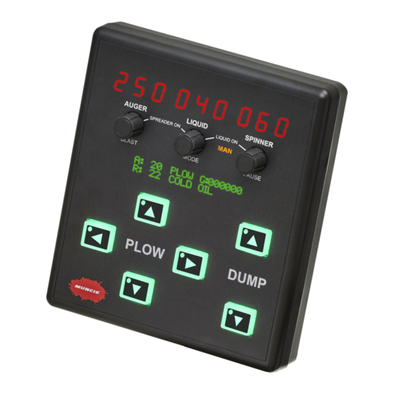
- Page 7 FEATURES AND SPECIFICATIONS ON–OFF CONTROLS: Air/Road Joystick Granular Temperatures Mode Totals Controller on-off: The controller is powered through a keyed ignition switch. Spreader on-off: Depress the auger and liquid knobs to activate the auger and spinner. Rotate the auger and spinner knobs to increase the rates to the desired settings.
- Page 8 Cylinder Buttons ERR will also appear on the alert display in the event a joystick has been disconnected. PAGE 7 OMNI-SYSTEM...
- Page 9 CALIBRATION SCREENS ACCESSING CONFIGURATION MENU: This menu is passcode protected to limit access to non-authorized personnel. It is recommended to change the passcode from the default value to limit access and prevent unintentional system adjustments. Follow the steps below to enter the configuration menu: 1.
- Page 10 FIRMWARE SECONDARY adjustable and reference only. Firmware Liquid Mod: All firmware menus are non- FIRMWARE LIQUID MOD adjustable and reference only. 0.0.0 Passcode Change: Using the liquid and spinner PASSCODE knobs, adjust the default passcode. CHANGE 0001 PAGE 9 OMNI-SYSTEM...
- Page 11 CONFIGURATION MENU DATALOGGING MENU: DATALOGGING Clear System Totals: Depress the spinner knob to CLEAR SYSTEM TOTALS clear the system datalog totals. GLOBAL EQUIPMENT GLOBAL EQUIPMENT SETTINGS: Unloader - Type: Rotate the liquid knob to select the appropriate unloader type. Selections include open (gear pump), closed (piston pump), none (alternate piston pump setup).
- Page 12 This setting is adjustable from 0 - 20 seconds. Turning this setting above 0 will cause the auger to blast material. Use the spinner knob to adjust this setting. PAGE 11 OMNI-SYSTEM...
- Page 13 CONFIGURATION MENU BODY SPREADER BODY SPREADER SETTINGS: Auger Min/Max: The min setting should be adjusted AUGER so that the auger is barely turning. The max setting 013% is the maximum preferred auger speed. Spinner Min/Max: The min setting should be adjusted so that the spinner is barely turning.
- Page 14 The min% allows the 015% 065% deadband to be removed from the joystick operation. The max% controls the cylinder speed when the joystick is fully deflected or using the panel buttons. PAGE 13 OMNI-SYSTEM...
- Page 15 CONFIGURATION MENU PLOW SETTINGS: CYLINDER - PLOW Plow Cyl: This setting determines if the cylinder is a PLOW single acting or double acting design. DOWN 0600 Plow PSI: Adjust this setting to control the downside relief pressure. Keep in mind that the downside relief is disabled when the cylinder is set for single acting.
- Page 16 201 East Jackson Street • Muncie, Indiana 47305 800-367-7867 • Fax 765-284-6991 • info@munciepower.com • www.munciepower.com Specifications are subject to change without notice. Visit www.munciepower.com for warranties and literature. All rights reserved. © Muncie Power Products, Inc. (2018) A Member of the Interpump Group IN20-01 (Rev. 05-20)
Need help?
Do you have a question about the OMNI-SYSTEM and is the answer not in the manual?
Questions and answers