Table of Contents

Related Manuals for Sissel Hang Up

Summary of Contents for Sissel Hang Up
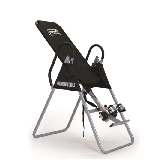
- Page 1 ® SISSEL Hang Up Die hochbelastbare Inversionsbank The extremely robust inversion table Table d’inversion. Qualité et robustesse Tabla inversora muy robusta Gebrauchsanweisung Instructions for use Manuel d’utilisation Manuel de instrucciones...
- Page 2 Dear Customer Thank you for purchasing a SISSEL - inversion table. A good decision for yourself, your health, your fitness and your sense of wellbeing, as well as the prevention of potential ailments. This apparatus enables you to do the exercises necessary to improve your cardiovascular system and strengthen your musculature in the comfort of your own home.
-
Page 3: Safety Instructions
Safety instructions Please read the instructions carefully prior to assembly. Use the device only on an unobstructed, even surface Make sure there is adequate free space to assemble the device. Keep hands and feet away from moving parts during operation Do not place any objects in openings. - Page 4 Consult your doctor or therapist if necessary. However, if you suffer from the following complaints, illnesses or conditions, you should not use the SISSEL - inversion table or use it only after consulting your doctor: Hernia ...
- Page 5 Exploded view Parts overview AG 02 V4 25 / 80...
-
Page 6: Parts List
Parts list Code Description Front U-frame Rear U-frame Adjustable arm Table frame Pivot arm with position openings Adjustable instep frame Steel Heel Holder Bracket Right Folding Arm Left Folding Arm Bars Hex-head screw M8 x 23mm Hex-head screw M6 x 47mm Cross-head screw M6 x 30mm Washers... - Page 7 Parts packing list Code Description Hex-head screw M6 x 47mm Washers Ø20*Ø8.5*1.5 Washer Ø16*Ø6.5*1.0 Hex-head screw M8 x 25mm Hex-head screw M8 x 50mm Square end cap Hex-head screw M8 x 38mm End cap Ø27*Ø13.5 Pivot arm ring Double ended wrench M 12 / M 14 Phillips Screwdriver Note:...
- Page 8 Assembly instructions Back Front Step 1 Stand up the base of the machine by separating the u-frames. Pull the Front and Rear U-Frames (1, 2) as far apart from each others as possible. Then push down on the middle of the Left and Right Folding Arms (8L, 8R) until they are fully locked down.
- Page 9 Step 2 Push the two cover caps (48) onto the nuts (15). Slide the protective covers (37), as shown, on each side of the base and pull them down until the bottom edges of the covers are positioned just below the left and right folding arms (8L, 8R). Close the Velcro(R) strips on the underside of the protective covers (37) so that the covers are fastened to the left and right folding arms (8L, 8R).
- Page 10 Step 3 Slide the lower end of the pivot arm (5) from above into the retainers attached to each side of the table. The axis must be pointing outwards and the table upwards (nameplate on top). Slide each of the pins into one of the three position openings in the pivot arm. The positions must be the same on both sides.
- Page 11 Step 4 Attach the pivot arm rings (49) to the pivot arms (5), see Fig. A + B. Mount the table frame (4) onto the rear U-frame (2) by inserting the ends of the pivot arms (5) into the notch in the plates.
- Page 12 Step 5 Slide the Rod (9) through the large round hole on the side of the Adjustable Boom (3) and secure the Rod (9) on the Adjustable Boom (3) with one M6x47 Hex Head Bolt (11), one M6 Lock Nut (16) and two Ø 16xØ 6.5x1.0 Washers (27). Slide one Steel Heel Holder Bracket (7) and one Rubber Heel Holder (31) onto one end of the Rod (9) until the lock tooth is wedged into the slot in the Rod (9) as shown in small figure.
- Page 13 Step 6 Attach the Adjustable Instep Frame (6) to the Adjustable Boom (3) by inserting the Adjustable Instep Frame (6) into the square bracket on the boom. Slide the Adjustable Instep Frame (6) completely into the square bracket, insert the M6x47 Hex Head Bolt (11) with a Ø16xØ6.5x1.0 Washer (27) halfway through the square bracket, slide the M6x47 Hex Head Bolt (11) through the ring at the bottom of the Spring (23), slide the M6x47 Hex Head Bolt (11) through the rest of the square bracket, and secure at the other end with a Ø16xØ6.5x1.0 Washer (27) and M6 Lock Nut (16).
- Page 14 Step 7 Slide the arm (3), with the scale at the top, into the square tube at the lower end of the table (4). Pull out the large spring button (18) as you do so. Slide the arm upwards until you reach the desired height value. Refer to the scale affixed to the arm.
- Page 15 Fastening the grips Fasten the upper end of the bar grip (29) on the rear U-frame (2) and the pivot arm reinforcement plates (49) using a hex-head screw (38), a counternut (15) and two washers (13). Fasten the lower end of the bar grip (29) on the rear U-frame (2) using a hex-head screw (43), a counternut (15) and two washers (13).
- Page 16 Step 9 Fasten the nylon strap (32 + 33) you have just fitted to the inversion table. Do this by hooking the safety karabiner hooks (19) located on the nylon strap into the eyelets on the table frame and on the cross strut of the front U-frame (1). AG 02 V4 36 / 80...
-
Page 17: Operation And Settings
Operation and settings 1. Shorten 2. Lengthen The strap In the interests of safety, a nylon strap for controlling and limiting the inversion gradient is enclosed. This strap can be set to various lengths, which allows a greater or lesser inversion gradient. - Page 18 Pivot arm with mounting openings The pivot arms are fitted with several mounting openings. These openings are used to set the inversion gradient. To alter the setting, simply tilt the pivot arm upwards until the pin comes out of its opening. Now slide the pivot arm into the position you want next and push the opening back over the pin.
-
Page 19: General Precautions
General precautions 1. Make sure that the bolt on the pivot arm sits properly in the notch of the base frame. It must be located at the very bottom of the notch. 2. A second person should be present when using the device for the first few times. 3. -
Page 20: Recommendations For Use
Recommendations for use 1. Start slowly: Start with an inversion of just 15° to 20°. Remain in this position for as long as you feel OK. Slowly return to the starting position. 2. Progress slowly: Increase the angle only when you feel comfortable doing so. Increase the angle by just a few degrees each time. - Page 21 Dismantling the inversion table First slide the arm (3) back into the frame as far as it will go. Do this by pulling the knob (30) to release the lock. When the rearmost setting has been reached, gently slide the spring button to and fro until it engages in the next position.
Need help?
Do you have a question about the Hang Up and is the answer not in the manual?
Questions and answers