Table of Contents
Advertisement
Quick Links
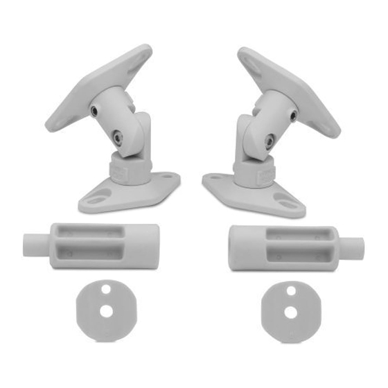
Step 3. Installation of Extension and Link Set
Install 2-1/2" extension portion of speaker mount to wall plate. Secure the allen set screw enough to hold
Extension Mounting
extension in place with the weight of the speaker attached.
Ceiling or Shelf Application Only!
(L)
Do not use
extension in
wall mounted
tighten allen screw using
applications
allen key provided
Install link set portion of speaker mount to wall plate or 2-1/2" extension. Secure the allen set screw enough
tighten allen
Link Set Mounting
to hold assembly in place with the weight of the speaker attached.
(L)
screw using allen
All Applications
key
provided
(L)
Install speaker with speaker post or 2 hole plate attached. Secure the allen set screw enough to
(L)
Speaker Mounting
(L)
hold assembly in place with the weight of the speaker attached. Adjust to desired
angle and secure.
post style speaker
2 hole speaker
plate
plate
Model SATP Satellite Speaker
Mount Assembly Instructions
IMPORTANT CONSIDERATIONS PRIOR TO INSTALLATION
Preview all steps before beginning. Should any portion of these instructions be unclear, contact us at 800-582-9595 for assistance. Do Not Attempt to
install this speaker mount if you have any doubts as to its proper installation. This speaker mount is specifically designed for mounting small surround
style speakers weighing 8 lbs. or less. Use of this speaker mount for any other purpose unless specified by the manufacturer is not recommended.
Before you begin, separate the speaker mount parts by loosening the set screws with the supplied allen wrench and simply twist apart.
Exploded View
Speaker / Wall Plate (4)
2-1/2" Extension (2)
Link Set (2)
(assembled at factory)
Speaker Post (2)
Speaker / Wall Plate (4)
Do not use extensions
in wall mounted
"TOGGLER is a registered trademark of Mechanical Plastics Corp." ALLIGATOR® ANCHOR
"Patented under US Patent numbers 4,181,061; 4,752,170 and 5,161296 and foreign counter-
applications
parts thereof. Other patents pending."
Maximum Speaker Weight: 8 lbs
All Vantage Point Products Corp. products are manufactured to ensure superior quality, performance and durability for a lifetime of use . Warranty covers
the product to be free of defects in materials and workmanship under normal and reasonable use. Vantage Point Products will repair or replace, at our
option, any product which proves to be defective upon our inspection. This warranty will not apply to products that have been lost or damaged by misuse,
abuse or accident, altered or repaired in any way or by any person or fi rm other than specifi ed by us, used in violation of instructions or incorrect assembly
nor used in a manner other than specifi ed by us. This warranty is nontransferable to a new owner and may require proof of purchase. All claims must be
directly handled with Vantage Point Products Corp. by calling us at 1-800-582-9595.
Vantage Point Products Corp • P.O. Box 2485 Santa Fe Springs, CA 90670 USA
USA Tel: 1.800.582.9595 • Canada Tel: 905.607.9994 • Europe Tel: 31.72.581.6056
Web Site: www.vanptc.com • Email: cons-serv@vanptc.com
A - M5 x 20mm machine screw (2)
B - 8-32 x 5/8" machine screw (2)
C - 1/4"-20 x 1/2" machine screw (4)
D - 1/4"-20 x 7/8" machine screw (2)
E - M5 x 1/8" plastic washer (2)
F - 8-32 round key hole nut (2)
G - #8 x 3/4" self tapping screw (2)
H - #12 x 3/4" self tapping screw (4)
I - #12 x 1-3/4" self tapping screw (4)
J - #12-14 TOGGLER® ALLIGATOR
plastic anchor (4)
K - M4 x 8mm flat head
machine screw (2)
L - 5/32" allen wrench (1)
WARRANTY INFORMATION
6i33-08/05
Advertisement
Table of Contents

Related Manuals for Vantage Point Products SATP


Summary of Contents for Vantage Point Products SATP
- Page 1 All Vantage Point Products Corp. products are manufactured to ensure superior quality, performance and durability for a lifetime of use . Warranty covers the product to be free of defects in materials and workmanship under normal and reasonable use. Vantage Point Products will repair or replace, at our option, any product which proves to be defective upon our inspection.
- Page 2 TYPE 6. SPEAKER PLATE 2 or 4 Factory Installed 1/4”-20 Threaded Inserts. Step 1. Installation of Speaker Post or Speaker Plate Find the best mounting configuration that matches your speaker. Four hole speaker mount patterns can be accommodated by positioning the speaker plate diagonally (see Fig. 6) Using the 1/4”-20 x 1/2” machine screws (C) install the speaker plate and Supplied are parts and hardware for mounting to various manufacturers speakers.
Need help?
Do you have a question about the SATP and is the answer not in the manual?
Questions and answers