
Summary of Contents for Diablo Controls, Inc. DSP-55
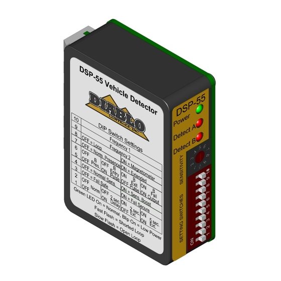
- Page 1 User Manual DSP-55 Vehicle Detector with Two Outputs and Supports the Free Exit Probe Diablo Controls, Inc. Copyright © 2017 Document: DSP55_MAN_D Released: 11/30/2020 Pros Who Know Trust Diablo...
-
Page 2: Table Of Contents
Power LED Shows Two Quick Flashes Once Every Two Seconds................26 Detect LED Intermittently Comes On / Stays On Without a Vehicle Present ............26 Detect LED Will Not Come On With a Vehicle Present ..................27 DSP-55 User Manual Page 2 of 28 DSP55_MAN_D... -
Page 3: Figures
Figure 9: Loop Installation ............................22 Figure 10: Saw Cut for Home Run Exit and Chiseled Corner for Home Run Exit ............. 22 Figure 11 Typical Free exit probe Installation ......................23 DSP-55 User Manual Page 3 of 28 DSP55_MAN_D... -
Page 4: Introduction
The small package is powered by a high-performance 8-bit microcontroller that does not skimp on performance. The DSP-55 detector has a small footprint and was designed to retrofit into many existing locations that may require a detector upgrade. This allows maintenance personnel to carry only one detector to meet most, if not all, of their vehicle detection needs. -
Page 5: Functional Data
140ms ±20ms Vehicle Hold Time: In Normal Presence Mode: Approximately 1 hour for a detection of 1% ΔL/L. In Extended Presence Mode: Approximately 1 to 2 days for a detection of 1% ΔL/L. DSP-55 User Manual Page 5 of 28 DSP55_MAN_D... -
Page 6: Electrical Data
With a call is 40 milliamps maximum. Environmental Data Operating Temperature: -35°F to 165°F (-37°C to 74°C) Storage Temperature: -40°F to 176°F (-40°C to 80°C) Humidity: Up to 95% relative humidity non-condensing DSP-55 User Manual Page 6 of 28 DSP55_MAN_D... -
Page 7: Mechanical Data
Mounting Position: Housing Material: Lexan Housing Size: 2.375 inches (High) x 2.240 inches (Wide) x .860 inches (Deep) 60.33 mm (High) x 56.90 mm (Wide) x 21.84 mm (Deep) Figure 2: Physical Dimensions DSP-55 User Manual Page 7 of 28 DSP55_MAN_D... -
Page 8: Features And Functions
The three outputs that are available on the DSP-55 are Output A, Output B, and Output B Inverted. The operation of Outputs A and B are discussed in the following sections. Output B Inverted is always the opposite of Output B. -
Page 9: Presence Detection
250 milliseconds long. If the 2-second delay feature is active, Output A and Output B will not pulse until a vehicle has been continually detected for the 2-second delay time. DSP-55 User Manual Page 9 of 28 DSP55_MAN_D... -
Page 10: Sensitivity (Rotary Switch)
The factory default is five (5). Like most inductive loop vehicle detectors, the DSP-55 directly measures the change in frequency of the loop and from there, calculates the change in inductance when a vehicle interacts with it. The change in inductance is measured as %ΔL/L (reads as “percent delta L over L”). -
Page 11: Loop / Magnetometer (Dip Switch 8)
Factory Default Loop / Magnetometer (DIP Switch 8) The DSP-55 is capable of operating with either a standard inductive loop or the new mini-loop (magnetometer). As usual, the inductive loop operates in both presence and pulse modes. However, the mini-loop (magnetometer) can only operate in pulse mode and will automatically override any settings to the contrary. -
Page 12: Output B Selection (Dip Switches 5 And 6)
Output B. If extension time is selected, the pulse will occur after the extension time has completed. Fail: If the DSP-55 recognizes some type of loop failure, Output B will be activated. Output B will remain activated until the failure is corrected. -
Page 13: Figure 3: Outputs With No Delay Or Extension
Figure 3: Outputs with No Delay or Extension Figure 4: Outputs with Delay Figure 5: Outputs with Extension DSP-55 User Manual Page 13 of 28 DSP55_MAN_D... -
Page 14: Normal Sensitivity / Sensitivity Boost (Dip Switch 4)
Fail-Safe / Fail-Secure (DIP Switch 3) On the DSP-55, the option for fail-safe or fail-secure only applies to Output A. In general, a fail-safe detector will activate the output when the loop circuit is failed. This is useful on a safety loop to prevent accidental closure of a gate on a vehicle. -
Page 15: Delay / Extension (Dip Switches 1 And 2)
Delay and extension cannot be selected at the same time. The possible delay and extension settings are summarized in the table below: DIP Switch Output A Output A Delay Time Extension Time None None 2 seconds None None 2 seconds None 5 seconds Factory Default DSP-55 User Manual Page 15 of 28 DSP55_MAN_D... -
Page 16: Indicators
Indicators The DSP-55 is equipped with three (3) LED indicators: Power (Green), Detect A (Red), and Detect B (Red). Power LED – The green power LED indicates these possible states: The voltage applied to the detector is less than the minimum display voltage of approximately 5 volts. -
Page 17: Figure 6: Power Led States
LED will turn off for 500 milliseconds, on for 500 milliseconds, blink repeatedly with 50 milliseconds on followed by 50 milliseconds off for one second, and then display its normal state. Output A will be deactivated during this time. DSP-55 User Manual Page 17 of 28 DSP55_MAN_D... -
Page 18: Figure 7: Detect A Led States
Detect B LED – The red Detect B LED is used to display the status of Output B. There are several different statuses that can be displayed on this LED: No vehicle present in the detection area or the detector has identified a fault and has deactivated Output B. DSP-55 User Manual Page 18 of 28 DSP55_MAN_D... -
Page 19: Figure 8: Detect B Led States
A vehicle is detected and Output B is activated or the detector has identified a fault and has activated Output B because it is in the fail output mode of operation. Figure 8: Detect B LED States DSP-55 User Manual Page 19 of 28 DSP55_MAN_D... -
Page 20: Installation
Wiring: If plugging the detector in to the operator, you should be certain that the operator pin out for its connector is the same as that of the DSP-55 detector and that the voltage supplied to the detector is between 10 and 30 volts DC. - Page 21 This will also help remove dust from the saw cutting operation from the sides of the saw slot. This will allow better adhesion of the loop sealant to the saw slot. DSP-55 User Manual Page 21 of 28...
-
Page 22: Figure 9: Loop Installation
BACKER ROD PIECE LOOP WIRE CUTS DETAIL B DETAIL A Figure 9: Loop Installation Figure 10: Saw Cut for Home Run Exit and Chiseled Corner for Home Run Exit DSP-55 User Manual Page 22 of 28 DSP55_MAN_D... -
Page 23: Free Exit Probe Installation
Once the loop wire leaves the saw slot it should be twisted at least three times per foot. More is better. The twists should be kept tight to be most effective in reducing the effects of electrical interference. Free Exit Probe Installation Figure 11 Typical Mini-Loop Installation DSP-55 User Manual Page 23 of 28 DSP55_MAN_D... -
Page 24: Configuration
First is to add a second Free exit probe to the opposing side of the roadway. The probes must be wired in series. The second is to use the DSP-55 Free Exit Probe kit. The DSP-55 can be used with a loop detector or with our Free Exit Probe. -
Page 25: Troubleshooting
The LED should begin flashing at a much slower rate (½ second on, ½ second off). If it does not change its flashing rate, change the detector. DSP-55 User Manual Page 25 of 28 DSP55_MAN_D... -
Page 26: Power Led Shows Two Quick Flashes Once Every Two Seconds
DSP-55 User Manual Page 26 of 28... -
Page 27: Detect Led Will Not Come On With A Vehicle Present
5 is the correct setting. However, to compensate for some unusual loop geometries, this setting may be inadequate. Adjust the sensitivity one level higher and recheck the detector for proper detection. DSP-55 User Manual Page 27 of 28... - Page 28 If the problem follows the loop the loop is the problem. If it stays in the same detector, replace the detector. DSP-55 User Manual Page 28 of 28...
Need help?
Do you have a question about the DSP-55 and is the answer not in the manual?
Questions and answers