Table of Contents
Advertisement
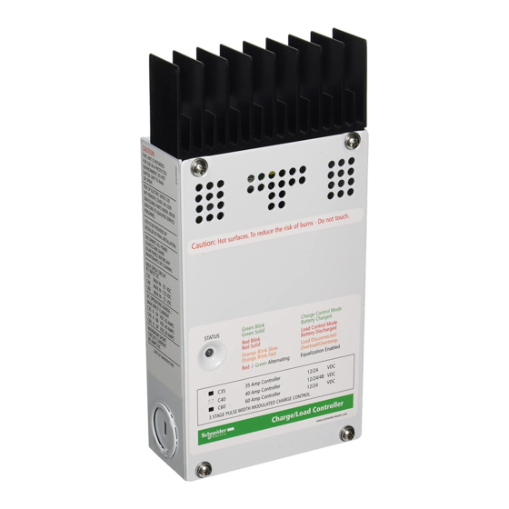
Introducing the C40
Introducing the C40
The C40 controller is the finest large-system
controller available. The C40 can be used with
12, 24, or 48-volt DC systems as a PV charge
controller, a DC diversion controller, or a DC
load controller (low voltage disconnect). These
capabilities make the C40 the only DC controller
you'll need! Numerous standard features are
provided to maximize the performance of the
system:
!
Silent, solid-state Pulse Width Modulated
(PWM) charging process with three-stage
control, temperature compensation, and
manual or automatic equalization.
Maximizes system performance and
increases battery life.
!
Meets National Electrical Code (NEC) and
other international controller specifications.
!
Certified by ETL for the U.S. (UL Standard
1741 (draft), and Canada (CSA-C22.2 No.
14-M91 SEP 91)
!
Electronic overload and short circuit
protection with automatic and manual reset
capability increases the reliability of
unattended systems by eliminating blown
fuses and tripped circuit breakers
!
Field adjustment of charge setpoints is
provided by rotary controls with removable
knobs, reducing the potential for setpoint
tampering. Calibrated scales and test points
allow precise adjustments of settings
!
Optional external battery temperature compensation sensor (BTS) for automatic
adjustment of charge setpoints (required by UL draft standard 1741 and strongly
recommended for sealed batteries)
!
Over-temperature protection of the electronic circuitry (by reducing the charge rate)
improves the reliability of the C40 when used in environments over 113 F / 45 C.
!
Indoor-type, powder-coated enclosure for wall mounting
!
Multi-color status LED with matching color label for mode/status indication
!
Optional LCD meter for remote or direct mounting on the C40. May be mounted up to
1000 feet away
!
2 year limited warranty
©
Copyright
Trace Engineering Co. Inc.
th
5916 195 Street, NE
Arlington, WA 98223 USA
C 4 0
Charge-Diversion
& Load Controller
Tel (360) 435-8826
Fax (360) 435-2229
www.traceengineering.com
°
°
Part Number 2680 Rev. C
November 4, 1998
1
Page
Advertisement
Table of Contents

Related Manuals for Trace Engineering C40

Summary of Contents for Trace Engineering C40
- Page 1 Over-temperature protection of the electronic circuitry (by reducing the charge rate) ° ° improves the reliability of the C40 when used in environments over 113 F / 45 C. Indoor-type, powder-coated enclosure for wall mounting Multi-color status LED with matching color label for mode/status indication Optional LCD meter for remote or direct mounting on the C40.
-
Page 2: Important Safety Instructions
Do not attempt to repair the C40. Take it to a qualified service center when service or repair is required. Incorrect re-assembly may result in a risk of electric shock or fire. -
Page 3: Personal Precautions
A single battery can produce a short- circuit current high enough to weld a ring to a battery terminal, causing severe burns. Other Products from Trace Engineering: MicroSine miniture utility-interactive inverter fits on back of 24-volt PV solar module. -
Page 4: Operating Modes
DC load controller. The C40 cannot operate as both a charge controller and a DC load controller at the same time. If both are required in a system, two C40’s must be installed. Use one C40 for each mode desired. -
Page 5: Battery Controller
Diversion loads in excess of 63 amps are capable of absorbing more power than the C40 is designed to handle, resulting in an over-current shut down. During this time, the unit will not regulate electrical flow in the system, and battery damage may result. -
Page 6: Over Temperature Protection
C40. The BTS is required by UL Standard 1741(draft). ETL approval is based on its installation. However, do not install the battery temperature sensor if you are using the C40 as a DC load controller. The BTS may be extended by using a standard phone cable with RJ-11 plugs. -
Page 7: Led Status Indicator
A multi-color LED indicator is provided to indicate the operating status of the C40. A color-coded label is included on the cover of the C40 to explain the status LED’s operation. When the C40 is in Charge Control or Load Diversion mode, the LED will be green. -
Page 8: Equalization Mode Indication
The C40 will try to automatically restart the loads after a 10 minute delay. If the C40 will not restart, turn off all loads and press the reset switch. If the C40 then restarts, the loads may be too large. A delay up to five seconds may occur before the C40 attempts to restart after pressing the reset switch. - Page 9 The minimum recommended wire gauge is 8 AWG (13.3 mm2) with a 75° C insulation rating. The terminals on the C40 will accept up to #2 AWG (33.6mm2) copper or aluminum wire. No crimp-on terminals or lugs are required. The following table gives the maximum permissible length allowed for each wire size at 40 amps with 3% voltage drop.
- Page 10 (feet/meters) to the C40 (or the distance from the C40 to your load) on the same line, then read the wire size required at the top of the column. Don’t use wire smaller than #8 gauge.
- Page 11 50VDC for a 24-volt system, and 25VDC for a 12-volt system. If the optional digital volt meter (DVM/C40 or C40R) is attached to the C40, be sure to set the jumper on the back of it for the appropriate system voltage. The jumper for limiting power consumption and dimming the DVM display is also located on the back of the DVM.
- Page 12 In Charge Control mode or Diversion Control mode, you can adjust the Bulk and Float charging voltage by adjusting the potentiometers (pots) located in the bottom center of the C40 circuit board (for more information regarding Bulk and Float settings, see the Three Stage Battery Charging Process section of this manual).
-
Page 13: Manual Equalization
If you are using the C40 as a DC load controller, be sure to set the pots as shown in the Load Control section of this manual. The upper knobs settings are reduced by one volt, resulting in a range of 14.0 to 12.0 VDC (for a 12 volt system). The lower knobs settings are reduced by two volts, resulting a range of 12.5 to 10.5 VDC (for a 12 volt system). -
Page 14: Temperature Compensation
Multiple “grace” periods are allowed, but the duration of the ‘grace’ period will vary with battery voltage. The EQUALIZE jumper allows the C40 to be set for AUTO reconnect of the DC load when the voltage exceeds the LVR setting. - Page 15 Totalizing amp-hours: 0 to 65536 ah; resets to zero when power is disconnected Status LED: green, red, or orange If the C40 is disconnected from the battery or the DVM cable, the DVM will be reset when it is powered up.
-
Page 16: Three Stage Battery Charging
The unit can also be surface mounted with relief behind it, and it can be located up to 1000 feet from the C40 itself. If the DVM meters appear inaccurate or unusual on runs over 100 feet from the C40, remove the jumper located below the voltage configuration pins on the back of the C40R. - Page 17 DC loads may need to be disconnected by turning off circuit breakers or removing fuses before equalization to prevent damage by the required higher voltages. © Copyright Trace Engineering Co. Inc. Tel (360) 435-8826 Part Number 2680 Rev. C 5916 195 Street, NE...
-
Page 18: Automotive Batteries
Batteries come in different sizes, types, amp hour capacity, voltages and chemistries. Here are a few guidelines that will help in battery selection, and ensure that the batteries are properly maintained. The best source of the most appropriate settings for the C40 will be from the manufacturer or supplier of the batteries. -
Page 19: Nicad And Nife Batteries
To use the C40 with NiCad batteries, remove the resistor labeled “R46” in the middle of the C40 circuit board by cutting it. This adds two volts to the printed scale on the circuit board around the BULK and FLOAT potentiometers. When NiCad mode is selected, the equalization process is disabled. - Page 20 80% of the diversion load controller’s current handling ability. For example, if a Trace C40, 40 amp diversion load controller is being used, do not place a combination of charging sources which are capable of putting out more than 32 amps (80% of 40 amps) on the load controller’s circuit.
-
Page 21: Warranty Procedure
WarrantyProcedure Complete the warranty card and mailed it to Trace Engineering within ten (10) days from the date of purchase. Keep your bill of sale as proof of purchase, should any difficulties arise concerning the registration of the warranty card. -
Page 22: Limited 2 Year Warranty
Trace does not warrant its products from any and all defects: (1) arising out of material or workmanship not provided by Trace Engineering, or (2) resulting from abnormal use of the product or use in violation of the instructions, or (3) in products repaired... - Page 23 © Copyright Trace Engineering Co. Inc. Tel (360) 435-8826 Part Number 2680 Rev. C 5916 195 Street, NE Fax (360) 435-2229 November 4, 1998 Arlington, WA 98223 USA www.traceengineering.com Page...
- Page 24 © Copyright Trace Engineering Co. Inc. Tel (360) 435-8826 Part Number 2680 Rev. C 5916 195 Street, NE Fax (360) 435-2229 November 4, 1998 Arlington, WA 98223 USA www.traceengineering.com Page...
Need help?
Do you have a question about the C40 and is the answer not in the manual?
Questions and answers