Table of Contents
Advertisement
Quick Links
Advertisement
Chapters
Table of Contents

Summary of Contents for Spectra Verde Series
- Page 1 Spectra Verde Array User Guide SpectraLogic.com...
- Page 2 History Revision Date Description February 2015 Update for Verde 2.1 release. September 2015 Update for Verde 2.2 release. November 2015 Additional updates for Verde 2.2 release. March 2016 Update for Verde 3.1 release. April 2016 Update for Verde 3.1.1 release. May 2016 Update for Verde 3.1.2 release. June 2016 Update for Verde 3.1.3 release. Never Released. December 2016 Update for Verde 3.1.4 release. April 2017 Update for Verde 3.5.0 release. September 2017 Update for Verde 4.0 release. To make sure you have the most current version of this guide check the Note: Spectra Logic Technical Support portal at support.spectralogic.com/documentation/user‐guides/. To make sure you have the release notes for the most current version of the Verde Release Notes, check the Spectra Logic Technical Support portal at support.spectralogic.com/documentation/release‐notes/. You must sign into the portal before viewing Release Notes. The release notes contain updates to the User Guide since the last time it was revised. September 2017 User Guide—Spectra Verde Array...
- Page 3 Software Product. 3. GENERAL The Software Product is licensed, not sold, to you by Spectra for use only under the terms of this EULA. The Software Product is protected by copyright laws and international copyright treaties, as well as other intellectual property laws and treaties. The rights granted herein are limited to Spectraʹs and its licensorsʹ intellectual property rights in the Software Product and do not include any other patents or intellectual property rights. The terms of this EULA will govern any software upgrades provided by Spectra that replace and/or supplement the original Software Product, unless such upgrade is accompanied by a separate license in which case the terms of that license will govern. 4. SOFTWARE PRODUCT The Software Product, as used in this EULA, means, collectively and/or as applicable: The Software Product package; Any and all contents, components, attachments, software, media, and code with which this Agreement is provided and delivered; Any and all images, photographs, art, art work, clip art, fonts or other artistic works (the ʺArt Workʺ); Related explanatory written materials and instructions, and any other possible documentation related thereto (ʺDocumentationʺ); and Upgrades, modified versions, updates, additions and copies of the Software Product (the ʺUpgradesʺ), if any, licensed to by Spectra under this EULA. September 2017 User Guide—Spectra Verde Array...
- Page 4 6. DESCRIPTION OF OTHER RIGHTS AND LIMITATIONS A. Spectra will provide you with support services related to the Software Product (ʺSupportʺ). Such Support will be provided in accordance with the Spectra Master Support Agreement, available for download and viewing on the Spectra Corporate Web site. Use of Support is governed by this EULA and Spectraʹs Master Support Agreement, B. Any supplemental software, code, content, or media provided to you in the course of Support shall be considered part of the Software Product and subject to the terms and conditions of this EULA. C. Spectra retains all right, title, and interest in and to the Software Product, and any rights not granted to you herein are reserved by Spectra. You hereby expressly agree not to extract information, reverse engineer, disassemble, decompile, or translate the Software Product, or otherwise attempt to derive the source code of the Software, except to the extent allowed under any applicable law. In the event that such activities are permitted by applicable law, any information you, or your authorized agent, discover shall be promptly disclosed to Spectra and shall be deemed the confidential information of Spectra. D. You shall not modify, sublicense, assign, or transfer the Software Product or any rights under this EULA, except as expressly provided in this EULA. Any attempt to other sublicense, assign, or transfer any of the rights, duties, or obligations will be void. E. You may permanently transfer all of your rights under this EULA, provided you retain no copies. The other party must agree to accept the terms and conditions of the EULA. 7. ALL RESERVED All rights not expressly granted herein are reserved by Spectra. September 2017 User Guide—Spectra Verde Array...
- Page 5 A. Spectra shall retain all right, title, and interest in the Software Product and to any modifications or improvements made thereto, and any upgrades, updates or Documentation provided to End User. End User will not obtain any rights in the Software Product, its updates, upgrades, and Documentation, as a result of its responsibilities hereunder. B. B. End User acknowledges Spectraʹs exclusive rights in the Software Product and that the Software Product is unique and original to Spectra and that Spectra is owner thereof. Unless otherwise permitted by law, End User shall not, at any time during or after the effective Term of the Agreement, dispute or contest, directly or indirectly, Spectraʹs exclusive right and title to the Software Product or the validity thereof. 10. U.S. GOVERNMENT END USERS The Software Product and related documentation are ʺCommercial Items,ʺ as that term is defined at 48 C.F.R. §2.101, consisting of ʺCommercial Computer Softwareʺ and ʺCommercial Computer Software Documentation,ʺ as such terms are used in 48 C.F.R. §12.212 or 48 C.F.R. §§227.7202‐1 through 227.7202‐4, as applicable. The Commercial Computer Software and Commercial Computer Software Documentation are being licensed to U.S. Government end users (a) only as Commercial Items and (b) with only those rights as are granted to all other End Users pursuant to the terms and conditions herein. Unpublished rights reserved under the copyright laws of the United States. 11. EXPORT LAW ASSURANCES You may not use or otherwise export or re‐export the Software Product except as authorized by United States law and the laws of the jurisdiction in which the Software Product was obtained. In particular, but without limitation, the Software Product may not be exported or re‐exported (a) into (or to a nation or resident of) any U.S. embargoed countries or (b) to anyone on the U.S. Treasury Departmentʹs list of Specially Designated Nationals or the U.S. Department of Commerce Denied Personʹs List or Entity List. By installing or using any component of the Software Product, you represent and warrant that you are not located in, under control of, or a national or resident of any such country or on any such list. September 2017 User Guide—Spectra Verde Array...
- Page 6 INFORMATION OR ADVICE GIVEN BY SPECTRA OR A SPECTRA AUTHORIZED REPRESENTATIVE SHALL CREATE A WARRANTY. SOME JURISDICTIONS DO NOT ALLOW THE EXCLUSION OF IMPLIED WARRANTIES OR LIMITATION ON APPLICABLE STATUTORY RIGHTS OF A CONSUMER, SO THE ABOVE EXCLUSION AND LIMITATIONS MAY NOT APPLY TO YOU. 13. LIMITATION OF LIABILITY TO THE MAXIMUM EXTENT PERMITTED BY APPLICABLE LAW, IN NO EVENT SHALL SPECTRA, ITS AFFILIATES OR LICENSEES, BE LIABLE FOR ANY SPECIAL, INCIDENTAL, INDIRECT, OR CONSEQUENTIAL DAMAGES WHATSOEVER (INCLUDING, WITHOUT LIMITATION, DAMAGES FOR LOSS OF BUSINESS PROFITS, BUSINESS INTERRUPTION, LOSS OF BUSINESS INFORMATION, OR ANY OTHER PECUNIARY LOSS) ARISING OUT OF THE USE OF OR INABILITY TO USE THE SOFTWARE PRODUCT OR THE PROVISION OF OR FAILURE TO PROVIDE SUPPORT SERVICES, EVEN IF SPECTRA HAS BEEN ADVISED OF THE POSSIBILITY OF SUCH DAMAGES. IN ANY CASE, SPECTRAʹS ENTIRE LIABILITY UNDER ANY PROVISION OF THIS EULA SHALL BE LIMITED TO THE AMOUNT ACTUALLY PAID BY YOU FOR THE SOFTWARE PRODUCT; PROVIDED HOWEVER, IF YOU HAVE ENTERED INTO A MASTER SUPPORT AGREEMENT, SPECTRAʹS ENTIRE LIABILITY REGARDING SUPPORT SERVICES SHALL BE GOVERNED BY THE TERMS OF THAT AGREEMENT. BECAUSE SOME STATES AND JURISDICTIONS DO NOT ALLOW THE EXCLUSION OR LIMITATION OF LIABILITY, THE ABOVE LIMITATION MAY NOT APPLY TO YOU. 14. CONTROLLING LAW AND SEVERABILITY This EULA will be governed by and construed in accordance with the laws of the State of Colorado, as applied to agreements entered into and to be performed entirely within Colorado between Colorado residents. This EULA shall not be governed by the United Nations Convention on Contracts for the International Sale of Goods, the application of which is expressly excluded. If for any reason a court of competent jurisdiction finds any provision, or portion thereof, to be unenforceable, the remainder of this EULA shall continue in full force and effect. September 2017 User Guide—Spectra Verde Array...
- Page 7 Boulder, CO 80301 Bracknell Berks, RG12 8PE United Kingdom Phone: 1.800.833.1132 or 1.303.449.6400 International: 1.303.449.6400 Phone: 44 (0) 870.112.2150 Fax: 1.303.939.8844 Fax: 44 (0) 870.112.2175 Spectra Logic Technical Support Technical Support Portal: support.spectralogic.com United States and Canada Europe, Middle East, Africa Phone: Phone: 44 (0) 870.112.2185 Toll free US and Canada: 1.800.227.4637 Deutsch Sprechende Kunden Phone: 49 (0) 6028.9796.507 International: 1.303.449.0160...
-
Page 8: Table Of Contents
Contents About This Guide A . . . . . . . . . . . . . . . . . . . . . . . . . . . . . . . . . . NTENDED UDIENCE U I S . . . . . . . . . . . . . . . . . . . . . . . . ERDE NTERFACE CREENS I . . . . . . . . . . . . . . . . . . . . . . . . . . . . . . . . ELATED NFORMATION Typographical Conventions . . . . . . . . . . . . . . . . . . . . . . . . . . . . . . . . . 17 Related Publications . . . . . . . . . . . . . . . . . . . . . . . . . . . . . . . . . . . . . . . . 17 Chapter 1 – Product Overview . . . . . . . . . . . . . . . . . . . . . . . . . . . . . . . . . . . . . . . . . . . VERVIEW . . . . . . . . . . . . . . . . . . . . . . . . . . . . . . . . . . . . . . . . . . . EATURES . . . . . . . . . . . . . . . . . . . . . . . . . . . . . . . . . . . . . . . . OMPONENTS Front View of Master Nodes . . . . . . . . . . . . . . . . . . . . . . . . . . . . . . . . . 22 Rear View of Master Nodes . . . . . . . . . . . . . . . . . . . . . . . . . . . . . . . . . . ... - Page 9 Configure Folders for Replication . . . . . . . . . . . . . . . . . . . . . . . . . . . . 66 Chapter 4 – Managing Network Attached Storage S P . . . . . . . . . . . . . . . . . . . . . . . . . . . ANAGING TORAGE OOLS Expand a Storage Pool . . . . . . . . . . . . . . . . . . . . . . . . . . . . . . . . . . . . . . 70 Delete a Storage Pool . . . . . . . . . . . . . . . . . . . . . . . . . . . . . . . . . . . . . . . 71 V . . . . . . . . . . . . . . . . . . . . . . . . . . . . . . . . . ANAGING OLUMES Move a Volume . . . . . . . . . . . . . . . . . . . . . . . . . . . . . . . . . . . . . . . . . . . . 72 Edit a Volume . . . . . . . . . . . . . . . . . . . . . . . . . . . . . . . . . . . . . . . . . . . . . 72 Delete a Volume . . . . . . . . . . . . . . . . . . . . . . . . . . . . . . . . . . . . . . . . . . . 74 September 2017 User Guide—Spectra Verde Array...
- Page 10 . . . . . . . . . . . . . . . . . . . . . ONFIGURE ETWORKING ERVICES Configure the Active Directory Service . . . . . . . . . . . . . . . . . . . . . . . . 97 Configure the SNMP Service . . . . . . . . . . . . . . . . . . . . . . . . . . . . . . . . . 98 U . . . . . . . . . . . . . . . . . . . . . . . . . . . . . . . . . . . ONFIGURE SERS Description of User Types . . . . . . . . . . . . . . . . . . . . . . . . . . . . . . . . . . 100 Create a User . . . . . . . . . . . . . . . . . . . . . . . . . . . . . . . . . . . . . . . . . . . . . 100 Edit a User . . . . . . . . . . . . . . . . . . . . . . . . . . . . . . . . . . . . . . . . . . . . . . . 100 Delete a User . . . . . . . . . . . . . . . . . . . . . . . . . . . . . . . . . . . . . . . . . . . . . 101 C . . . . . . . . . . . . . . . . . . . . . . . . . . . . . ONFIGURE ERTIFICATES E A K . . . . . . . . . . . . . . . . . . . ANUALLY NTER CTIVATION September 2017 User Guide—Spectra Verde Array...
- Page 11 . . . . . . . . . . . . . . . . . . . . . . . . . . . . . . . . . . . . . . . . . . . Configure a Log Set Schedule . . . . . . . . . . . . . . . . . . . . . . . . . . . . . . . 126 Manually Generate Log Sets . . . . . . . . . . . . . . . . . . . . . . . . . . . . . . . . 127 Email a Log Set . . . . . . . . . . . . . . . . . . . . . . . . . . . . . . . . . . . . . . . . . . . 127 Download a Log Set . . . . . . . . . . . . . . . . . . . . . . . . . . . . . . . . . . . . . . . 128 Delete a Log Set . . . . . . . . . . . . . . . . . . . . . . . . . . . . . . . . . . . . . . . . . . . 128 Chapter 8 – Maintaining a Verde Array I V . . . . . . . . . . . . . . . . . . . . . . . . NTEGRITY ERIFICATION RSC B . . . . . . . . . . . . . . . . . . . . . . . . . . . . . . . . NITIATE ACKUP . . . . . . . . . . . . . . . . . . . . . . . . . . . . . . . . . . . . . . . OMPRESSION September 2017 User Guide—Spectra Verde Array...
- Page 12 Appendix A – Network File Interface . . . . . . . . . . . . . . . . . . . . . . . . . . . . . . . . . . . . . . . . . . VERVIEW . . . . . . . . . . . . . . . . . . . . . . . . . . . . . . . . . . . . . . EQUIREMENTS T R N ‐B JECTING APES LACK EARL . . . . . . . . . . . . . . . . . . . . . . . . . . . . . . . . . . . . NVIRONMENT B S V . . . . . . ONFIGURE LACK EARL YSTEM ERSIONING September 2017 User Guide—Spectra Verde Array...
- Page 13 Create a Storage Pool . . . . . . . . . . . . . . . . . . . . . . . . . . . . . . . . . . . . . . 193 Power on the Secondary Master Node . . . . . . . . . . . . . . . . . . . . . . . 194 Verify the HotPair Configuration . . . . . . . . . . . . . . . . . . . . . . . . . . . . 194 S . . . . . . . . . . . . . . . . . . . . . . . . . . . . . . . . . . . . . . . . . TEPS Appendix C – Specifications S S . . . . . . . . . . . . . . . . . . . . . . . . TORAGE PECIFICATIONS Verde 2U and 4U Master Nodes . . . . . . . . . . . . . . . . . . . . . . . . . . 199 Verde Enterprise Expansion Node . . . . . . . . . . . . . . . . . . . . . . . . . 199 Verde Archive Expansion Node . . . . . . . . . . . . . . . . . . . . . . . . . . . 199 . . . . . . . . . . . . . . . . . . . . . . . . . . . . . . . . . . . . . . . . . . APACITY September 2017 User Guide—Spectra Verde Array...
- Page 14 System Specification . . . . . . . . . . . . . . . . . . . . . . . . . . . . . . . . . . . . . . . 214 Interface Specifications . . . . . . . . . . . . . . . . . . . . . . . . . . . . . . . . . . . . . 215 Interface Connectors . . . . . . . . . . . . . . . . . . . . . . . . . . . . . . . . . . . . . . . 215 Network Interface Cables . . . . . . . . . . . . . . . . . . . . . . . . . . . . . . . . . . 216 Appendix E – Regulatory & Safety Standards EU D C . . . . . . . . . . . . . . . . . . . . . ECLARATION ONFORMITY Certifications . . . . . . . . . . . . . . . . . . . . . . . . . . . . . . . . . . . . . . . . . . . . . 218 CE M . . . . . . . . . . . . . . . . . . . . . . . . . . . . . . . . . . . . . . . ARKING FCC N . . . . . . . . . . . . . . . . . . . . . . . . . . . . . . . . . . . . . . . . OTICE September 2017 User Guide—Spectra Verde Array...
- Page 15 OLICY Appendix F – Open Source Code Acknowledgements & Package List . . . . . . . . . . . . . . . . . . . . . . . . . . . . . . . . . . . . . . . . . . . . PACHE BSD . . . . . . . . . . . . . . . . . . . . . . . . . . . . . . . . . . . . . . . . . . . . . . . . . . . . . . . . . . . . . . . . . . . . . . . . . . . . . . . . . . . . . . . . . . . . . . . . . . . . . . . . . . . . . . . . . . . . . . . . . . . . . . . . . . . . . IKEWISE . . . . . . . . . . . . . . . . . . . . . . . . . . . . . . . . . . . . . . . . . . . . . GINX . . . . . . . . . . . . . . . . . . . . . . . . . . . . . . . . . . . . . . . . . . . . . . R . . . . . . . . . . . . . . . . . . . . . . . . . . . . . . . . . . . . . . AILS ZFS . . . . . . . . . . . . . . . . . . . . . . . . . . . . . . . . . . . . . . . . . . . . . . . P . . . . . . . . . . . . . . . . . . . . . . . . . . . . . . . . NCLUDED ACKAGES September 2017 User Guide—Spectra Verde Array...
-
Page 16: About This Guide
About This Guide ® This guide describes how to configure, monitor, and maintain Spectra ® Verde master nodes, which are referred to as the master node or the array in these instructions. Unless otherwise noted, the instructions in this guide apply to all configurations of the Verde array. This guide also describes how to use the Spectra Verde Enterprise expansion node, and the Verde Archive expansion node. The expansion nodes are used with a master node and cannot be used as a stand‐alone product. When instructions in this guide apply to both the Verde master node and expansion nodes, Verde array, the array, or these arrays are used to refer to both. This guide also describes how to use the Spectra Network File Interface, which is based on the Verde hardware platform. NTENDED UDIENCE This guide is intended for data center administrators and operators who maintain and operate file storage systems. The information in this guide assumes a familiarity with computing terminology, RAID technology, SAS connectivity, and Ethernet networking. You also need to be familiar with installing, configuring, and using data file storage and archival software. ERDE NTERFACE CREENS The Verde user interface changes as new features are added or other modifications are made. Therefore, the screens you see in the Verde user interface may differ from those shown in this guide. ELATED NFORMATION This section contains information about this document and other documents related to the Spectra Verde arrays. -
Page 17: Typographical Conventions
Informationen, die Sie kennen müssen, um Personenschäden zu vermeiden. This guide uses an arrow (>) to describe a series of menu selections. For example: Select Configuration > Network. — means — Select Configuration, then select Network. Related Publications The following documents related to the Spectra Verde arrays are available on the Support Portal website at support.spectralogic.com, and from the Documentation screen on the Verde user interface. The Spectra Verde Array Network Setup Tips provide helpful instructions for troubleshooting common connectivity problems. The Spectra Verde Array Quick Start Guide provides basic instructions for the essential installation and configuration steps. The Spectra Verde Array Command Line Interface Guide describes how to configure, monitor, and maintain the Spectra Verde arrays through the command line interface. The Spectra Verde Array Site Preparation Guide provides important information that you should know before installing a Verde array in your storage environment. The Spectra Verde Array Installation Guide provides instructions for installing a Verde array. September 2017 User Guide—Spectra Verde Array... - Page 18 The Spectra 12‐ & 36‐Drive Chassis Boot Drive Replacement Guide provides instructions for replacing a failed boot drive in the array. The Spectra 12‐, 36‐ & 45‐Drive Chassis Drive Replacement Guide provides instructions for replacing a failed data drive after the array is installed. The Spectra 12‐, 36‐ & 45‐Drive Chassis Fan Replacement Guide provides instructions for replacing a failed fan in the array. The Spectra 12‐, 36‐ & 45‐Drive Chassis Power Supply Replacement Guide provides instructions for replacing a failed power supply after the array is installed. The Spectra 12‐Drive Chassis HBA Replacement Guide and Spectra 36‐Drive Chassis HBA Replacement Guide provide instructions for replacing a failed HBA in the array. The Spectra 96‐Drive Chassis Drive Replacement Guide provides instructions for replacing a failed data drive in the Verde archive expansion node. The Spectra 96‐Drive Chassis Fan Replacement Guide provides instructions for replacing a failed fan in the archive expansion node. The Spectra 96‐Drive Chassis Power Supply Replacement Guide provides instructions for replacing a failed power supply in the archive expansion node. The Spectra 96‐Drive Chassis I/O Module Replacement Guide provides instructions for replacing a failed I/O module in the archive expansion node. September 2017 User Guide—Spectra Verde Array...
-
Page 19: Chapter 1 - Product Overview
HAPTER Product Overview This chapter provides an overview of the Spectra Verde arrays’ features and components. Topic Overview page 20 Features page 20 Components page 22 Front View of Master Nodes page 22 Rear View of Master Nodes page 24 Rear Panel of Master Nodes page 26 Front View of the Verde Enterprise Expansion Node page 28 Rear View of the Verde Enterprise Expansion Node page 29 Front View of the Verde Archive Expansion Node page 30 Rear View of the Verde Archive Expansion Node page 31 Software page 32 Operating System page 32 Logical Volume Manager and File System... -
Page 20: Overview
Expansion Nodes The Verde enterprise expansion node accommodates up to 44 disk drives with an active bezel, and 45 disk drives with a passive bezel, and can be connected to a master node to increase overall capacity of the array. The Verde archive expansion node holds up to 96 disk drives. HotPair Two Verde master nodes can be connected to multiple expansion nodes in a failover configuration. One master node acts as the primary controller, and the other acts as the secondary. In the event that the secondary controller detects a failure of the primary controller, it automatically takes over to provide uninterrupted operation, without administrative intervention. File Sharing Connectivity for Major Operating Systems The Network File System (NFS) and Common Internet File System (CIFS) protocols provide connectivity to most major operating systems, including Microsoft Windows, Apple Macintosh, UNIX, and Linux. Solid state disk drives may be installed in your array to improve NFS performance. 10GBase-T Ethernet Connectivity Two onboard 10 gigabit copper ports (10GBase‐T) provide Ethernet connectivity for the arrays with one dedicated port used to access the Verde user interface. In a 2U master node without an optional 10 GigE card, the second 10GBase‐T port is used for data transfer. September 2017 User Guide—Spectra Verde Array... - Page 21 Replicated System Configuration The Verde master node mirrors its boot drives on to an existing storage pool on the array’s data disks. If one or both boot drives fail, the system recovers automatically when replacement boot drives are installed. Verde User Interface The Verde user interface is used to perform configuration and management tasks on the Verde arrays. It also lets you monitor the Verde array hardware and view system messages. Write Performance Drives The Verde array supports even numbers of solid state drives as Write Performance drives. The drives increase write speed to shared NFS volumes on the array. 10 Gigabit Ethernet A dual port, 10 Gigabit Ethernet (10 GigE) network interface card, optional in a 2U master node and standard in a 4U master node, provides high‐speed data connections between hosts and the Verde array. 40 Gigabit Ethernet An optional dual port, 40 Gigabit Ethernet (40 GigE) network interface card can be installed to provide high‐speed data connections between hosts and the Verde array. An array can contain both a 10 GigE card and a 40 GigE network card, but cannot use both cards simultaneously. September 2017 User Guide—Spectra Verde Array...
-
Page 22: Components
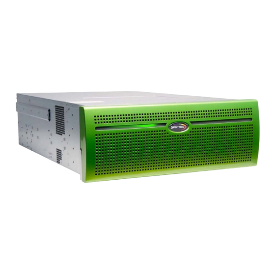
Figure 1 The front view of the Verde master node (front bezel removed). Latch Data drive status LEDs Data drives Power button and system status LEDs Figure 2 The front view of the Verde 2U master node (front bezel removed). September 2017 User Guide—Spectra Verde Array... - Page 23 Note: Since the Verde 2U master nodes do not include a Visual Status Beacon control sled, a disk drive is installed in this position. The power button controls the main AC power for the Verde array. Power button System status LEDs The status LEDs indicate power status, disk and network activity, as well as hardware faults. See System Status LEDs on page 80 for more information. Data drives The Verde 4U master nodes support up to 23 high‐performance disk drives mounted on individual drive sleds in the front of the array. The Verde 2U master nodes support up to 12 data drives. The drive sleds slide into bays in the front of the Verde enclosures and lock in place. The front of each drive sled has a handle for removing the sled from the array and a latch for locking the drive sled in place. Data drive status Two LEDs on each drive sled indicate the status of the drive. One LED is for LEDs drive status while the other shows drive activity. Empty drive sleds When fewer than the maximum number of drives are installed, empty drive sleds are installed in the unused drive bays to prevent contaminants from entering the enclosure and to maintain proper air flow. September 2017 User Guide—Spectra Verde Array...
-
Page 24: Rear View Of Master Nodes
Rear panel Boot drives Data drives Figure 3 The rear view of the Verde 4U master node. Power supplies Rear panel Boot drives Figure 4 The rear view of the Verde 2U master node. September 2017 User Guide—Spectra Verde Array... - Page 25 The rear panel of the Verde master node allows for Ethernet, SAS, USB, and other connections. See Rear Panel of Master Nodes on page 26 for a detailed description. Boot drives The boot drives provide storage for the operating system and Verde user interface. The boot drives are hot swappable which allows for uninterrupted operation during replacement. Data drives The Verde 4U master nodes support up to 12 data drives in the rear of the array. (Verde 4U master Depending on your order configuration, the Verde array may optionally nodes only) contain solid state drives for use as a ZIL. See Write Performance Drives on page 21 for more information. The Verde master nodes do not have data drives in the rear of the array. Note: When fewer than the maximum number of drives are installed, empty drive Empty drive sleds sleds are installed in the unused drive bays to prevent contaminants from (Verde 4U master entering the enclosure and to maintain proper air flow. nodes only) September 2017 User Guide—Spectra Verde Array...
-
Page 26: Rear Panel Of Master Nodes
The Verde arrays include two 10GBase‐T ports. One of the 10GBase‐T ports can Ethernet ports be used for network connectivity on a 10GBase‐T network. The left port of the two 10GBase‐T ports is dedicated as the Verde management port and cannot be used for data transfer. Note: The 10GBase‐T ports auto‐negotiate down to 1000Base‐T. If necessary, you can connect a monitor to the SVGA connector on the Verde Monitor connector master node for troubleshooting purposes. 10 GigE ports The two 10 Gigabit Ethernet (10 GigE) ports can be used for network connectivity on a 10 GigE network. An array can contain both a 10 GigE and 40 GigE network interface card, but cannot use both cards simultaneously. Note: The 10 GigE is optional in the Verde 2U master nodes. Depending on your configuration, there may be SAS cards installed in available SAS ports expansion slots. Each four port SAS card provides connectivity between the (Optional) master node and up to two Verde enterprise expansion nodes. Each two port SAS card provides connectivity between the master node and up to two Verde archive expansion nodes. For information on how to connect cables between the the master node and expansion node, see Spectra Verde Array Installation Guide. September 2017 User Guide—Spectra Verde Array... - Page 27 The Verde management port is used to connect to the browser‐based user Verde interface to configure, manage, and monitor the Verde array. The Verde management port management port cannot be used for data transfer. USB ports If necessary, you can use these ports to connect a USB drive, or USB mouse and USB keyboard to the array for troubleshooting purposes, or to configure the IP addressing for the Verde management port. The serial port is used to connect a primary master node to a secondary master Serial port node in a HotPair configuration. The two master nodes are connected using a null modem cable. For information on connecting cables for a HotPair configuration, see Appendix B HotPair Setup and Configuration starting on page 136. 40 GigE ports The two 40 Gigabit Ethernet (40 GigE) ports can be used for network (Not shown, connectivity on a 40 GigE network. An array can contain both a 10 GigE and optional) 40 GigE network interface card, but cannot use both cards simultaneously. Note: The 40 GigE card is not supported in 2U master nodes. September 2017 User Guide—Spectra Verde Array...
-
Page 28: Front View Of The Verde Enterprise Expansion Node
Beacon control sled corner of the front of the expansion node provides control for the Visual Status Beacon. A disk drive cannot be installed in this position. If the expansion node uses a passive bezel, a disk drive is installed in this position. Power button The power button controls the AC power for the enterprise expansion node. System status LEDs The status LEDs indicate power status, disk and network activity, as well as hardware faults. See System Status LEDs on page 80 for more information. The Verde enterprise expansion node supports up to 23 enterprise disk drives, Data drives or 24 drives if the expansion node uses a passive bezel, mounted on individual drive sleds in the front of the array. The drive sleds slide into bays in the front of the enclosure and lock in place. The front of each drive sled has a handle for removing the sled from the array and a latch for locking the drive sled in place. Data drive status Two LEDs on each drive sled indicate the status of the drive. One LED is for LEDs drive status while the other shows drive activity. Empty drive sleds When fewer than the maximum number of drives are installed, empty drive sleds are installed in the unused drive bays to prevent contaminants from entering the enclosure and to maintain proper air flow. September 2017 User Guide—Spectra Verde Array... -
Page 29: Rear View Of The Verde Enterprise Expansion Node
Figure 7 The rear view of the Verde enterprise expansion node. Component Description The Verde enterprise expansion node includes two power supplies to provide Power supplies N+1 redundancy and fail‐over protection. Each power supply has its own AC power connector. Each power supply has a single LED that lights to indicate when the power is on and functioning normally. SAS connectors The rear panel of the Verde enterprise expansion node has four SAS ports used to connect an expansion node to a master node. Two ports are for primary connections and two ports are for secondary connections. Labels next to each port identify if the port is a primary or secondary connection. For information on how to connect cables between the master node and enterprise expansion node, see the Spectra Verde Array Installation Guide. Data drives Up to 21 data drives can be installed in the rear of the expansion node. Empty drive sleds When fewer than the maximum number of drives are installed, empty drive sleds are installed in the unused drive bays to prevent contaminants from entering the enclosure and to maintain proper air flow. September 2017 User Guide—Spectra Verde Array... -
Page 30: Front View Of The Verde Archive Expansion Node
Front View of the Verde Archive Expansion Node Figure 8 shows the major components on the front of the Verde archive expansion node. Note: For a description of the Verde enterprise expansion node, see Front View of the Verde Enterprise Expansion Node on page Figure 8 The front view of the Verde archive expansion node (Visual Status Beacon removed). Component Description Front bezel The front bezel mounts on the front of the array, and contains the Visual Status (not shown) Beacon light bar, which provides status information for the array. See Front Bezel Visual Status Beacon on page 78 for more information. September 2017 User Guide—Spectra Verde Array... -
Page 31: Rear View Of The Verde Archive Expansion Node
SAS connectors Power supplies Figure 9 The rear view of the Verde archive expansion node. Component Description Fans Five hot‐swappable fans provide the cooling for the Verde archive expansion node. Power supplies The Verde archive expansion node includes two power supplies to provide N+1 redundancy and fail‐over protection. Each power supply has its own AC power connector. Each power supply has a single LED that lights to indicate when the power is on and functioning normally. The rear panel of the Verde archive expansion node has two SAS ports used to SAS connectors connect an expansion node to a Verde master node. For information on how to connect cables between the master node and expansion node, see the Spectra Verde Array Installation Guide September 2017 User Guide—Spectra Verde Array... -
Page 32: Software
Logical volume manager and file system NFS and CIFS servers Operating System The operating system, running on the integrated application server, provides the foundation for all software and applications running on the array. Logical Volume Manager and File System The Verde arrays feature a combined logical volume manager and file system which controls the structure and management of the data storage on the array. The Verde arrays include data verification to protect against corruption. NFS and CIFS Servers The NFS and CIFS servers running on the Verde arrays provide network file system access to host computers over an Ethernet network. NFS and CIFS shares can be accessed by most major operating environments, including Microsoft Windows operating system, Apple Macintosh operating system, UNIX, and Linux. ERDE NTERFACE The Verde user interface provides browser‐based configuration, management, and monitoring of the Verde arrays. The following sections describe the common features that appear in all screens in the user interface. September 2017 User Guide—Spectra Verde Array... -
Page 33: Menus
Chapter 1 — Product Overview Verde User Interface Menus The menu bar appears along the top edge of each screen. Use the menu bar drop‐down menus to navigate through the interface. Menu Status Alerts Power Figure 10 The Dashboard screen of the Verde user interface. The following table provides an overview of the screens available under each menu. The previously selected screen remains displayed until you select another option. Menu Available Options Dashboard The Dashboard navigation link returns you to the Dashboard screen from any other screen in the interface. The Dashboard screen displays the general status of the array, storage pools, volumes, and network connections on the array. Clicking any of the panes on the Dashboard takes you to a details screen for that selection. The Dashboard screen also displays performance metrics of the array. September 2017 User Guide—Spectra Verde Array... - Page 34 AutoSupport Log sets (ASLs) are generated by the array. Users—Provides controls for creating new user accounts for accessing the Verde user interface, as well as changing the password of existing accounts. Note: Creating additional accounts is not supported at this time. Status The Status menu provides access to the tools for monitoring the Verde arrays in your environment. Hardware—Displays information about the array and its components. Selecting the tabs on the Hardware screen displays detailed component status information. NAS > Pools—Displays information about any currently configured storage pools. NAS > Volumes—Displays information about any currently configured volumes on an existing storage pool. Messages—Displays system messages for the array. Performance—Displays performance metrics for storage pools, individual drives, and the CPUs in the integrated server. Reports—Provides controls for generating reports about the configuration and (JavaScript Object status of the array. Reports can be generated in XML or JSON Notation) formats. September 2017 User Guide—Spectra Verde Array...
-
Page 35: Status Icons
Available Options Hardware Provides an at‐a‐glance status of the overall health of the Verde array. Clicking this link takes you to the Hardware screen. Messages Displays the severity, date, and time of the last warning, error, or informational message that was generated. Clicking this link takes you to the Messages screen. Note: This link does not display if there are no current system messages. Power Provides controls for rebooting and shutting down the array. Note: The connection to the user interface is lost after running the reboot command. Wait while the array reboots before attempting to reconnect to the user interface. Status Icons Icons indicate the status of a component and the highest severity level for any system messages, as described in the following table. Icon Meaning Component OK The component is functioning correctly. Information An informational message about a system component is available. Check messages to determine the component. Warning A system component requires attention. Check messages to determine the component. Error A system component experienced an error condition. Check messages to determine the component and its error condition. Unknown The status of a system component cannot be determined. Check messages to determine the component. September 2017 User Guide—Spectra Verde Array... -
Page 36: Supported Browsers
Mozilla ® ® FireFox version 13 or later Apple ® ® Safari version 5 or later Microsoft ® ® Internet Explorer version 8 or later Spectra Logic recommends using Google Chrome to access Notes: the Verde user interface. Pop‐up windows must be enabled to use the Verde user interface. OMMAND NTERFACE The command line interface provides text‐based configuration, management, and monitoring of the Verde arrays. Use the command line interface to perform many of the tasks that are available through the Verde user interface such as configuring storage pools, volumes, and shares; network administration; and monitoring the status of the array. For a full list of the features available in the command line interface, see the Spectra Verde Array Command Line Interface Guide. September 2017 User Guide—Spectra Verde Array... -
Page 37: Chapter 2 - Initial Configuration
HAPTER Initial Configuration This chapter describes the initial setup and configuration steps for the Verde array. Note: If your array is a HotPair configuration, see Appendix B HotPair Setup and Configuration starting on page 177 for specific instructions on how to setup your array. Topic Before You Begin page 38 Connect Ethernet Cables page 38 Power On the Array page 38 Verde Master Nodes and Verde Enterprise Expansion page 38 Nodes Verde Master Node and Verde Archive Expansion page 39 Nodes Configure the Verde Management Port page 40 Automatically Import Activation Keys page 41 Log In to the Verde User Interface page 42 Configure the Data Connection page 44 Create a User page 46... -
Page 38: Connect Ethernet Cables
26 for the location of the Ethernet ports on the rear of the array. OWER N THE RRAY Use the instructions in this section to power on a Verde array. During the power‐on sequence, the Verde array initializes all of its installed components and starts the Verde web server. Verde Master Nodes and Verde Enterprise Expansion Nodes To power on a Verde array, remove the front bezel, and then gently press the power button on the front panel. If your configuration includes both a Verde master node and one or more enterprise expansion nodes, power on all arrays together. The power LED illuminates indicating that power is on. See System Status LEDs on page 109 for more information Power button Power LED Figure 11 Press the power button. September 2017 User Guide—Spectra Verde Array... -
Page 39: Verde Master Node And Verde Archive Expansion Nodes
Verde Master Node and Verde Archive Expansion Nodes If your configuration includes both a Verde master node and one or more Verde archive expansion nodes, power on the expansion node(s) before powering on the master node. To power on a Verde archive expansion node, plug both power cables on the Verde archive expansion node into power outlets near the rear of the chassis. The Verde archive expansion node immediately powers on. Wait approximately four minutes while the expansion node initializes before powering on a Verde master node. To power on a Verde master node, remove the front bezel, and then gently press the power button on the front panel. The power LED illuminates indicating that power is on. See System Status LEDs on page 109 for more information Power button Power LED Figure 12 Press the power button. Do not use the array’s front panel power button to power off the Note: array. See Reboot or Shut down a Verde Array on page 118 to reboot or shut down the array. September 2017 User Guide—Spectra Verde Array... -
Page 40: Configure The Verde Management Port
The default address of the Verde management port is set to 10.0.0.2 with a netmask of 255.255.255.0. If your network is already using this IP address, or you want to configure a different IP address for the management port, use the Verde master node console to configure the Verde management port IP address. If you do not want to change the default management port IP address, skip to Log In to the Verde User Interface on page Note: Using the Verde master node console is the recommended way to change the Verde management port IP address. If you cannot use the console, see Resolving a Management Port IP Address Conflict on page 146 for information on alternate methods. 1. Connect a monitor and USB keyboard to the Verde master node. See Rear Panel of Master Nodes on page 26 to locate the monitor and USB connectors. The Console screen displays. Figure 13 The Console screen. 2. Press CTRL-N. The Configure Management Network Interface screen displays. Figure 14 The Configure Management Network Interface screen. September 2017 User Guide—Spectra Verde Array... -
Page 41: Automatically Import Activation Keys
Default Gateway—Enter the default gateway. 4. Select OK. The console screen displays showing the new IP address. 5. Connect a cable from your network to the Verde management port on the Verde master node. You are now able to connect to the Verde user interface with the IP address displayed in Step 6. Disconnect the monitor and USB keyboard from the Verde array. UTOMATICALLY MPORT CTIVATION Activation keys enable features on the Verde array. They are tied to the serial number of the system for which they are issued, and cannot be used on another array. Renewals of expired activation keys are obtained by contacting Spectra Logic Technical Support (see Contacting Spectra Logic on page 7). The USB device in the Verde documentation kit contains the activation keys for the options that you purchased. Follow these steps to import the keys. If your Verde documentation kit does not contain a USB device, Note: see Manually Enter Activation Keys on page 103 for instructions for manually entering the activation keys. 1. Insert the USB device into a USB port on the back of the array. See Figure on page When the Verde array detects the USB device it automatically imports the activation keys and power cycles the system. September 2017 User Guide—Spectra Verde Array... -
Page 42: Log I Nto The Verde User Interface
> Mark as read. The informational message closes. N TO THE ERDE NTERFACE 1. Open a web browser on a computer on an active network that has access to the Verde array. 2. Enter the IP address of the Verde management port in the browser address bar using either the default address of 10.0.0.2, or the IP address you configured in Configure the Verde Management Port on page The Verde user interface uses a secure connection. Note: 3. Resolve the security certificate warning for the Verde user interface. The warning displays because the Verde arrays do not have a security certificate. This warning only displays if you did not already resolve the Notes: security certificate warning. Consult your browser documentation for instructions on how to resolve the security certificate warning. If you choose not to resolve the warning, you receive the warning about the security certificate each time you access the Verde user interface. The absence of the certificate does not affect functionality. September 2017 User Guide—Spectra Verde Array... - Page 43 Note: password (see Edit a User on page 100). Figure 15 The Verde user interface Login screen. 5. Click > to log in. Note: There is no limit to the number of users who can log in to the interface. Spectra Logic recommends only one person use the interface at a time to avoid conflicting operations. Important The remainder of this guide assumes you are logged in to the Verde user interface. September 2017 User Guide—Spectra Verde Array...
-
Page 44: Configure The Data Connection
By default, you can only create one data connection to the Notes: array. You can configure link aggregation for better performance. You can only use the Verde management port to access the Verde user interface. You cannot use this port for data transfer. If your array contains a 10 GigE network interface card, or 40 GigE network interface card, the 10GBase‐T ports cannot be used for data transfer. Optionally, a 40 GigE card can be installed in 4U master nodes. The configuration steps are the same for both the 10 GigE and 40 GigE cards. While both a 10 GigE and 40 GigE card can be installed in the same Verde array, only one card can be used for data transfer, as the array only allows a single data connection. Use the following steps to configure the data connection for the Verde master node. 1. From the menu bar, select Configuration > Network, or click the Network pane on the Dashboard screen. The Network screen displays with information about the network connections of the array. Figure 16 The Network screen. September 2017 User Guide—Spectra Verde Array... - Page 45 Figure 17 The Edit Data Ports dialog box. 3. Click the option button for the data interface you want to configure. You can only configure one interface. The Aggregate All options allow you to configure a link aggregation using all of the ports of that interface type. Link aggregation uses multiple Ethernet ports, configured with a single MAC address, to improve data transfer speeds. See Link Aggregation Notes on page 149 for more information. If the systemʹs spare onboard Ethernet port is a 10GBase‐T port Note: and the system has a 10GBase‐T HBA, the onboard port is included with the HBA ports in the link aggregation. If you do not want to use the onboard port, only connect cables to the HBA ports. 4. Select either DHCP or Static as the addressing method. If you select static addressing, click the + button and enter the following information: IP Address—Enter a valid IPv4 address. Netmask—Enter the subnet mask. Note: If desired, you can enter Aliases, multiple IP and Netmask addresses assigned to the data port. Use the + button at the bottom of the Edit Data Ports dialog box to increase the number of IP and Netmask addresses. A maximum of 16 additional IP and Netmask addresses can be configured. September 2017 User Guide—Spectra Verde Array...
-
Page 46: Create A User
7. Click Save. Use the instructions in this section to create a new user, edit existing users, change passwords, and configure the session timeout setting. REATE A Use the instructions in this section to create a new user. Description of User Types There are three different types of users in the Verde user interface. Administrator users, monitor users, and login users. Use the table below for a description of the user types. User Description The primary administrator account is created by default. Primary Administrator This account can access the Verde user interface and has full control over all user interface functions. Starting with Verde 4.0, the default username for the primary administrator is Administrator, with the password spectra. If you are upgrading from a previous version of Verde software, the existing administrator account “spectra” is retained. The Administrator account is automatically created without any permissions. Spectra Logic recommends changing the password Note: for the primary administrator. See Edit a User on page 100. September 2017 User Guide—Spectra Verde Array... -
Page 47: Create A User
Note: For Verde software versions older than Verde 4.0, the monitor user account is created by default. If a system running Verde 3.x or older is upgraded to Verde 4.x or later, the existing monitor account is retained. The default username and password are both monitor using all lowercase letters. Note: Spectra Logic recommends that you change the default password for the monitor account. See Edit a User on page 100. Login User A user with Login permissions is able to log into the Verde user interface. Create a User Use the instructions in this section to create users. 1. From the menu bar, select Configuration > Users. The Users screen displays. Figure 18 The Users screen. September 2017 User Guide—Spectra Verde Array... -
Page 48: Next Steps
Figure 19 The New User dialog box. 3. Enter the desired Username for the user. The Username cannot contain capital letters or spaces. 4. Enter the user’s Full Name. 5. Enter and confirm the desired Password for the user. 6. If desired, enter a value for the Session Timeout in minutes. This value cannot exceed 999 minutes. If no value is entered, the array creates the user with the default setting of 60 minutes. Access permissions. See Description of User 7. Select one or more User Types on page 46 for information on each level of user access permission. 8. Click Create to create the new user. TEPS The next steps depend on if you are configuring a Verde array as a standalone product, or if you plan to use your array in conjunction with a BlackPearl system. If you have a standalone Verde array, continue to Configuring Network Attached Storage on page If you plan to use your Verde array with a BlackPearl system, skip to Network File Interface on page 160. September 2017 User Guide—Spectra Verde Array... -
Page 49: Chapter 3 - Configuring Network Attached Storage
HAPTER Configuring Network Attached Storage This chapter describes using the Verde user interface to configure Network Attached Storage (NAS) storage pools, volumes, and shares on a Verde array. Topic Overview of NAS Storage Pools, Volumes, and Shares page 50 Storage Pools page 50 Volumes and Shares page 50 Create a Storage Pool page 50 Create a Volume page 54 Create a Share page 56 Create a CIFS Share page 56 Create an NFS Share page 60 Configure NAS Services page 62 Configure the CIFS Service page 62 Configure the NFI Service page 62 Configure the NFS Service page 62... -
Page 50: Overview Of Nas Storage Pools , V Olumes , And Shares
Storage Pools A storage pool groups a set of physical drives together to create a virtual drive that the operating system treats as a single physical drive. Depending on how it is configured, a storage pool can provide mirrored, single‐parity, double‐parity, or triple‐parity data protection. Higher levels of protection allow for more individual drives to fail before the data is compromised. The costs of higher protection are reduced storage availability and reduced performance. Volumes and Shares Volumes are located on each storage pool. Volumes can be configured with a minimum size and thin provisioned with a maximum size. When you create a volume, you can specify whether it uses compression, and whether the time stamp for files is updated when the file is read (access time). After the volume is created, it can be shared (made available for use by other computers on the network) via either the NFS service or the CIFS service. REATE A TORAGE When creating a new storage pool, keep the following in mind: Each storage pool requires a minimum of one drive. Spectra Logic recommends using eight drives or more in a storage pool to reduce the impact of the overhead. Overhead is the space on the storage pool used to store parity data, and not used for data storage. Drives can only be associated with one storage pool. To create a new storage pool using drives that are already configured in an existing storage pool, you must first delete the existing storage pool as described in Delete a Storage Pool on page 99. You can then create a new storage pool using newly available drives. September 2017 User Guide—Spectra Verde Array... -
Page 51: Create A Storage Pool
Chapter 3 — Configuring Network Attached Storage Create a Storage Pool Any drives not configured in storage pools act as global spare drives. If a drive failure occurs on a Verde array, the array immediately activates a global spare. If the global spare is in the same chassis as the storage pool that claimed it, then when the failed drive is replaced it becomes the new global spare. If the global spare is in a different chassis than the storage pool that claimed it, then when the failed drive is replaced it is rebuilt into the storage pool and the spare drive becomes a global spare again. Spectra Logic recommends leaving at least one drive for a global spare. Use the following steps to create a new storage pool. 1. From the menu bar, select Configuration > NAS > Pools, or click the Pools pane on the Dashboard. The NAS Pools screen displays. Figure 20 The NAS Pools screen. September 2017 User Guide—Spectra Verde Array... - Page 52 Chapter 3 — Configuring Network Attached Storage Create a Storage Pool 2. Select Action > New. A dialog box opens to show the default configuration options for the new pool. Note: The Storage Pool Preview pane does not display until you have selected the disks you want to use in the storage pool Figure 21 The New Pool dialog box. September 2017 User Guide—Spectra Verde Array...
- Page 53 Mirror—Data is striped across two mirrors. Any detected data corruption is corrected using checksums. This type of RAID offers the best performance for small random reads and writes. Single parity—Data is striped across multiple single‐parity arrays, which can tolerate one drive failure without data loss. This type of RAID has faster performance than double‐ and triple‐parity based RAIDs. Double parity—Data is striped across multiple double‐parity arrays, which can tolerate two drive failures without data loss. In most cases, double‐parity provides the best balance between data protection, performance, and storage capacity. Triple parity—Data is striped across multiple triple‐parity arrays, which can tolerate three drive failures without data loss. This type of RAID provides the most data protection. Select Use the slider to maximize either pool capacity or performance, or to mix the two options. Greater capacity means more storage space but slower Optimization Level performance. Higher performance means the pool is faster at reading or writing data with less overall capacity. The Storage Pool Preview pane of the New Pool screen changes as you Note: move the slider between Capacity and Performance to show the impact your changes have on the storage pool. Select Write Use the drop‐down menu to select the number of drives to use in a ZFS Intent Performance Log (ZIL) for this pool. This can increase the write performance of the pool when shared using NFS. This feature is only intended for storage pools with NFS shares and typically has little impact on CIFS share performance. September 2017 User Guide—Spectra Verde Array...
-
Page 54: Create A Volume
Chapter 3 — Configuring Network Attached Storage Create a Volume 4. Click Create. The NAS Pools screen displays. The storage pool is automatically created and is available for use immediately. REATE A OLUME Before you begin using a storage pool to store data, you must create one or more volumes to organize how the information is stored on the pool. After you create a volume, you can share the volume using NFS or CIFS, but not both. If you want to configure the volume to use the NFI service to Note: automatically transfer files from the NAS storage to a BlackPearl system, configure the NFI service before configuring the volume. See Configure the NFI Service on page Use the following steps to create a volume on a storage pool. 1. From the menu bar, select Configuration > NAS > Volumes, or click the Volumes pane on the Dashboard. The Volumes screen displays. Figure 22 The Volumes screen. September 2017 User Guide—Spectra Verde Array... - Page 55 3. Configure the volume as required for your environment. For this option..Do the following... Name Enter a name for the new volume. NFS does not allow spaces in share names. As a result, any spaces in the Note: volume name are replaced by underscores in the corresponding NFS share name. The Verde user interface displays the volume name without the underscores. For example, for a volume named Share One, the corresponding NFS share is named Share_One to external network computers, but it is named Share One in the Verde user interface. Select the storage pool on which to create the volume. If there are multiple Pool storage pools configured on the Verde array, use the drop‐down menu to select the Pool where you want to create the volume. Select the desired unit size from the drop‐down menu and enter a numerical Minimum Size value for the minimum size in the text box to the left of the unit size drop‐down menu. This space is allocated immediately if there is sufficient space available on the storage pool. If there is insufficient space available, volume creation fails. Leave the Minimum Size and Maximum Size blank to create the volume Note: with access to all available space on the storage pool. September 2017 User Guide—Spectra Verde Array...
-
Page 56: Create A Share
The options for the NFI Volume Policy are only used in Note: conjunction with a BlackPearl system. To configure NFI, see Appendix A Network File Interface on page 160. 4. Click Create. The Volumes screen refreshes to show the new volume. REATE A HARE After you create one or more volumes, you can share a volume using either the NFS or CIFS service. Decide which method to use for sharing and follow the appropriate instructions below. Create a CIFS Share, below Create an NFS Share on page 60 Note: Shares are not available until network settings are configured. See Configure the Data Connection on page Create a CIFS Share Spectra Logic recommends using Active Directory to control access to CIFS shares on the Verde arrays. However, if your Windows operating system environment does not use Active Directory, you can enable local administrator status on the array to allow a specified user to access the CIFS shares in a Windows workgroup environment. The username and password configured on the Verde array are used to access the CIFS shares when using a Windows workgroup environment. September 2017 User Guide—Spectra Verde Array... - Page 57 Note: Alternatively, you can create a new user with local administrator status. See Create a User on page 1. From the menu bar, select Configuration > Users. The Users screen displays. Figure 24 The Users screen. 2. Double‐click the row for the user for which you want to enable local administrator status, or select the user, and then select Action > Edit. The Edit User dialog box displays. Figure 25 The Edit User dialog box. 3. Select the CIFS check box to configure the user with local administrator status on the array. If desired, change other settings as described in Edit a User on page 100. September 2017 User Guide—Spectra Verde Array...
- Page 58 Figure 26 The CIFS Shares screen. 2. Select Action > New. The New CIFS Share dialog box displays to show the options for creating a new share. Figure 27 The New CIFS Share dialog box. 3. Use the drop‐down menu to select the Volume you want to share. 4. Set the Name for the CIFS share. This is the name that is displayed in Active Directory configurations. 5. The network address displayed for Path is the address of the share you are currently configuring. The default path allows access to the root of the volume. After creating the CIFS share, you can connect to it using your Note: Windows‐based host and create subdirectories in the share. You can then edit the share and use the Path field to allow access to specific directories by specifying the exact subdirectory (see Edit a Share on page 111). For example, if you enter /home/user in the path field, any user that connects to this CIFS share only has access to the “user” directory, even if the “home” volume contains other directories. September 2017 User Guide—Spectra Verde Array...
- Page 59 Chapter 3 — Configuring Network Attached Storage Create a Share 6. If desired, select Read-only to configure the CIFS share as read only. 7. Click Create. The newly created share is listed on the CIFS Shares screen. Set Permissions for CIFS Share When a CIFS share is created, the default permission is “Everyone”. This allows a user creating the initial shares to easily set the proper permissions for additional users without requiring the Active Directory Domain administrator password. 1. Mount the new CIFS share to your Microsoft Windows operating system host. 2. Using Windows Explorer, right‐click on the CIFS share, and select Properties. The General tab of the Properties window displays. You cannot use the Computer Management panel to set Note: permissions on CIFS shares. Figure 28 The Properties window. September 2017 User Guide—Spectra Verde Array...
-
Page 60: Create An Nfs Share
Create a Share 3. Click Security. The Security tab displays. Figure 29 The Security tab. 4. Add, or remove users, or modify permissions for users as needed for your storage environment. 5. Click OK. Create an NFS Share Use the following steps to create an NFS share. 1. From the menu bar, select Configuration > NAS > Shares > NFS. The NFS Shares screen displays. Figure 30 The NFS Shares screen. September 2017 User Guide—Spectra Verde Array... - Page 61 NFSv3 protocol and properly handles file locking. 5. If desired, enter a comment in the Comment field. This comment only displays on the Verde user interface. 6. In the Host Access Control pane, enter the IP address and permission level of all hosts that you want to access the volume. Hosts not listed are not able to access the volume. In addition to the host IP address, you must include one of the following permission parameters for each host you add to the Verde array. Parameter Description Root Access—The host can access the NFS share with root access to the share. norootsquash This host is used to set permissions for rootsquash users. rootsquash Standard Access—The host can access the NFS share, but does not have root access. Standard access allows write permission to the share, but does not allow the user to delete, modify, or rename files for which they do not have write permission. Read Only—The host can access the NFS share, but cannot write data to the shared volume. For example, entering “192.168.32.25 rootsquash” allows the specified host to access the share with standard access. If you want to allow all hosts to access the share, type * and include the permission parameter. For example, entering “* norootsquash” allows all hosts to access the share with root access. 7. Click Create. The newly created share is listed on the NFS Shares screen. September 2017 User Guide—Spectra Verde Array...
-
Page 62: Configure Nas Services
Configure the CIFS Service There are no configurable settings for the CIFS service at this time. For information about using CIFS shares and joining an Active Directory domain, see Create a CIFS Share on page Configure the NFI Service The NFI service is only used in conjunction with a BlackPearl system. For information on configuring the NFI service, see Network File Interface beginning on page 160. Configure the NFS Service The Verde user interface lets you configure the transmission protocols and number of threads used by the NFS service. Use the following steps to edit the NFS service. 1. Select Configuration > Services to display the Services screen (see Figure 32). 2. Double‐click the NFS service, or select the service, and then select Action > Show Details. The NFS service details screen displays. September 2017 User Guide—Spectra Verde Array... -
Page 63: Configure The Nas Replication Service
Configure the NAS Replication Service Use the instruction in this section to configure the NAS replication service. Note: For both the source array and target array, make sure you have completed the steps in Chapter 2 – Initial Configuration starting on page page 37. 1. Log into the Verde user interface on the source array as described in Log In to the Verde User Interface on page 2. Select Configuration > Services to display the Services screen (see Figure 32 on page 62). 3. Double‐click the Replication service, or select the service, and then select Action > Show Details. The Replication service details screen displays. Figure 34 The Replication service details screen. September 2017 User Guide—Spectra Verde Array... - Page 64 Figure 35 The Add Replication Target dialog box. 5. Enter the IP address or hostname of the target’s management port in the Replication Target field. Note: Do not use http:// or https:// to precede the IP address or hostname. 6. Enter the IP address of the target’s data port in the Replication Target Data IP Address field. Do not use http:// or https:// to precede the IP address or Note: hostname. 7. Enter the username of a user with administrator privileges configured on the target in the Username field. 8. Enter the user password in the Password field, if one is set. Otherwise, leave the field blank. 9. Select the Enable Secure Transfer check box to configure the source array to encrypt the replicated data before transferring it to the target array. Data is encrypted using Secure Socket Layer (SSL). 10. Click Save. September 2017 User Guide—Spectra Verde Array...
-
Page 65: Configure Replication
You cannot use this volume for normal data storage operations, it can only be used Caution as a replication target. Any data in the specified target volume is deleted each time the source array replicates data to the target array. September 2017 User Guide—Spectra Verde Array... -
Page 66: Configure Folders For Replication
You cannot use this volume for normal data storage operations, it can only be used Caution as a replication target. Any data in the specified target volume is deleted each time the source array replicates data to the target array. If the volume does not exist on the target array, it is created. If the volume exists on the target array, a warning message displays informing you that any data currently in the target folder is erased each time data is replicated. Confirm the warning message to continue. September 2017 User Guide—Spectra Verde Array... - Page 67 2. Enter a number for Every _ hours on the hour. This value specifies the interval, in hours, between replicating data. For example, if this value is set to 4, the system replicates data every four hours. 3. Click Create. Create a Daily Schedule 1. Select Daily as the interval for the replication schedule. The dialog box changes to display options for the daily interval setting. Figure 37 The Configure Replication dialog box showing the daily interval options. 2. Enter a time value for Start Time, and include AM or PM after the value. This field is not case sensitive. September 2017 User Guide—Spectra Verde Array...
- Page 68 4. Click Create. Create a Weekly Schedule 1. Select Weekly as the interval for the replication schedule. The dialog box changes to display options for the weekly interval setting. Figure 38 The Configure Replication dialog box showing the weekly interval options. 2. Enter a time value for Start Time, and include AM or PM after the value. This field is not case sensitive. 3. Select one or more days for Every week on:. This determines the day(s) of each week the system replicates data. For example, based on the selections in Figure 38, the system replicates data every Monday, Wednesday, and Friday at 5:00 AM. 4. Click Create. September 2017 User Guide—Spectra Verde Array...
-
Page 69: Chapter 4 - Managing Network Attached Storage
HAPTER Managing Network Attached Storage This chapter describes using the Verde user interface to manage NAS storage pools, volumes, and shares on the array after initial configuration. For initial configuration steps, see Chapter 4 – Managing Network Attached Storage on page 49. Topic Managing Storage Pools page 70 Expand a Storage Pool page 70 Delete a Storage Pool page 71 Managing Volumes page 72 Move a Volume page 72 Edit a Volume page 72 Delete a Volume page 74 Volume Snapshots page 75 Create a Snapshot page 75 Create a Snapshot Schedule page 77 Delete a Snapshot... -
Page 70: Managing Storage Pools
1. From the menu bar, select Configuration > NAS > Pools, or click the Pools pane on the Dashboard. The NAS Pools screen displays (see Figure 18 on page 50). 2. From the list of existing storage pools, select the storage pool you want to expand, and then select Action > Expand. The Expand Pool screen displays options for adding additional drives to the storage pool. Figure 39 The Expand Pool screen. 3. Select the check box next to the type of drive you want to add to the storage pool. By default, the check box for any drive type present in the array is automatically selected. Spectra Logic recommends that you avoid mixing drive types in a pool. 4. Use the slider to increase the number of drives to use in the storage pool. As you make changes, the graphics beneath the slider update to show the impact your changes have on the storage pool. 5. When you are satisfied with the new configuration, click Save. September 2017 User Guide—Spectra Verde Array... -
Page 71: Delete A Storage Pool
Use the following steps to delete a storage pool. 1. From the menu bar, select Configuration > NAS > Pools, or click the Pools pane on the Dashboard. The NAS Pools screen displays (see Figure 18 on page 50). 2. From the list of existing storage pools, select the storage pool you want to delete, and then select Action > Delete. A dialog box displays asking you to confirm the deletion. Figure 40 Confirm the storage pool deletion. 3. Type DELETE in the entry field and click Delete to delete the storage pool. 4. If desired, create a new storage pool that includes the disks no longer in use, as described in Create a New Storage Pool on page September 2017 User Guide—Spectra Verde Array... -
Page 72: Managing Volumes
53). 2. Select the volume you want to move to a different storage pool, and then select Action > Move. The Move Volume dialog box displays. 3. Use the drop‐down menu to select the destination pool for the volume. Figure 41 Select the destination pool for the volume. 4. Click Move. The volume is moved to the selected pool. Edit a Volume After creating a volume, you can edit it to change the volume configuration. Use the following steps to edit a volume. 1. From the menu bar, select Configuration > NAS > Volumes, or click the Volumes pane on the Dashboard. The Volumes screen displays (see Figure 20 on page 53). September 2017 User Guide—Spectra Verde Array... - Page 73 Figure 42 The Edit Volume screen. 3. Change the configuration of the volume as required for your environment. For this option..Do the following... Name Enter a new name for the volume. Notes: NFS does not allow spaces in share names. As a result, any spaces in the volume name are replaced by underscores in the corresponding NFS share name. The Verde user interface displays the volume name without the underscores. For example, for a volume named Share One, the corresponding NFS share is named Share_One to external network computers, but it is named Share One in the Verde user interface. If you change the name of a volume that is being shared, the share point is maintained after the volume name change. Select the desired unit size from the drop‐down menu and enter a numerical Minimum Size value for the minimum size in the text box to the left of the unit size drop‐down menu. This space is allocated immediately if there is sufficient space available on the storage pool. If there is insufficient space available, saving the modified volume fails. September 2017 User Guide—Spectra Verde Array...
-
Page 74: Delete A Volume
1. From the menu bar, select Configuration > NAS > Volumes, or click the Volumes pane on the Dashboard. The Volumes screen displays (see Figure 20 on page 53). 2. Select the volume you want to delete and then select Action > Delete. A dialog box displays asking you to confirm the deletion. Deleting a volumes deletes all data in the volume. This action cannot be undone. Caution Figure 43 Confirm the volume deletion. September 2017 User Guide—Spectra Verde Array... -
Page 75: Volume Snapshots
Volume Snapshots are images of a volume’s configuration and data makeup as they were when the snapshot was generated. Restoring to a previously created snapshot allows you to go “back in time” and restore the volume to the state it was in when the snapshot was created. Snapshots can be useful in restoring a file that was accidentally deleted. Snapshots can be created manually or on a schedule. Volume snapshots are retained on the array until they are manually deleted, or the set Maximum Number of Snapshots limit is reached. When the limit is reached, the oldest snapshot is deleted freeing up capacity held by that snapshot. Snapshots are created instantly without any impact to system performance. Snapshots initially occupy very little space on the storage pool, but grow as data is deleted, because this data must be retained by the snapshot. For example, if you write 100 GB to the volume, and then make a snapshot of that data, the snapshot is only a few kilobytes in size, as it simply points to the existing data on the array. However, if that 100 GB is deleted, the snapshot grows to 100 GB, because it must retain the data. When the snapshot containing the 100 GB of data is deleted, either manually or based on schedule retention, then 100 GB of capacity is made available for new data. Create a Snapshot Use the following steps to create a snapshot. 1. From the menu bar, select Configuration > NAS > Volumes, or click the Volumes pane on the Dashboard. The Volumes screen displays (see Figure 20 on page 53). September 2017 User Guide—Spectra Verde Array... - Page 76 Chapter 4 — Managing Network Attached Storage Volume Snapshots 2. Double‐click the volume you want to use to create a snapshot, or select the volume, and then select Action > Show Details. The details screen for that volume displays. Figure 44 The Volume details screen. 3. On the Volume details screen, select Action > New Snapshot. The New Snapshot dialog box displays. 4. Enter a name for the snapshot in the Name field. Figure 45 The New Snapshot dialog box. 5. Click Create. The Volume details screen displays showing the newly created snapshot. September 2017 User Guide—Spectra Verde Array...
-
Page 77: Create A Snapshot Schedule
Figure 46 The New Snapshot Schedule dialog box showing the hourly interval options. 3. Change the default name of the snapshot schedule, if desired. 4. Enter a number for the Maximum Number of Snapshots. When the maximum number is reached, the system deletes the oldest snapshot. 5. Enter a number for Every _ hours on the hour. This value specifies the interval, in hours, between generating snapshots. For example, if this value is set to 4, the system creates a snapshot every four hours. The maximum setting for this field is 48, where the array creates a snapshot every two days. 6. Click Create. September 2017 User Guide—Spectra Verde Array... - Page 78 3. Change the default name of the snapshot schedule, if desired. 4. Enter a number for the Maximum Number of Snapshots. When the maximum number is reached, the system deletes the oldest snapshot. 5. Enter a time value for Start Time, and include AM or PM after the value. This field is not case sensitive. 6. Enter a number for Every _ days. This value specifies the interval, in days, between generating snapshots. For example, if this value is set to 2, the system creates a snapshot every two days at the time specified in Step 7. Click Create. Create a Weekly Schedule On the Volume details screen (see Figure 44 on page 76), select Action > New Snapshot Schedule. The New Snapshot Schedule dialog box displays. September 2017 User Guide—Spectra Verde Array...
-
Page 79: Delete A Snapshot
4. Enter a number for the Maximum Number of Snapshots. When the maximum number is reached, the system deletes the oldest snapshot. 5. Enter a time value for Start Time, and include AM or PM after the value. This field is not case sensitive. 6. Select one or more days for Every week on:. This determines the day(s) of each week the system generates snapshots. For example, based on the selections in Figure 48 on page 79, the system creates a snapshot every Monday, Wednesday, and Friday at 5:00 AM. 7. Click Create. Delete a Snapshot Use the following steps to delete a snapshot. 1. From the menu bar, select Configuration > NAS > Volumes, or click the Volumes pane on the Dashboard. The Volumes screen displays (see Figure 20 on page 53). September 2017 User Guide—Spectra Verde Array... -
Page 80: Restore To A Snapshot
Figure 49 The Volume details screen showing a snapshot. 3. Select the snapshot you want to delete, and then select Action > Delete Snapshot. A confirmation window displays. Figure 50 Confirm the snapshot deletion. 4. Type DELETE SNAPSHOT in the entry field and click Delete to delete the snapshot. Restore to a Snapshot Use the following instructions to restore a volume to its previous state using a previously generated snapshot. 1. From the menu bar, select Configuration > NAS > Volumes, or click the Volumes pane on the Dashboard. The Volumes screen displays (see Figure 20 on page 53). September 2017 User Guide—Spectra Verde Array... - Page 81 Rollback deletes all data changes made after the snapshot was created, and deletes Caution any snapshots that were saved after the one you are using for the restore process. This action cannot be undone. 4. A dialog box displays, asking you to confirm the rollback. Select Rollback to restore the volume to its state when the snapshot was created. Figure 52 Confirm the volume snapshot rollback. September 2017 User Guide—Spectra Verde Array...
-
Page 82: Retrieve A Single File From A Snapshot
Retrieve a Single File from a Snapshot If you only need to restore a single file, you do not need to restore an entire snapshot. Use the following instructions to retrieve a single file from a snapshot. Note: Use Windows Explorer or Linux/Unix command line to complete this procedure. Use the instructions in this section to retrieve a single file from a snapshot. 1. Using a remote host that has access to the shared volume for which you need to restore a single file, browse to the root directory of the volume. 2. In the shared volume, locate the .snapshots directory. Figure 53 Locate the .snapshots directory. 3. Open the directory. A list of snapshot directories displays. 4. Using its name, locate the snapshot containing the file you need to restore. 5. Open the directory. All files contained in the snapshot display. 6. Locate the file you want to restore and copy it to the appropriate location. ANAGING HARES After creating one or more shares, use the instructions in this section to edit, or delete a share. September 2017 User Guide—Spectra Verde Array... -
Page 83: Edit A Share
Figure 54 The Edit NFS Share dialog box. Make the desired changes (see Create a New Share on page 56 for more information), and click Save. Delete a Share If you do not want to continue sharing a volume (that is, you do not want users accessing the Verde array over a network connection to access the volume), you can delete the share. Use the following steps to delete the share. 1. If you need to delete a CIFS share, from the menu bar, select Configuration > Shares > CIFS. The CIFS Shares screen displays. —OR— If you need to delete an NFS share, from the menu bar, select Configuration > Shares > NFS. The NFS Shares screen displays. 2. Select the share you want to delete, and then select Action > Delete. September 2017 User Guide—Spectra Verde Array... -
Page 84: Managing Nas Replication
Figure 55 Confirm removing the share. NAS R ANAGING EPLICATION After configuring replication, use the instructions in this section to manually start or cancel a volume replication, edit or delete the NAS replication configuration, and to restore replicated files. Manually Start NAS Replication If desired, you can initiate folder replication manually, regardless of the automatic replication schedule configured for the volume. Starting a manual replication begins the replication immediately. Once complete, replication for the folder continues on its previously defined schedule. If the array is in the process of replicating data on a Note: preconfigured schedule, the manual replication begins when the scheduled replication completes. To stop any replication in progress, see Cancel a Replication In Progress on page 1. On the source array user interface, select Configuration > NAS > Volumes. The Volumes screen displays. 2. Double‐click the volume name you want to replicate, or select the folder and select Action > Show Details. The details screen for the volume displays. September 2017 User Guide—Spectra Verde Array... -
Page 85: Cancel A Replication In Progress
Cancel a Replication In Progress If desired, you can cancel any replications currently in progress. Canceling replication stops the replication in progress to the target array. In addition, the target array deletes any data it received during the replication. Use the steps in this section to cancel a replication. 1. On the source array user interface, select Configuration > NAS > Volumes. The Volumes screen displays. 2. Double‐click the volume name for which you want to cancel replication, or select the folder and select Action > Show Details. The details screen for the volume displays. 3. Select Action > Cancel Replication. A confirmation window displays. Figure 57 The Cancel Replication confirmation window. 4. Click Cancel Replication to stop the replication in progress. Any data that was transferred to the target array is deleted. September 2017 User Guide—Spectra Verde Array... -
Page 86: Restoring Files From A Verde Replication Target
From the menu bar, select Configuration > NAS > Volumes. The Volumes screen displays. b. Select the replicated volume and select Action > Edit. The Edit volume name dialog box displays. c. Select the Read Only check box. d. Click Save. 5. Using your host machine, connect to the new share on the Verde replication target array. 6. Copy the needed files from the Verde replication target share. 7. If desired, delete the share once you have restored the needed files. See Delete a Share on page 111. Disable a Folder Replication Use the instructions in this section to prevent any further replication from a volume currently configured to use replication. 1. On the source array user interface, select Configuration > NAS > Volumes. The Volumes screen displays. September 2017 User Guide—Spectra Verde Array... -
Page 87: Edit The Nas Replication Service
Figure 58 The Configure Replication dialog box. 4. Clear the Enabled check box. The other options on the dialog box grey out and become un‐editable (see Figure 58). 5. Click Configure. The volume no longer replicates to the target array. Edit the NAS Replication Service 1. On the source array select Configuration > Services to display the Services screen (see Figure 32 on page 62). 2. Double‐click the Replication service, or select the service, and then select Action > Show Details. The Replication service details screen displays. Figure 59 The Replication service details screen. September 2017 User Guide—Spectra Verde Array... -
Page 88: Delete The Nas Replication Service Configuration
5. If desired, modify the username of a user configured on the target array in the Username field. Note: Because you cannot create additional users at this time, you must use the spectra user account when configuring replication. 6. Enter the user password in the Password field, if one is set. Otherwise, leave the field blank. 7. Confirm the password, if one is set, in the Confirm Password field. Otherwise, leave the field blank. 8. If desired, select the Enable Secure Transfer check box to configure the source array to encrypt the replicated data before transferring it to the target array, or clear the check box to transfer data without encryption. Data is encrypted using Secure Socket Layer (SSL). 9. Click Save. Delete the NAS Replication Service Configuration 1. On the source array select Configuration > Services to display the Services screen (see Figure 32 on page 62). September 2017 User Guide—Spectra Verde Array... - Page 89 Chapter 4 — Managing Network Attached Storage Managing NAS Replication 2. Double‐click the Replication service, or select the service, and then select Action > Show Details. The Replication service details screen displays. Figure 61 The Replication service details screen. 3. Select the replication target in the Replication service details screen, and select Action > Delete. The Delete Replication Target dialog box displays. 4. Click Delete to remove the replication target. The source array no longer replicates data to the target array. Repeat Step 3 and Step 4 to delete additional replication targets, if desired. September 2017 User Guide—Spectra Verde Array...
-
Page 90: Chapter 5 - Configuring A Verde Array
HAPTER Configuring a Verde Array This chapter describes using the Verde user interface to configure the Verde array for operation in your environment. Task Configure Network Connections and Settings page 91 Configure Ethernet Ports page 91 Configure DNS Settings page 93 Configure SMTP Settings page 95 Configure Date and Time page 96 Edit the System Name page 96 Configure Networking Services page 97 Configure the Active Directory Service page 97 Configure the SNMP Service page 98 Configure Users page 100 Description of User Types page 100 Create a User page 100 Edit a User... -
Page 91: Configure Network Connections And Settings
Figure 62 The Network screen. Configure Ethernet Ports This section describes using the Verde user interface to configure the IP addressing for the Ethernet ports in the Verde master node. The array includes two 10GBase‐T ports and two 10 GigE ports on the rear panel (see Figure 5 on page 26). Optionally, a two‐port 40 GigE card can be installed. You can only use the Verde management port to access the Notes: Verde user interface. You cannot use this port for data transfer. By default, you can only create one data connection to the array. You can configure link aggregation for better performance. If your array contains a 10 GigE network interface card, or 40 GigE network interface card, the 10GBase‐T ports cannot be used for data transfer. Optionally, a 40 GigE card can be installed in 4U master nodes. The configuration steps are the same for both the 10 GigE and 40 GigE cards. While both a 10 GigE and 40 GigE card can be installed in the same Verde array, only one card can be used for data transfer, as the array only allows a single data connection. September 2017 User Guide—Spectra Verde Array... - Page 92 Verde user interface. Contact your system administrator to determine the DHCP address for the management port. If you select static addressing, enter the following information: IP Address—Enter a valid IPv4 address. Netmask—Enter the subnet mask. Default Gateway—Enter the default gateway. 4. Change the MTU value, if desired. If you set the MTU value to something other than 1500, ensure that your switch configuration supports larger MTU settings, as well as all the hosts on the network. September 2017 User Guide—Spectra Verde Array...
-
Page 93: Configure Dns Settings
Clear an Ethernet Configuration In some cases, it may be useful to delete an existing Ethernet configuration by clearing it. Use the instruction in this section to clear an Ethernet configuration. 1. From the menu bar, select Configuration > Network, or click the Network pane on the Dashboard screen. The Network screen displays (see Figure 62 on page 91). 2. Select the row of the configuration you want to clear and then select Action > Clear from the menu bar. A confirmation window displays. 3. Click Delete to clear the Ethernet configuration. Configure DNS Settings The DNS settings on the Verde array are used to allow domain name lookup on the array. Use the following instructions to enter DNS information on the array. 1. From the menu bar, select Configuration > Network, or click the Network pane on the Dashboard screen. The Network screen displays (see Figure 62 on page 91). September 2017 User Guide—Spectra Verde Array... - Page 94 Configure Network Connections and Settings 2. In the DNS pane of the Network screen, double‐click the single row, or select the single row and then select Action > Edit from the menu bar. The Edit DNS screen displays. Figure 64 Edit DNS information. 3. Select DHCP to have the array determine the address of name servers and search domains automatically. —OR— Select Manual to enter information for name servers and search domains manually. Note: The buttons for DHCP and Manual are only usable when the Verde management interface is configured as DHCP. If the management interface is set to a static IP address, the buttons are greyed out and the information must be entered manually. 4. If you selected Manual, enter the following information: a. Enter the IP address of one or more name servers in the Name Servers field. b. Enter the URL of one or more search domains in the Search Domains field. 5. Click Save. September 2017 User Guide—Spectra Verde Array...
-
Page 95: Configure Smtp Settings
SMTP server and then select Action > Edit. The Email dialog box displays. Figure 66 The Email dialog box. 3. Enter the SMTP Server and SMTP Port information. 4. Using the drop‐down menu, select the SMTP Authentication Type required by your mail server. 5. If your SMTP server uses TLS (Transport Layer Security) authentication, select the Enable TLS Authentication check box and enter the required Username and Password information. 6. Enter an email address in the From Address field. This is the email address that displays as the sender whenever the system generates an email. This email address should uniquely identify the Verde master node to assist in troubleshooting and be recognized by the SMTP server as a valid domain address. 7. Click Save. September 2017 User Guide—Spectra Verde Array... -
Page 96: Configure Date And Time
> Edit. The Time Settings dialog box displays. Figure 68 The Time Settings dialog box. 3. Select Manual or NTP. a. If you select Manual, enter the current time in the Time field. Enter either 12‐hour time values and include AM or PM, or use 24‐hour time values. Click the Date field. A calendar appears. Select the current date. b. If you select NTP, enter the NTP server information for the Primary Server. If desired, enter the NTP server information for the Secondary Server. 4. Click Save. Edit the System Name 1. From the menu bar, select Configuration > Network, or click the Network pane on the Dashboard screen. The Network screen displays. September 2017 User Guide—Spectra Verde Array... -
Page 97: Configure Networking Services
Figure 69 The Edit System Name dialog box. 3. Enter the desired Name for the system, and click Save. ONFIGURE ETWORKING ERVICES Use the following instructions to configure networking services on the Verde array. For instructions on configuring NAS services, see Configure Network Connections and Settings on page Configure the Active Directory Service 1. From the menu bar, select Configuration > Services. The Services screen displays. Figure 70 The Services screen. 2. Double‐click the Active Directory row, or select the Active Directory row and select Action > Show Details. The Active Directory details screen displays. September 2017 User Guide—Spectra Verde Array... -
Page 98: Configure The Snmp Service
5. Enter the name of the Active Directory Domain you want to join. 6. Enter the Username and Password for a user authorized to join the specified domain. Note: You must enter the user name and password each time the Verde array joins an Active Directory domain. The array does not save this information. 7. Click Join Domain. Configure the SNMP Service The Verde user interface lets you configure the community and client list of the SNMP service to remotely monitor the Verde array using a network node manager program. Use the following steps to edit the SNMP service. 1. Select Configuration > Services to display the Services screen (see Figure 70 on page 97). 2. Double‐click the SNMP service, or select the service, and then select Action > Show Details. The SNMP service details screen displays. September 2017 User Guide—Spectra Verde Array... - Page 99 Enter a community string value in the Community String field. This community string is set for each client. The clients monitor SNMP notifications for any that use the string specified here. Repeat Step a through Step e as needed to add additional clients. 8. Click Save. Download the MIB File If you want to communicate with the array using SNMP, you must first download the Verde MIB (Management Information Base) file, and load ® the file into compatible network node manager programs, such as HP ® OpenView network node manager. 1. Select Configuration > Services to display the Services screen (see Figure 70 on page 97). 2. Double‐click the SNMP service, or select the service, and then select Action > Show Details. The SNMP service details screen displays. September 2017 User Guide—Spectra Verde Array...
-
Page 100: Configure Users
Figure 73 Download the MIB file. 4. Load the file into the network node manager program. 5. You can now use your network node manager program to communicate with the Verde master node, using the settings configured in Configure Network Connections and Settings on page ONFIGURE SERS Use the instructions in this section to create a new user, edit existing users, change passwords, and configure the session timeout setting. Description of User Types See Description of User Types on page 46 for information about each user type. Create a User To create a user, see Create a User on page Edit a User 1. From the menu bar, select Configuration > Users. The Users screen displays a list of all configured users (see Figure 18 on page 47). September 2017 User Guide—Spectra Verde Array... -
Page 101: Delete A User
The new password does not take effect until after you log out of Note: the Verde user interface (see Exit the BlackPearl User Interface on page 252). 6. If desired, enter a value for the Session Timeout in minutes. This value cannot exceed 999 minutes. 7. Select one or more User Access permissions. See Description of User Types on page 100 for information on each level of user access permission. 8. Click Save. Delete a User 1. From the menu bar, select Configuration > Users. The Users screen displays a list of all configured users (see Figure 18 on page 47). 2. Select the user you want to delete, and then select Action > Delete. A confirmation window displays. 3. Click Delete to delete the user. September 2017 User Guide—Spectra Verde Array... -
Page 102: Configure Certificates
If desired, you can install signed, trusted SSL certificates for the management port so that you no longer need to pass the security check when accessing this port. Use the instructions in this section to install an SSL certificate. 1. From the menu bar, select Configuration > Certificates. The Certificates screen displays. Figure 75 The Certificates screen. 2. Select the Management row, and then select Action > Import Certificate. The Import Certificate dialog box displays. Figure 76 The Import Certificate dialog box. 3. From your source SSL certificate file, copy the certificate portion of the file into your host’s cache, and then paste the contents into the Certificate entry box. Note: The certificate must be in PEM format. September 2017 User Guide—Spectra Verde Array... -
Page 103: Manually Enter Activation Keys
Failure to enter the keys in the proper order causes an error. Use the instructions below to enter an activation key. 1. From the menu bar, select Support > Activation Keys to display the Activation Keys screen. Any previously entered keys are listed. Figure 77 The Activation Keys screen. 2. Select Action > New. The Enter Activation Key dialog box displays. Figure 78 The Enter Activation Key dialog box. September 2017 User Guide—Spectra Verde Array... - Page 104 3. Locate the capacity key listed on the Software Activation Key Certificate included in your shipping box. There are three types of capacity keys. Key Type Description Enables the specified number of enterprise drives EM_NAS_SAS_COUNT present in the Verde master node and Verde expansion node. Enables the specified number of archive drives EM_NAS_SATA_COUNT present. Enables the specified number of SSD drives EM_NAS_SSD_COUNT present in the master node. 4. Enter the key, exactly as provided, in the Activation Key field and click Create to save the key on the array. The Activation Keys screen displays with the newly entered key listed. If necessary, repeat Step 3 and Step 4 to enter any additional capacity keys. 6. Locate the EM_NAS product key listed on the Software Activation Key Certificate included in your shipping box. 7. Enter the key, exactly as provided, in the Activation Key field and click Create to save the key on the array. The Verde user interface changes to reflect the installation of the product key. 8. Enter any additional keys that may be included on the Software Activation Key Certificate, such as the Software Update key. September 2017 User Guide—Spectra Verde Array...
-
Page 105: Chapter 6 - Monitoring A Verde Array
HAPTER Monitoring a Verde Array This chapter describes procedures for day‐to‐day monitoring and operation of a Spectra Verde array. Topic Monitor the Verde Arrays page 106 Front Bezel Visual Status Beacon page 107 Configure the Visual Status Beacon Color page 108 System Status LEDs page 109 View System Messages page 110 View the Status of Hardware Components page 111 View the Status of Pools page 112 View the Status of Volumes page 113 View the Status of Shares page 113 View the Status of Services page 113 View Performance Metrics page 115 View Reports... -
Page 106: Monitor The Verde Arrays
Note: The front bezels in Verde 2U arrays do not include a Visual Status Beacon light bar. System messages provide important information about the Verde arrays and their operation (see View System Messages on page 110 for more information). Icons on the System screen provide overall status of the hardware components in each group (see View the Status of Hardware Components on page 111 for more information). Clicking the text next to each icon displays detailed status information for the components in the group. You can also use the Verde user interface to do the following on the Verde arrays: View the status of services (see View the Status of Services on page 113). View performance metrics for the drives, CPUs, storage pools, and network (see View Performance Metrics on page 115). View the current network configuration settings (see Configure Network Connections and Settings on page 91). Reboot or shut down the array (see Reboot or Shut down a Verde Array on page 118). September 2017 User Guide—Spectra Verde Array... -
Page 107: Front Bezel Visual Status Beacon
Note: normally can be changed on the Hardware screen. See Configure the Visual Status Beacon Color on page 108 for more information. The array is experiencing a Warning condition. Log in to Yellow Scroll the Verde user interface to determine the cause of the warning. The array is experiencing an Error condition. Log in to Red Scroll the Verde user interface to determine the cause of the error. The array is currently powering on and performing self‐ Rainbow tests. The beacon feature was activated for this array. This can Flashing Blue help you identify a specific array when you have more than one array in your environment. See View the Status of Hardware Components on page 111 for instructions on activating the beacon. The Visual Status Beacon lost communication with the Pulsing Red array. This can occur if the array experiences a software hang. Note: Other patterns may display if the front bezel is not properly seated on the array. September 2017 User Guide—Spectra Verde Array... -
Page 108: Configure The Visual Status Beacon Color
3. Click the colored box next to Select Bezel Color. The color picker window displays. Figure 79 Use the color picker to set the color displayed on the Visual Status Beacon when the array is operating normally. 4. Use the color picker to select the color to display when the array is operating normally. Optionally, you can enter an HTML color code in the entry field. Spectra Logic recommends against using yellow or red, so that Note: you can more easily determine if the array is in a warning or error state. 5. Click Choose to set the color of the Visual Status Beacon. September 2017 User Guide—Spectra Verde Array... -
Page 109: System Status Leds
Figure 80 System status LEDs. Function Power Indicates if the unit is powered on. Hard Drive Indicates boot drive activity. To see the activity of a data drive, see Data drive status LEDs on page Network 1 Indicates network activity on the Verde management port. Network 2 Indicates network activity on data interface 1. This LED also shows network activity if data interface 1 is configured in link aggregation mode. If the LED is blinking red, it indicates a fan failure. Log into the Verde Fan Failure / Overheat user interface to determine which fan failed. If the LED is solid red, it indicates an overheat condition. Log into the Verde user interface to view the status of the system. If the problem persists, contact Spectra Logic Technical Support. See Contacting Spectra Logic on page Power Failure Indicates a power supply failure. Log into the Verde user interface to determine which power supply failed. September 2017 User Guide—Spectra Verde Array... -
Page 110: View System Messages
Notifies the user of a failure that may adversely impact the Warning Verde array. Critical Notifies the user of a failure that caused significant adverse impact to the Verde array. The status bar displayed at the bottom of all Verde interface screens shows the severity and generation date and time for the most recent message. If there are no system messages, this text does not display. Figure 81 A system message displayed on the Verde user interface status bar. 1. From the menu bar, select Status > Messages, or click the Messages link on the status bar, to display the Messages screen. Figure 82 The Messages screen. September 2017 User Guide—Spectra Verde Array... -
Page 111: View The Status Of Hardware Components
Mark all as read. Note: Messages can also be marked as unread using the Action menu. View the Status of Hardware Components The Verde user interface lets you monitor the status of hardware components without having direct physical access to the Verde arrays. This is especially useful when your Verde arrays are operating in a “lights out” data center. Check the Verde user interface regularly to ensure that you always know the status of the hardware components. 1. From the menu bar, select Status > Hardware or click the Hardware pane on the Dashboard, or click the Hardware link on the status bar. The Hardware screen displays. Toolbar Beacon button Figure 83 The Hardware screen (Verde 4U master node shown). September 2017 User Guide—Spectra Verde Array... -
Page 112: View The Status Of Pools
System memory status and size Status, manufacturer, model, size, and serial number for each DOM boot drive 3. Click Turn Beacon On to cause the Visual Status Beacon light on a Verde array to flash blue. This is useful when you have multiple arrays and need to replace a component. Click the button a second time to stop the light from flashing. View the Status of Pools The Pools screen provides status information about all storage pools that are configured on the array. 1. From the menu bar, select Status > NAS > Pools to display the Pools screen. 2. The status of each storage pool is indicated by the status icons on the left side of the screen. Figure 84 The Pools screen. September 2017 User Guide—Spectra Verde Array... -
Page 113: View The Status Of Volumes
View the Status of Shares The Shares screen provides status information about all shares that are configured on the array. 1. From the menu bar, select Configuration > NAS > Shares > CIFS to display the CIFS Shares screen, or select Configuration > NAS > Shares > NFS to display the NFS Shares screen. 2. The status of each share is indicated by the status icons on the left side of the screen. Figure 86 The CIFS Shares screen. View the Status of Services The Services screen provides status information about services that are currently installed on the Verde master node. September 2017 User Guide—Spectra Verde Array... - Page 114 Monitor the Verde Arrays 1. From the menu bar, select Configuration > Services to display the Services screen. Figure 87 The Services screen. This column... Shows... Name The name of the service running on the array. State The status of the service on the Verde array. Starting—The service is starting up. Operational—The service is running. Stopped—The service is not running. Enabled Whether or not the service is enabled at system startup. Yes—Service automatically starts when the array is powered on. No—Service does not start when the array is powered on. September 2017 User Guide—Spectra Verde Array...
-
Page 115: View Performance Metrics
1. From the menu bar, select Status > Performance or click the Performance pane on the Dashboard. The Performance screen displays. Figure 88 The Performance screen. 2. Select Pools, Drives, CPUs, or Network to display performance information about the selected component. Note: If you select Pools, Drives, or Network, use the Pool, Disk, or Interface drop‐down menu to select a specific storage pool, disk drive, or network connection to display. 3. Select the time interval using the Resolution drop‐down menu. The data can be displayed in 5 second increments (5 minutes total) or 60 second increments (25 hours total). 4. Select or clear options under Select elements to plot to indicate which graph lines to display. The graph updates as soon as you select or clear an option. 5. Set the performance graph’s time values to your local time zone using the Time zone menu. All entries are listed in +/‐ GMT. September 2017 User Guide—Spectra Verde Array... - Page 116 The range indicator graph continues to display the original range of data, with the section that is currently being shown on the main graph highlighted. Main graph Range indicator graph Highlighted section currently displayed on main graph Figure 89 Highlight a section of the graph to show it in greater detail. 8. Click Reset View to reset the main graph to the default view. September 2017 User Guide—Spectra Verde Array...
-
Page 117: View Reports
Chapter 6 — Monitoring a Verde Array Monitor the Verde Arrays View Reports The Reports screen lets you to generate reports on all aspects of the Verde array, including component status, and configuration. Reports can be saved in either JSON or XML format. 1. From the menu bar, select Status > Reports to display the Reports screen. Figure 90 The Reports screen. 2. Select check boxes next to the report(s) you want to generate. You can use the All or None buttons at the bottom of each report Note: group to select or clear that group of reports. The All and None buttons at the bottom of the screen select or clear all reports shown on the screen. 3. Select the Format for the report(s). Only one format can be selected. 4. Click Save. The array saves the selected reports to your local host. 5. Open a report using a compatible program. September 2017 User Guide—Spectra Verde Array... -
Page 118: Reboot Or Shut Down A Verde Array
Reboot or Shut down a Verde Array EBOOT OR HUT DOWN A ERDE RRAY This section discusses rebooting or shutting down an array. Using the Verde User Interface Use the following instructions to reboot or shut down an array using the Verde user interface. 1. Click the power icon in the lower right‐hand corner of any screen in the Verde user interface. The Power screen displays. Power icon Figure 91 The Power icon. 2. Click either Reboot or Shutdown. 3. A confirmation screen appears. Confirm the selection to perform the reboot or shutdown. September 2017 User Guide—Spectra Verde Array... -
Page 119: Power-Cycle Reset
Verde Archive Expansion Nodes To power‐cycle reset a Verde archive expansion node, disconnect the power cables at the rear of the chassis from the power outlet. After a few moments, connect the cables again to power on the expansion node. Do not disconnect the power cables to turn off a Verde archive expansion node Caution unless you are specifically instructed to do so by Spectra Logic Technical Support. XIT THE ERDE NTERFACE To exit the Verde user interface, close the browser or click Logout on the right side of the menu bar. This ends the session. -
Page 120: Chapter 7 - Using Autosupport
HAPTER Using AutoSupport This chapter describes using the Verde user interface to configure the support features of the Verde array. Task About AutoSupport page 121 Enter Contact Information page 121 Configure Mail Recipients page 122 Add a New Recipient page 122 Edit a Mail Recipient page 123 Send a Test Email page 124 Delete a Mail Recipient page 125 Log Sets page 125 Configure a Log Set Schedule page 126 Manually Generate Log Sets page 127 Email a Log Set page 127 Download a Log Set page 128 Delete a Log Set page 128... -
Page 121: About Auto Support
About AutoSupport BOUT UPPORT AutoSupport lets the Verde master node automatically contact mail recipients when the array generates certain kinds of messages. You can also use it to generate AutoSupport Log (ASL) sets for use by Spectra Logic Technical Support. The array can email ASL sets to Spectra Logic or mail recipients when critical events occur, or on a monthly basis. NTER ONTACT NFORMATION Contact information helps Spectra Logic in contacting the administrator of the Verde arrays during troubleshooting. Entering the contact information is typically a one‐time‐only process. 1. From the menu bar, select Support > Contact Information to display the Contact Information screen. 2. Click New in the Customer Contact Information pane. The New Contact Information dialog box displays. Figure 92 The New Contact Information dialog box. 3. Enter the requested information and click Create. September 2017 User Guide—Spectra Verde Array... -
Page 122: Configure Mail Recipients
You can configure AutoSupport to email system messages and log sets as they are generated, to selected recipients. All log sets and messages are sent to a previously configured mail recipient. You cannot send log sets or messages directly to an email address. Use the Mail Recipients screen to add, edit, or delete mail recipient accounts. Figure 93 The Mail Recipients screen. Add a New Recipient Use these instructions to add a new mail recipient. 1. From the menu bar, select Configuration > Mail Recipients to display the Mail Recipients screen. 2. Select Action > New. The New Mail Recipient dialog box displays. Figure 94 The New Mail Recipient dialog box. September 2017 User Guide—Spectra Verde Array... -
Page 123: Edit A Mail Recipient
Select from the listed message types, which severities of message this mail Select the message recipient should receive. The Verde master node automatically sends email severities you want messages of the selected severity to the recipient when they are generated. to receive Note: For the mail recipient to receive all messages generated by the array, select all boxes. 4. Click Create to save the information. The Mail Recipients screen re‐ displays with the new mail recipient added to the list of mail recipients. Repeat Step 1 on page 122 through Step 4 to configure additional mail recipients. Edit a Mail Recipient Use the following steps to edit a mail recipient. 1. From the menu bar, select Configuration > Mail Recipients. The Mail Recipients screen displays with any already configured mail recipients listed. September 2017 User Guide—Spectra Verde Array... -
Page 124: Send A Test Email
Figure 95 Edit the information for the selected mail recipient. 3. Change the information for the recipient as required and then click Save. See Add a New Recipient on page 122 for a explanation of the options. Send a Test Email Use the following steps to send a test email to a mail recipient. 1. From the menu bar, select Configuration > Mail Recipients. The Mail Recipients screen displays with any already configured mail recipients listed. 2. From the list of mail recipients, select the name of the recipient you want to send a test email, and then select Action > Send test email. The Verde master node immediately sends a test email to the selected account. 3. Verify the user received the email from the Verde master node. If the email is not received, verify that you entered the mail recipients email address and the SMTP server settings correctly (see Configure SMTP Settings on page 95). September 2017 User Guide—Spectra Verde Array... -
Page 125: Delete A Mail Recipient
1. From the menu bar, select Configuration > Mail Recipients. The Mail Recipients screen displays with any already configured mail recipients listed. 2. From the list of mail recipients, select the name of the recipient you want to delete, and then select Action > Delete. A dialog box displays asking you to confirm the deletion of the mail recipient. Figure 96 Delete the selected mail recipient. 3. Click Delete to confirm the deletion. The Verde arrays automatically generate log sets when errors occur. Log sets can also be generated manually, or generated on a schedule. The Verde arrays generate three types of log sets: Log Sets contain information about the configuration and status of the Verde array and are used for general troubleshooting. Log sets can be mailed to configured mail recipients or to Spectra Logic Technical Support. Statistic Log Sets contain performance data about the array and are used by Spectra Logic Technical Support for in‐depth troubleshooting. Statistic log sets are too large to mail directly from the array and must be downloaded. Kernel Log Sets are generated whenever a process on the array fails. This log set cannot be generated manually. September 2017 User Guide—Spectra Verde Array... -
Page 126: Configure A Log Set Schedule
1. From the menu bar, select Support > Logs. The Logs screen displays. 2. Select Action > New Log Set Schedule. The New Log Set Schedule dialog box displays. Figure 98 The New Log Set Schedule dialog box. 3. Enter a time value for Start Time, and include AM or PM after the value. This field is not case sensitive. 4. Select one or more days for Every week on:. This determines the day(s) of the week the system generates log sets. 5. Click Create. The Logs screen displays showing the newly created Log Set Schedule. September 2017 User Guide—Spectra Verde Array... -
Page 127: Manually Generate Log Sets
Email a Log Set Use the instructions in this section to email a log set. Note: You must configure the SMTP settings on the array before you can send emails. See Configure SMTP Settings on page 95 to configure the SMTP settings. 1. From the menu bar, select Support > Logs. The logs screen displays. 2. Select the log set you want to email, and then select Action > Email. The Email Log Set dialog box displays. Statistic Log Sets are too large to email from the array, and must Note: be downloaded. See Download a Log Set on page 128. Figure 99 The Email Log Set dialog box. 3. Select the mail recipients you want to receive the log set, and click Email. September 2017 User Guide—Spectra Verde Array... -
Page 128: Download A Log Set
2. Select the log set you want to delete, and select Action > Delete. A confirmation window displays asking you to confirm the action. 3. Click Delete to delete the log set. 4. Optionally, use one of the following commands to delete log sets in bulk: Command Description Action > Delete All Log Sets Deletes all log sets present on the array. Action > Delete All Statistic Log Sets Deletes all statistic log sets on the array. Action > Delete All Kernel Logs Deletes all kernel log sets on the array. September 2017 User Guide—Spectra Verde Array... -
Page 129: Chapter 8 - Maintaining A Verde Array
HAPTER Maintaining a Verde Array This chapter describes the maintenance procedures for a Verde array. Task Data Integrity Verification page 130 Initiate RSC Backup page 131 Compression page 131 Accessing the Technical Support Portal page 132 Create an Account page 132 Log Into the Portal page 133 Configuring Automated Software Upload page 134 Updating Software page 135 Check the Current Software Version page 135 Check the Currently Released Verde Software page 136 Version Download and Stage the Updated Software page 137 Install the Update page 138 Installing a New Data Drive... -
Page 130: Data Integrity Verification
Figure 100 The Data Integrity Verification screen. 2. Select the storage pool you want to scan with data integrity verification, and then select Action > Start. 3. A confirmation screen displays. Click Start Data Verification to start the scan. 4. The Data Integrity Verification screen displays, showing that the selected pool is being scanned for corruption. The screen shows the estimated time until the scan is complete, as well as the total time elapsed since the scan started. Figure 101 The Data Integrity Verification screen showing a scan in progress. 5. To stop the scan before it completes, select the storage pool currently being scanned, and then select Action > Cancel. September 2017 User Guide—Spectra Verde Array... -
Page 131: Initiate Rsc Backup
1. From the menu bar, select Support > Tools > Data Integrity Verification. The Data Integrity Verification screen displays (see Figure 100 on page 130). 2. Select Action > Initiate RSC Backup. A confirmation screen displays. 3. Click Initiate RSC Backup to manually save the current system configuration. OMPRESSION The Verde array can be configured to compress data as it is written to the array. If the data being written is compressible there is an increase in write performance to the array, which is dependent on how much compression occurs on the data being written to the array. The data compression process uses CPU cycles to perform the compression. If compression is enabled and non‐compressible data is written to the array, the compression process may use an excessive number of CPU cycles, slowing the overall performance of the array. To determine the current CPU usage of the array, see View Performance Metrics on page 115. September 2017 User Guide—Spectra Verde Array... -
Page 132: Create An Account
ORTAL The Spectra Logic Technical Support portal provides access to the Knowledge Base, the current version of Verde software for the array, and additional service and support tools. You can also open or update a support incident and upload log files. Create an Account Access to User Guides and compatibility matrices does not require you to create an account. You must create a user account and log in to access Release Notes or repair documents, to download the latest version of Verde software, or to open a support incident. Note: If you have multiple Spectra Logic products, the serial numbers for all products are associated with your account. If you do not see the serial numbers for all of your products when you log in, contact Technical Support (see Contacting Spectra Logic on page 1. Access the Technical Support portal login page at support.spectralogic.com. 2. On the home page, click sign up. Figure 102 The Spectra Logic Technical Support portal home page. September 2017 User Guide—Spectra Verde Array... -
Page 133: Log Into The Portal
If you have an invitation, follow the link and enter the invitation code. Figure 103 Follow the link to enter your invitation code or enter your registration information. If you do not have an invitation, enter the requested information to create your account. When you are finished, click Sign Up. When the account is approved, you receive an email with a link to setup your initial password. Use your email address and the password provided in the email to log in to your account. After you log in, you can change your password if desired. Log Into the Portal Access the Technical Support login page at support.spectralogic.com. Use your email address and password to log into the Technical Support Portal. September 2017 User Guide—Spectra Verde Array... -
Page 134: Configuring Automated Software Upload
4. Use the drop‐down menu to select the Check for updates frequency. 5. Optionally, select the Email Notifications Only check box to only receive an email when an updated software package is available instead of automatically downloading the file. 6. Select either Spectra Logic or Use Proxy as the Upload From location. Important Spectra Logic recommends using the Spectra Logic package server. If you select Use Proxy, enter the following information: Proxy IP Address—Enter a valid IPv4 address. Proxy Port—Enter the port used to access the proxy server. 7. Click Save. September 2017 User Guide—Spectra Verde Array... -
Page 135: Pdating Software
Update on page 138. If you were notified that an update is required, but the update did not download automatically, skip to Download and Stage the Updated Software on page 137. If you do not know if the array needs an update installed, continue with Check the Current Software Version. Check the Current Software Version Use the following steps to determine the current software version running on your Verde master node. 1. From the menu bar, select Support > Software. The Software screen displays. 2. The current software version is listed next to Current Version in the Software Update pane. Figure 105 The current Verde software version. September 2017 User Guide—Spectra Verde Array... -
Page 136: Check The Currently Released Verde Software Version
Check the Currently Released Verde Software Version Follow these steps to check the currently recommended Verde software version: 1. Log into your user account on the Technical Support portal at https://support.spectralogic.com. Note: See Create an Account on page 132 for information about creating an account and accessing the Technical Support portal. 2. Select Downloads > Product Software. 3. On the Product Software page, locate your the Verde in the Spectra Product column. The currently released Verde version is listed in the Current Version column. Figure 106 The Product Software screen. 4. Compare the Current Version available for the Verde array to the version installed on the array. September 2017 User Guide—Spectra Verde Array... -
Page 137: Download And Stage The Updated Software
Chapter 8 — Maintaining a Verde Array Updating Software Download and Stage the Updated Software Use the instructions in this section to download and install the updated software for the Verde array. 1. Log into your account on the Technical Support portal at https://support.spectralogic.com. 2. Select Downloads > Product Software. The Product Software Screen displays. Figure 107 The Product Software screen. 3. Locate the Verde array in the Spectra Product column. The currently released Verde software version is listed in the Current Version column. 4. Click the name of the Verde package. The package begins downloading through your web browser. Do not unzip the downloaded file. September 2017 User Guide—Spectra Verde Array... -
Page 138: Install The Update
Figure 108 The Software Update screen with an available software package listed. Install the Update 1. Discontinue all file storage operations on the Verde array. The array automatically reboots as part of the update process. 2. From the menu bar, select Support > Software to display the Software screen. The Software screen displays with the software upload file staged to the system. Figure 109 The Software Update screen with a software package staged to the system. September 2017 User Guide—Spectra Verde Array... -
Page 139: Ensure Esd Protection
Leave the drive in its anti-static bag until you are ready to install it. Do not place the un-bagged drive on any metal surfaces. September 2017 User Guide—Spectra Verde Array... -
Page 140: Install The Drive
Remove the Empty Drive Sled Use the following steps to remove an empty drive sled. 1. Put on an anti‐static wristband and attach it to the anti‐static mat or an unpainted metallic surface. Continue to wear the wristband throughout the entire replacement procedure. 2. Locate the empty drive bays where you want to install a new drive. Note: Do not install a drive in slot 1, which is the top left drive in the front of the array. This slot is reserved for the Visual Status Beacon control sled. The images below show a normal drive sled in slot 1 for clarity. 3. Slide the drive sled locking tab to the right to release the drive sled handle. Handle Figure 111 Slide the tab to the right to release the drive sled handle. September 2017 User Guide—Spectra Verde Array... - Page 141 Figure 112 Pull the sled out of the array. 5. Dispose of the empty sled in accordance with your company’s guidelines. Install the New Drive 1. New drives are shipped installed in a drive sled. Slide the locking tab on the front of the drive sled to the right to release the handle. 2. With the drive handle in the open position, slide the drive sled into the chassis until the front of the drive sled is flush against the chassis. The drive sled slides in easily; do not force it. Figure 113 Install the drive into the Verde array. September 2017 User Guide—Spectra Verde Array...
-
Page 142: Eplacing A Failed Component
Replacing a Failed Component 3. When the drive sled is in position, push the handle inward and to the right until the locking tab secures it in place. An audible click indicates that the drive sled is locked into position. 4. If necessary, reinstall the front bezel. EPLACING A AILED OMPONENT If a component in a Verde array is not functioning properly, the system generates a message and the hardware icon on the status bar of the Verde user interface changes to an error icon (see Status Icons on page 35). Identify the Failed Component 1. From the menu bar, select Status > Hardware. The Hardware screen displays. The malfunctioning component is indicated by an error icon. Figure 114 The Hardware screen showing a failed component. September 2017 User Guide—Spectra Verde Array... - Page 143 Chapter 8 — Maintaining a Verde Array Replacing a Failed Component 2. If you have multiple Verde arrays, you can use the beacon feature to help locate which array has the failed component. On the Hardware screen, click the system name. The screen refreshes to show the main Hardware screen Note: The front bezels in Verde 2U master nodes do not include a Visual Status Beacon light bar. However, when the beacon feature is activated, the drive lights blink blue, making it easier to locate the array with a failed component. Figure 115 The Hardware screen. 3. Click Turn Beacon On. The Verde array Visual Status Beacon light bar flashes blue, making it easy to find. 4. After you locate the unit in your data center, click Turn Beacon Off to stop the lights from flashing. September 2017 User Guide—Spectra Verde Array...
- Page 144 The Spectra 12‐ & 36‐Drive Chassis Boot Drive Replacement Guide provides instructions for replacing a failed boot drive in the array. The Spectra 12‐, 36‐ & 45‐Drive Chassis Drive Replacement Guide provides instructions for replacing a failed data drive after the array is installed. The Spectra 12‐, 36‐ & 45‐Drive Chassis Fan Replacement Guide provides instructions for replacing a failed fan in the array. The Spectra 12‐, 36‐ & 45‐Drive Chassis Power Supply Replacement Guide provides instructions for replacing a failed power supply after the array is installed. The Spectra 12‐Drive Chassis HBA Replacement Guide and Spectra 36‐Drive Chassis HBA Replacement Guide provide instructions for replacing a failed HBA in the array. The Spectra 96‐Drive Chassis Drive Replacement Guide provides instructions for replacing a failed data drive in the Verde archive expansion node. The Spectra 96‐Drive Chassis Fan Replacement Guide provides instructions for replacing a failed fan in the Verde archive expansion node. The Spectra 96‐Drive Chassis Power Supply Replacement Guide provides instructions for replacing a failed power supply in the Verde archive expansion node. The Spectra 96‐Drive Chassis I/O Module Replacement Guide provides instructions for replacing a failed I/O module in the Verde archive expansion node. September 2017 User Guide—Spectra Verde Array...
- Page 145 HAPTER Troubleshooting and Support Use the information in this appendix to troubleshoot problems as they arise, before contacting Spectra Logic Technical Support. Task Resolving a Management Port IP Address Conflict page 146 Using the Console page 146 Using a Separate Computer page 146 Network Setup Tips page 148 Configuration page 148 Connectivity to the Network page 148 Troubleshooting page 151 Tools page 151 Spectra Logic Technical Support page 153 Before Contacting Support page 153 Open a Support Ticket page 154 Remote Support...
-
Page 146: Using The Console
Using a Separate Computer If you cannot use the console, use a computer or laptop disconnected from any existing network, to change the Verde management port IP address. 1. Gather a laptop or desktop computer not currently on any network. Disable any wireless networking, if necessary. 2. Using a standard Ethernet cable, connect the Ethernet port on the computer to the Verde management port on the Verde master node. See Software on page 32 to locate the management port. 3. Open a web browser on the computer. For a list of compatible browsers, see Supported Browsers on page 4. Enter the IP address below in the browser address bar: https://10.0.0.2 The netmask for the default IP address is 255.255.255.0. Notes: The Verde user interface uses a secure connection. 5. Resolve the security certificate warning for the Verde user interface. The warning displays because the Verde array does not have a security certificate. Consult your browser documentation for instructions on Notes: how to resolve the security certificate warning. The absence of the certificate does not affect functionality. September 2017 User Guide—Spectra Verde Array... - Page 147 Figure 116 The Edit Management dialog box. 9. Select either DHCP or Static as the addressing method. If you select DHCP, you are not able to see the IP address Note: assigned by DHCP before you are logged out of the Verde user interface. Contact your system administrator to determine the DHCP address for the management port. If you select static addressing, enter the following information: IP Address—Enter a valid IPv4 address. Netmask—Enter the subnet mask. Default Gateway—Enter the default gateway. 10. Change the MTU value, if desired. If you set the MTU value to something other than 1500, ensure that your switch configuration supports larger MTU settings, as well as all the hosts on the network. 11. Click Save. Note: When you change the IP address of the Verde management port, you lose your connection to the user interface when you save your changes. To re‐establish the connection, enter the new IP address in your browser and log in again. 12. Disconnect the Ethernet cable from the Verde management port. 13. Connect a cable from your network to the management port on the Verde master node. You are now able to connect to the array with the IP address configured in Step September 2017 User Guide—Spectra Verde Array...
-
Page 148: Etwork Etup Ips
Configuration The first step is to configure the management and data ports using the Verde user interface (see Configure Network Connections and Settings on page 91), or the command line interface (see the Spectra Verde Array Command Line Interface Guide). Do not attempt to access the system directly using the root console and modify interfaces. The user interface and command line interface are tightly integrated with the base operating system and configure additional system features based on network changes. Connectivity to the Network The following configurations are supported for the data path: Recommended: For the 10 GigE optical card: Single 10 GigE logical connection using one of the 10 GigE physical ports —OR— Single 20 GigE logical connection using two 10 GigE physical ports (link aggregation) For the 40 GigE optical card: Single 40 GigE logical connection using one of the 40 GigE physical ports —OR— Single 80 GigE logical connection using two 40 GigE physical ports (link aggregation) September 2017 User Guide—Spectra Verde Array... - Page 149 —OR— Single 30 gigabit logical connection using three 10GBase‐T physical ports (the two ports on the card and the one spare onboard port) (link aggregation) Not Recommended: Single gigabit logical connection utilizing one of the 10GBase‐T physical ports and a Category 5e Ethernet cable —OR— Single 10 gigabit logical connection utilizing one of the 10GBase‐T physical ports and a Category 6 Ethernet cable Assign the appropriate IP address to the management and data ports either statically or using DHCP. If you are setting the MTU to something other than 1500, ensure that your switch configuration, as well as all the hosts on the network, support larger MTU settings. The Verde master node can support jumbo frames (MTU=9000), but all switches and hosts on the network must be configured to support jumbo frames if this is selected, or performance might be degraded. Link Aggregation Notes Switches use different methods of routing traffic from hosts to NAS servers. There are also many different network configurations to move data from hosts to NAS servers. For example, some Cisco switches route traffic based on the MAC address and the IP address. The Verde array presents only one MAC address and one IP address when the data ports are aggregated via DHCP. If static link aggregation is chosen, the Verde array presents only one MAC address, but can have up to 16 IP addresses aliased to the MAC address. It is up to the switch to rotate data transfers among the physical ports on the Verde array in order to achieve the highest throughput possible. September 2017 User Guide—Spectra Verde Array...
- Page 150 Up to 16 static IP addresses Link aggregation - two 10 GigE ports Verde array Figure 117 Connection example utilizing two IP addresses assigned to a single share. Additionally, if link aggregation is configured for the Verde master node, then switches must also be able to support link aggregation to aggregate or ʺtrunkʺ the data ports together to provide higher bandwidth into the Verde array. Switches must support link aggregation using LACP (Link Aggregation Control Protocol), and the switches must hash the destination IP addresses. Manually configure LACP on the switch ports. LACP does not get enabled automatically. Once configured correctly and attached to the network, the status in the user interface indicates the speed of the connection and whether the port is active. The link lights on the network ports should be on and active at both the Verde master node and the network switch. September 2017 User Guide—Spectra Verde Array...
-
Page 151: Troubleshooting
Verify that the switch ports are not administratively disabled. Consult the switch User Guide for more information. Port Link LED is Lit, But I Cannot Ping the Verde Array Check the LACP settings on the switch. If you are using link aggregation on the Verde array, the switch MUST be configured to use LACP on those ports. If you are not using link aggregation, the switch must be configured NOT to use LACP on those ports. Check the VLAN (Virtual Local Area Network) settings on the switch. Ensure that the ports are assigned to the correct VLAN. Tools Ping The ping command is a simple tool, based on a request‐response mechanism, to verify connectivity to a remote network node. The ping command is based on ICMP (Internet Control Message Protocol). The request is an ICMP Echo request packet and the reply is an ICMP Echo Reply. Like a regular IP packet, an ICMP packet is forwarded, based on the intermediate routersʹ routing table, until it reaches the destination. After it reaches the destination, the ICMP Echo Reply packet is generated and returned to the originating node. September 2017 User Guide—Spectra Verde Array... - Page 152 Traceroute You can use the traceroute command, if it is available, or something similar to not only verify connectivity to a remote network node, but to track the responses from intermediate nodes as well. The traceroute command sends a UDP packet to a port that is likely to not be used on a remote node with a TTL of 1. After the packet reaches the intermediate router, the TTL is decremented, and the ICMP time‐exceeded message is sent back to the originating node, which increments the TTL to 2, and the process repeats. After the UDP packet reaches a destination host, an ICMP port‐ unreachable message is sent back to the sender. This action provides the sender with information about all intermediate routers on the way to the destination. For example, in the output of the command shown below, traceroute 192.168.2.10 displays a numbered list indicating how many hops, on the way from the switch to the Verde master node, are encountered when tracing the packet. ETECT OPOLOGY RRORS The Verde array automatically analyzes the connections between the array and the tape library. If any topology errors are detected, an informational message is displayed on the Topology page. To check for any topology errors, from the menu bar, select Support > Tools > Topology. The Topology page displays. Any topology errors are listed on the page. Figure 118 The Topology page. September 2017 User Guide—Spectra Verde Array...
-
Page 153: Logic Technicals
Chapter 9 — Troubleshooting and Support Spectra Logic Technical Support PECTRA OGIC ECHNICAL UPPORT Spectra Logic Technical Support provides a worldwide service and maintenance structure. Before Contacting Support If you have a problem with your Verde arrays, use the information in this section to attempt to resolve the problem. System Messages If you are encountering problems, review any System Messages that were posted (see View System Messages on page 110) and take any action described in the message(s). Product Support The Spectra Logic Technical Support portal at support.spectralogic.com provides information about the most current version of the Verde software, and additional service and support tools. After logging into the support portal, check the options under the Support by Product and Knowledge Base tabs for additional troubleshooting information. Contact Support If the problem persists, open a support ticket (see Open a ... -
Page 154: Open A Support Ticket
Chapter 9 — Troubleshooting and Support Spectra Logic Technical Support Open a Support Ticket You can open a support ticket using the Spectra Logic Technical Support portal or telephone. 1. Make notes about the problem, including what happened just before the problem occurred. 2. Gather the following information: The array serial number (see Determine the Array Serial Number on page 153) Company name, contact name, phone number, and email address Type of host system being used Type and version of host operating system being used Type and version of host file storage software being used 3. Submit a support incident. To use the Spectra Logic Technical Support portal: a. Log into your account on the Technical Support portal at support.spectralogic.com. - Page 155 Chapter 9 — Troubleshooting and Support Spectra Logic Technical Support b. Select Incidents & Inventory > Open or View Incidents, or on the Home page, click Open a Support Incident. Figure 120 Select Incidents & Inventory > Open or View Incidents to open a support incident. September 2017...
- Page 156 Chapter 9 — Troubleshooting and Support Spectra Logic Technical Support c. On the Open or View Incidents page, you are given an opportunity to search for existing support content that may help you solve your problem immediately. If the search does not provide an answer, click Open a New Incident. Figure 121 Click Open a New Incident. September 2017 User Guide—Spectra Verde Array...
-
Page 157: Remote Support
Chapter 9 — Troubleshooting and Support Remote Support d. On the Create Incident page, enter the requested information providing as much detail as possible. When you are finished, click Create Incident. Note: If the serial number of the affected array is not listed, contact Technical Support (see Contacting Spectra Logic on page Figure 122 The Create Incident page. If it is within the hours of coverage provided by your support contract, you can also contact Spectra Logic Technical Support by telephone. See Contacting Spectra Logic on page EMOTE UPPORT Remote Support is an option that allows Spectra Logic Technical Support personnel to access the root console of the array. This option is for troubleshooting purposes only. September 2017 User Guide—Spectra Verde Array... -
Page 158: Enable Remote Support
The Enable Remote Support check box does not display until Note: you enter a Remote Support activation key. 5. Click Save. After Spectra Logic Technical Support informs you that they no longer require root Important access to the array, you should disable Remote Support to prevent any potential unauthorized access to your array. See Disable Remote Support on page 159 more information. -
Page 159: Disable Remote Support
Chapter 9 — Troubleshooting and Support Remote Support Disable Remote Support Use the instruction in this section to disable Remote Support. 1. From the menu bar, select Configuration > Users. The Users screen displays a list of all users configured on the array. 2. Double‐click the Spectra account in the Primary Administrators pane, or select the Spectra account, and then select Action > Edit. The Edit User dialog box appears. Figure 124 The Edit User dialog box. 3. Clear the Enable Remote Support check box. 4. Click Save. September 2017 User Guide—Spectra Verde Array... - Page 160 PPENDIX Network File Interface VERVIEW The Network File Interface (NFI) service allows you to automatically move data from your Verde array to one or more BlackPearl systems, without the need to use a Spectra S3 client. Data is transferred on a schedule and data copied from the Verde array to the system can be configured to be kept on the array or deleted. When a user needs access to data deleted from the Verde array, they can use the Spectra Deep Storage Browser (DSB) or an API client to retrieve the files from the BlackPearl system. Note: Beginning with Verde 3.1.4, objects sent to a BlackPearl system using the NFI service include ACL (Access Control List) metadata, such as file permissions, ownership, and groups. When the objects are retrieved, the API client needs to reconstruct the ACL metadata. EQUIREMENTS The Network File Interface service has the following requirements: The Verde array must be running software version Verde 2.1, or later. See Check the Current Software Version on page 137 for more information. The BlackPearl system must be running software version BlackPearl 1.1, or later. See the Spectra BlackPearl User Guide for instructions on determining the current software version. Files being stored as objects to a BlackPearl system must follow the Amazon S3 naming restrictions. See http://docs.aws.amazon.com/ AmazonS3/latest/dev/UsingMetadata.html for more information.
- Page 161 EARL NVIRONMENT The BlackPearl system stores data on LTO‐5 or later generation tape media using the LTFS format. If you do not plan to eject tapes, or you plan to eject tapes and then move them to a different BlackPearl system, you do not need to follow any restrictions when configuring your system. However, if you plan to eject tapes and read them in a non‐BlackPearl system, you must adhere to the following requirements: You cannot use the Amazon S3 MultiPartUpload command to write data to the BlackPearl system. This command breaks files into smaller chunks, which cannot be restored by a non‐BlackPearl system. Blobbing Enabled should be cleared when configuring a data policy. Blobbing allows an object larger than 1 TB to be broken into multiple blobs and then stored on multiple tapes. Tapes created with blobbing disabled are always readable by a non‐BlackPearl system; tapes created with blobbing enabled may not be readable by a non‐BlackPearl system. With blobbing disabled, all files must have a size of 1 TB or less. The LTFS file name option must be set to Object Name when configuring a storage domain. This setting configures LTFS file names to use the format {bucket name}/{object name}, for example bucket1/ video1.mov. If the tapes are ejected from the BlackPearl system and loaded into a non‐BlackPearl system, the file names match the object names. If you do not configure this option, object names are assigned a UUID string, which is not human readable. The Keep Latest setting cannot be used for a data policy which uses a storage domain configured with the LTFS File Name option set to Object Name. September 2017 User Guide—Spectra Verde Array...
- Page 162 If you plan to eject tapes and read them in a non‐BlackPearl system, Spectra Logic recommends that you set the Write Optimization setting to Capacity when configuring a storage domain. If you plan to eject tapes and read them in a non‐BlackPearl system, Spectra Logic recommends that you enable Bucket Isolation when configuring a data policy. This setting configures the bucket to have its own unique set of tapes. This ensures that tape media containing one bucket of information is not mixed with another bucket, making it easier to restore data in a non‐BlackPearl system. ONFIGURE A LACK EARL YSTEM FOR ERSIONING If you plan to modify files on the Verde share that is configured for NFI replication, you must configure the BlackPearl system with a storage domain and data policy that allow versioning as described in this section. If you do not plan to modify files on the Verde share, skip to Configure Network File Interface on page 165. Once you create the required storage domain and data policy, you can then either: Create a bucket using the required data policy and specify that bucket when configuring the NFI service. Create a user and specify the required data policy as the default data policy. Then when the NFI service creates a bucket specifying that user as the owner, the bucket is created using the required data policy. September 2017 User Guide—Spectra Verde Array...
- Page 163 Configure the data policy as desired. See the Spectra BlackPearl User Guide for instructions. b. For the Versioning option, you must select Keep Latest. c. After you finish configuring the data policy, click Create. 7. Add a data persistence rule. a. Double‐click the data policy in the Data Policies pane, or select the data policy and select Action > Show Details from the menu bar. b. Select Action > New Data Persistence Rule. The New Data Persistence Rule dialog box displays. c. Use the Storage Domain drop‐down menu to select the storage domain you created in Step 5, above. Configure the data persistence rule as desired. See the Spectra BlackPearl User Guide for instructions. e. Click Create. The new data persistence rule displays on the Data Policy details screen. September 2017 User Guide—Spectra Verde Array...
- Page 164 You need to create a bucket for each volume you plan to configure for NFI replication. Continue to Configure Network File Interface on page 165. Create a User using the Required Data Policy Use the instructions in this section to create a user on the BlackPearl system with a default data policy that allows versioning. 1. In the BlackPearl user interface, select Configuration > Users. The Users screen displays. 2. From the menu bar, select Action > New. The New User dialog box displays. a. Configure the user as desired. See the Spectra BlackPearl User Guide for instructions. b. Using the Default Data Policy drop down menu, select the data policy you created in Step 6 on page 163. September 2017 User Guide—Spectra Verde Array...
-
Page 165: Configure The Nfi Service
4. Continue to Configure Network File Interface below. ONFIGURE ETWORK NTERFACE After completing the steps in Chapter 2 – Initial Configuration on page 37, and, if necessary, configuring the BlackPearl system for versioning as described in Configure a BlackPearl System for Versioning on page 162, use the instructions in the following sections to configure the Verde array to use the Network File Interface service. Configure the NFI Service 1. From the menu bar, select Configuration > Services to display the Services screen. 2. Double‐click the NFI service, or select the service, and then select Action > Show Details. The details screen for the NFI service displays. Figure 125 The NFI service details screen. September 2017 User Guide—Spectra Verde Array... - Page 166 6. Enter the S3 security credentials of a user previously created on the BlackPearl system in the S3 Access ID and S3 Secret Key fields. If you have not created a user in the BlackPearl user interface, or do not know the security credentials for that user, consult the Spectra BlackPearl User Guide for instructions. If you plan to modify files on the Verde shares and you Notes: created a data policy and assigned it to a user as described in Configure a BlackPearl System for Versioning on page 162, you must enter the username and S3 credentials for that user so that buckets created by the NFI service use the correct data policy. If you plan to modify files on the Verde shares and you previously created buckets with the data policy created in Configure a BlackPearl System for Versioning on page 162, you can choose any S3 user to enter here. If you do not plan to modify files on the Verde shares, you can choose any S3 user to enter here. 7. Click Create. If desired, repeat Step 3 through Step 7 to configure additional BlackPearl systems. September 2017 User Guide—Spectra Verde Array...
-
Page 167: Configure A Volume
Important NFI cannot exceed 26 characters, or the NFI job fails. 1. From the menu bar, select Configuration > NAS > Volumes, or click the Volumes pane on the Dashboard. The Volumes screen displays. Figure 127 The Volumes screen. 2. Select Action > New. The New Volume dialog box displays. Figure 128 The New Volume dialog box. September 2017 User Guide—Spectra Verde Array... - Page 168 131. Access Time If desired, select the check box to configure the array to update the time stamp of a file when it is read. Note: Selecting Access Time may slow performance. 4. Select the Enabled check box to enable the NFI Volume Policy. 5. Select either Copy and Keep, or Copy and Delete. This option..Does the following... Copy and Keep Data in the volume is copied to the BlackPearl system, as well as being stored on the array. Copy and Delete Data in the volume is copied to the BlackPearl system. Once the data is moved to data stores by the system, the data is deleted from the Verde array. September 2017 User Guide—Spectra Verde Array...
- Page 169 Name option for a storage domain, the transfer failed. Now, when the new LTFS compatibility mode on the Verde array is enabled, the NFI service suppresses the transfer of the ADS metadata to the BlackPearl system. If the Copy & Delete option is selected on the Verde array, these ADS metadata files are deleted from the Verde array when the file they are associated with is deleted. The Object Name option cannot be used with versioning. 9. Configure the NFI Volume Policy Schedule: The NFI Volume Policy Schedule transfers data from the Verde array to a BlackPearl system at intervals based on number of hours, days, or days of the week. Decide which interval to use for the schedule and follow the appropriate instructions. Create an Hourly Schedule on page 170 —Transfer data every selected number of hours. Create a Daily Schedule on page 170—Transfer data every selected number of days. Create a Weekly Schedule on page 171—Transfer data on certain days of the week. September 2017 User Guide—Spectra Verde Array...
- Page 170 Create a Daily Schedule 1. In the New Volume dialog box, select Daily as the interval for the policy schedule. The dialog box changes to display options for the daily interval setting. Figure 130 The New Volume dialog box showing the daily interval options. 2. Enter a time value for Start Time, and include AM or PM after the value. This field is not case sensitive. 3. Enter a number for Every _ days. This value specifies the interval, in days, between transferring data to the BlackPearl system. For example, if this value is set to 2, the system copies data every two days at the time specified in Step 4. Click Create. Continue to Next Steps on page 171. September 2017 User Guide—Spectra Verde Array...
-
Page 171: Restore Files Using The Eon Browser
4. Click Create. Continue to Next Steps on page 171. TEPS After creating a volume and configuring the NFI Volume Policy Schedule, you must create a share for the volume. See Create a New Share on page 56. Once you create a share for the volume, you can begin file storage operations. NFI T ESTORING ILES ROM AN ARGET LACK EARL YSTEM If files copied to the BlackPearl system using the NFI service are deleted from the Verde array, or the Verde array fails, you can retrieve files from the BlackPearl system the Spectra EON Browser, Spectra Deep Storage Browser, or a Spectra S3 client. If you only need to retrieve a small number of files, Spectra Logic recommends using the EON Browser. Restore Files Using the EON Browser For instructions for installing, configuring, and using the EON Browser, see the BlackPearl Eon Browser User Guide. September 2017 User Guide—Spectra Verde Array... -
Page 172: Restore Files Using The Deep Storage Browser
User Guide. 2. From the menu bar, select Configuration > Users. The Users screen displays. 3. Select the user configured in the Verde NFI service from the User pane of the Users screen, and then select Action > Show S3 Credentials. The S3 Credentials dialog box displays. Figure 132 The S3 Credentials dialog box. 4. Record the S3 Access ID and S3 Secret Key for use when configuring the Deep Storage Browser to access the BlackPearl system. Note: It is helpful to leave the S3 Credentials dialog box open on the BlackPearl user interface, so that you can easily copy and paste the credential values when configuring the Deep Storage Browser. September 2017 User Guide—Spectra Verde Array... - Page 173 Browser on page 173. The context window displays. 2. Select Extract All. The ZIP file extracts to a folder in the same directory as the ZIP file. Note: If the ZIP file is on the desktop, the extracted program folder displays on the desktop. 3. Double‐click the extracted folder. The contents display in a window. 4. Double‐click Deep Storage Browser.exe to launch the program. Apple Mac OS Double‐click the .dmg file you downloaded in Download the Deep Storage Browser on page 173. An icon displays on the operating system desktop. 2. Double‐click the icon on the desktop. A window displays showing the DSB icon on the left side and the Applications folder icon on the right side. 3. Drag and drop the DSB icon onto the Application folder icon. The program installs. 4. Open the Application tab, and double‐click Spectra Deep Storage Browser to launch the program. September 2017 User Guide—Spectra Verde Array...
- Page 174 173). The New Deep Storage Browser Session dialog box displays. Figure 133 The New Deep Storage Browser Session dialog box. 2. Enter the IP address of the data port of the BlackPearl system in the BlackPearl Data Interface field. The IP address must be a valid IPv4 address. See “Configure the Data Connection” in the Spectra BlackPearl User Guide to determine the data port IP address. If you enter the IP address of the BlackPearl management port, Note: the connection to the system fails. 3. Use the BlackPearl DS3 Port drop down menu to select the DS3 port. The DS3 port is the port configured for use by the S3 service on the BlackPearl system. The default value is 80. See “Configure the Spectra S3 Service” in the Spectra BlackPearl User Guide to determine the DS3 port value. 4. If desired, enter the IP address of a proxy server in the Proxy Server field. September 2017 User Guide—Spectra Verde Array...
- Page 175 Session dialog box. Only one user at a time can access the BlackPearl system using a Deep Storage browser. Only the buckets assigned to the specified user are accessible using the Deep Storage browser. 6. Optionally, select the Save Session check box. If selected, the above information is pre‐entered the next time you launch the Deep Storage Browser. 7. Click Save. The Spectra Logic Deep Storage Browser main window displays. Figure 134 The Spectra Logic Deep Storage Browser main window. Transfer Files Use the instructions in this section to use the Deep Storage browser to copy a file from the BlackPearl system to your local host. Note: If you are not familiar with the interface style of the Deep Storage Browser, see “Interface Overview” in the Spectra BlackPearl User Guide. 1. If necessary, launch the Deep Storage browser using the method appropriate for your operating system (see Install and Launch the Deep Storage Browser on page 173). The New Deep Storage Browser Session ...
-
Page 176: Restore Files Using A Spectra S3 Client
If you did not save the session information or are connecting to a BlackPearl system for the first time, complete the steps in Configure the Deep Storage Browser on page 174. 2. In the Deep Storage browser main window, navigate to the target destination in the local host pane. 3. In the BlackPearl pane of the Deep Storage browser, navigate to the source bucket location. 4. In the BlackPearl pane, select the file(s) you want to transfer to the local host. To select a consecutive group of files or folders, click the first Notes: item, press and hold down the Shift key, and then click the last item. To select non‐consecutive files or folders, press and hold down the Ctrl key, and then click each item that you want to select. 5. Drag the selected files from the BlackPearl pane to the local host pane. The files immediately begin copying to the local host. Restore Files Using a Spectra S3 Client Consult the documentation for your Spectra S3 client to restore files from an NFI target BlackPearl system. September 2017 User Guide—Spectra Verde Array... -
Page 177: You
Verde Management Port Configure the Secondary Master Node ‐ Private page 192 Data Connection Next Steps page 197 EFORE EGIN Make sure the array is installed in accordance with the Spectra Verde Array Installation Guide. Install all data drives in the expansion nodes, as described in Installing a New Data Drive on page 142. Do not install any data drives into the primary or secondary master nodes. Installing Important a drive in either master node disables the HotPair configuration. -
Page 178: Secondary
ONNECT ABLES Use the instructions in this section to connect network cables, install the null modem serial cable, and to cable the primary and secondary master nodes to the expansion nodes. Connect Ethernet Cables Use the instructions in this section to connect Ethernet cables to the master nodes. Connect the Verde Management Port Cable 1. Connect an Ethernet cable from your network to the Verde management port on the primary master node. Verde management port Figure 135 The Verde management port on a master node. September 2017 User Guide—Spectra Verde Array... - Page 179 While both a 10 GigE and 40 GigE card can be installed in the same Verde array, only one card can be used for data transfer, as the array only allows a single data connection. 10GBase-T Ethernet ports (2) 10 GigE ports (2) Figure 136 The Ethernet ports on a Verde master node (40 GigE ports not shown). 2. Connect the appropriate cables from your network to the primary master node. 3. Connect additional cables in the same configuration to the secondary master node. September 2017 User Guide—Spectra Verde Array...
-
Page 180: Install The Null Modem Serial Cable
The null modem serial cable allows the primary and secondary master nodes to communicate with one another. Use the instructions in this section to install the serial cable. 1. Locate the serial port on the back of the primary master node. Serial port Figure 137 The serial port on a Verde master node. 2. Connect one end of the cable to the serial port in the primary master node, and using your fingers, secure the cable to the chassis. 3. Connect the other end of the cable to the serial port in the secondary master node, and using your fingers, secure the cable to the chassis. Cable the Master Nodes to the Expansion Nodes The master nodes must be cabled to the expansion nodes in order to access the drives installed in the expansion nodes. Use the instructions in this section to cable the master nodes to the expansion nodes. September 2017 User Guide—Spectra Verde Array... - Page 181 SAS ports (4) Figure 138 The SAS ports on a Verde master node. 2. Connect two SAS cables to any SAS ports on the primary master node. Note: The Verde master node and Verde expansion node SAS ports use a different connector. It is not possible to reverse the cable. 3. Connect one of the cables to the Front Pri port on the first expansion node. SAS connectors Figure 139 The SAS connectors on a Verde expansion node. September 2017 User Guide—Spectra Verde Array...
- Page 182 Make sure you connect the cables from the secondary master node to the Front Sec Important and Rear Sec ports on each expansion node. Connecting to any other ports causes the HotPair configuration to fail. Repeat Step 2 through Step 4 for each additional expansion node. September 2017 User Guide—Spectra Verde Array...
-
Page 183: Primary
Figure 140 Press the power button. Wait while the primary master node completes its power‐on sequence which takes approximately five minutes, depending on the configuration. During the power‐on sequence, the array initializes all of its installed components and starts the Verde web server. Do not use the array’s front panel power button to power off Notes: the array. See Reboot or Shut down a Verde Array on page 118 to reboot or shut down the array. Do not power on the secondary master node at this time. Powering on the secondary master node is the final step in the HotPair setup. Powering on the secondary master node before instructed causes the HotPair Important configuration to fail. September 2017 User Guide—Spectra Verde Array... -
Page 184: Network
The private connections are for accessing either the primary or secondary master node individually. Private management port connections allow you to see the status of each individual master node. Private data connections are not used for data transfer, but are configured as an IP address target for the public data connection. All network connections in a HotPair configuration must be static. Configure your network connections as described in the following sections. Configure the Primary Master Node - Private Verde Management Port The first network connection you must configure is the private Verde management port on the primary master node. This connection is configured using the Verde console interface. Once this connection is configured, configure all remaining connections via the Verde user interface. The default address of the Verde management port is set to 10.0.0.2 with a netmask of 255.255.255.0. If your network is already using this IP address, or you want to configure a different IP address for the management port, use the Verde master node console to configure the private Verde management port IP address. If you do not want to change the default private management port IP address, skip to Log Into the Verde User Interface on page 186. September 2017 User Guide—Spectra Verde Array... - Page 185 Figure 141 The Console screen active master node indicator. 2. Press CTRL-N. The Configure Management Network Interface screen displays. Figure 142 The Configure Management Network Interface screen. 3. Select Static as the addressing method and enter the following information: IP Address—Enter a valid IPv4 address. Netmask—Enter the subnet mask. Default Gateway—Enter the default gateway. 4. Select OK. The console screen displays showing the new IP address. You are now able to connect to the Verde user interface with the IP address configured in Step 5. Disconnect the monitor and USB keyboard from the primary master node. September 2017 User Guide—Spectra Verde Array...
-
Page 186: Log Into The Verde User Interface
Log Into the Verde User Interface 1. Open a web browser on a computer on an active network that has access to the Verde array. 2. Enter the IP address of the Verde private management port of the primary master node in the browser address bar using either the default address of 10.0.0.2, or the IP address of the Verde management port you configured in Configure the Primary Master Node ‐ Private Verde Management Port on page 184. Note: The Verde user interface uses a secure connection. 3. Resolve the security certificate warning for the Verde user interface. The warning displays because the Verde array does not have a security certificate. This warning only displays if you did not already resolve the Notes: security certificate. Consult your browser documentation for instructions on how to resolve the security certificate warning. If you choose not to resolve the warning, you receive the warning about the security certificate each time you access the Verde user interface. The absence of the certificate does not affect functionality. September 2017 User Guide—Spectra Verde Array... - Page 187 If you are upgrading from a previous Verde software version to software version 4.0, the Verde system retains any accounts created before the upgrade. 5. Spectra Logic recommends that you change the default password (see Edit a User on page 100). Figure 143 The Verde Login screen. 6. Click > to log in. The remainder of this appendix assumes you are logged in to the Verde Important primary master node. September 2017 User Guide—Spectra Verde Array...
-
Page 188: Configure The Primary Master Node - Private Data Connection
Configure the Primary Master Node - Private Data Connection 1. From the menu bar, select Configuration > Network, or click the Network pane on the Dashboard screen. The Network screen displays. Figure 144 The Network screen. 2. In the Network Interfaces pane, select the Private Data (Active) row, and then select Action > Edit. The Edit Data Ports dialog box displays. Note: Depending on your hardware configuration, the Edit Data Ports dialog box may look different than what is shown below Figure 145 The Edit Data Ports dialog box. September 2017 User Guide—Spectra Verde Array... -
Page 189: Configure The Public Data Connection
Netmask addresses. 5. Default Gateway—Enter the default gateway. 6. Change the MTU value, if desired. If you set the MTU value to something other than 1500, ensure that your switch configuration supports larger MTU settings, as well as all the hosts on the network. 7. Click Save. Configure the Public Data Connection 1. From the menu bar, select Configuration > Network, or click the Network pane on the Dashboard screen. The Network screen displays. 2. In the Network Interfaces pane, select the Public Data row, and then select Action > Edit. The Edit Public Data dialog box displays. Figure 146 The Edit Public Data dialog box. September 2017 User Guide—Spectra Verde Array... -
Page 190: Configure The Public Verde Management Port
Gateway and MTU values from the private connections you configured on the primary master node. 4. Enter a value for the VHID (Virtual Host ID). The VHID allows the HotPair array to direct data traffic to the active master node, while maintaining a single public connection for the entire array. 5. Click Save. Configure the Public Verde Management Port 1. From the menu bar, select Configuration > Network, or click the Network pane on the Dashboard screen. The Network screen displays. 2. In the Network Interfaces pane, select the Public Management row, and then select Action > Edit. The Edit Public Management dialog box displays. Figure 147 The Edit Public Management dialog box. September 2017 User Guide—Spectra Verde Array... -
Page 191: Configure The Secondary Master Node - Private Verde Management Port
190. 4. Click Save. Configure the Secondary Master Node - Private Verde Management Port 1. While still logged in to the primary master node, from the menu bar, select Configuration > Network, or click the Network pane on the Dashboard screen. The Network screen displays. 2. In the Network Interfaces pane, select the Private Management (Standby) row, and then select Action > Edit. The Edit Private Management (Standby) dialog box displays. Figure 148 The Edit Private Management (Standby) dialog box. September 2017 User Guide—Spectra Verde Array... -
Page 192: Configure The Secondary Master Node - Private Data Connection
4. Change the MTU value, if desired. 5. Click Save. Configure the Secondary Master Node - Private Data Connection 1. From the menu bar, select Configuration > Network, or click the Network pane on the Dashboard screen. The Network screen displays. 2. In the Network Interfaces pane, select the Private Data (Standby) row, and then select Action > Edit. The Edit Data Ports dialog box displays. Depending on your hardware configuration, the Edit Data Ports Note: dialog box may look different than what is shown below Figure 149 The Edit Data Ports dialog box. September 2017 User Guide—Spectra Verde Array... -
Page 193: Omplete The
4. Select Static as the addressing method and enter the following information: IP Address—Enter a valid IPv4 address. Netmask—Enter the subnet mask. If desired, you can enter multiple IP and Netmask addresses. Note: Use the + button at the bottom of the Edit Data Ports dialog box to increase the number of IP and Netmask addresses assigned to the data port. You can configure up to 16 additional IP and Netmask addresses. 5. Default Gateway—Enter the default gateway. 6. Change the MTU value, if desired. If you set the MTU value to something other than 1500, ensure that your switch configuration supports larger MTU settings, as well as all the hosts on the network. 7. Click Save. OMPLETE THE ONFIGURATION Create a Storage Pool The next step of the HotPair configuration is to create at least one storage pool on the array. See Create a New Storage Pool on page 49 to create a storage pool, and then return to this appendix. September 2017 User Guide—Spectra Verde Array... -
Page 194: Power On The Secondary Master Node
Remove the front bezel on the secondary master node, and then gently press the power button on the front panel. The power LED illuminates indicating that power is on. See System Status LEDs on page 109 for more information Power button Power LED Figure 150 Press the power button. Wait while the Verde array completes its power‐on sequence, which takes approximately five minutes. Verify the HotPair Configuration After powering‐on the secondary master node, use the steps in this section to confirm the HotPair configuration is successful. 1. Open a web browser on a computer on an active network that has access to the Verde array. 2. Enter the IP address of the Verde public management port array in the browser address bar using the IP address of the Verde public management port you configured in Configure the Public Verde Management Port on page 190. Note: The Verde user interface uses a secure connection. September 2017 User Guide—Spectra Verde Array... - Page 195 Appendix B — HotPair Setup and Configuration Complete the HotPair Configuration 3. Resolve the security certificate warning for the Verde user interface. The warning displays because the Verde array does not have a security certificate. This warning only displays if you did not already resolve the Notes: security certificate warning. Consult your browser documentation for instructions on how to resolve the security certificate warning. If you choose not to resolve the warning, you receive the warning about the security certificate each time you access the Verde user interface. The absence of the certificate does not affect functionality. September 2017 User Guide—Spectra Verde Array...
- Page 196 Complete the HotPair Configuration 4. Enter the login username and password. The default username is Administrator. The default password is spectra. The fields are case sensitive. Spectra Logic recommends that you change the default Notes: password for the primary administrator (see Edit a User on page 100). If you are upgrading from a previous version of Verde software, the existing administrator account “spectra” is retained. The “Administrator” account is automatically created without any permissions. If you are upgrading from a previous Verde software version to software version 4.0, the Verde system retains any accounts created before the upgrade. 5. Spectra Logic recommends that you change the default password (see Edit a User on page 100). Figure 151 The Verde Login screen. 6. Click > to log in. September 2017 User Guide—Spectra Verde Array...
-
Page 197: Verde Management Port
Appendix B — HotPair Setup and Configuration Next Steps 7. On the Dashboard, look at the footer bar and confirm the HotPair configuration shows good status. Figure 152 HotPair status on the Dashboard. 8. If the HotPair configuration shows an error, contact Spectra Logic Technical Support (see Contacting Spectra Logic on page TEPS Once the HotPair configuration is successfully completed, use the public Verde management port connection to continue to configure the array. See Chapter 3 – Configuring Network Attached Storage on page 48, to create additional storage pools, volumes, and shares. September 2017 User Guide—Spectra Verde Array... - Page 198 PPENDIX Specifications This appendix provides specifications for Verde master nodes, the Verde enterprise expansion node, and the Verde archive expansion node. The specifications listed here pertain to the currently shipping Verde chassis. For specifications that differ for the Verde 1.0 chassis, see Notes: Appendix D Verde Chassis 1.0 Overview & Specifications on page 210. All specifications are subject to change without notice. Specification Data Storage Specifications page 199 Verde 2U and 4U Master Nodes page 199 Verde Enterprise Expansion Node page 199 Verde Archive Expansion Node page 199 Capacity page 200 System Specification page 201 Verde 2U Master Node page 201 Verde 4U Master Node page 201 Size and Weight page 202 Verde 2U Master Node...
-
Page 199: Torage Specifications
Drive type 8 TB SATA 400 GB Solid‐State SATA RAID level None, striped, mirrored, single parity, double parity, triple parity a. A Verde Expansion node can only use one drive type per chassis. Verde Archive Expansion Node Parameter Specification Drive type SATA Single drive capacity, native 8 TB RAID level None, striped, mirrored, single parity, double parity, triple parity September 2017 User Guide—Spectra Verde Array... -
Page 200: Capacity
A Verde 4U expansion node with an active bezel requires a Visual Status Beacon control sled installed in one drive storage slot. d. A Verde 4U expansion node with a passive bezel does not require a Visual Status Beacon control sled and can hold one additional data storage drive. September 2017 User Guide—Spectra Verde Array... -
Page 201: System Specification
Each optional two-port SAS card is used to connect the Verde master node to up to two Verde archive expansion nodes. If your installation does not include an expansion node, the card is not installed. September 2017 User Guide—Spectra Verde Array... -
Page 202: Size And Weight
Width 19 in. (48.3 cm) 27 in. (68.6 cm) Depth 29.5 in. (75 cm) 39 in. (99.0 cm) Weight Empty chassis 57 lb (25.8 kg) 91.3 lb Additional for each disk drive 1.8 lb (0.8 kg) 1.8 lb (0.8 kg) Additional for each Solid‐State drive 0.8 lb (0.4 kg) 0.8 lb (0.4 kg) a. Includes chassis and packaging. b. Includes the front bezel. c. Weights are approximate. September 2017 User Guide—Spectra Verde Array... -
Page 203: Verde Archive Expansion Node
Failure to meet the cabling and power specifications could damage your array, Caution result in data loss, or both. Input Power Requirements The following tables provide the input power requirements for each array or expansion node. Verde 2U Master Node Parameter Requirements Input Voltage 100–240 VAC, 11–4.5 A, 920 watts maximum Input Frequency 50–60 Hz September 2017 User Guide—Spectra Verde Array... - Page 204 Power Requirements Verde 4U Master Node Parameter Requirements Input Voltage 100–140 VAC, 12–8 A, 1000 watts maximum 180–240 VAC, 8–6 A, 1280 watts maximum Input Frequency 50–60 Hz Verde Enterprise Expansion Node Parameter Requirements Input Voltage 100–140 VAC, 13.5–9.5 A, 1100 watts maximum 180–240 VAC, 9.5–7 A, 1400 watts maximum Input Frequency 50–60 Hz Verde Archive Expansion Node Parameter Requirements Input Voltage 90‐264 VAC, 1100 watts maximum Input Frequency 47–63 Hz September 2017 User Guide—Spectra Verde Array...
-
Page 205: Power Cords
Female: IEC 60320 C13 NEMA 5-15P IEC 60320 C14 IEC 60320 C13 male connector male connector female connector North American 220 Volt-AC Power Cord The criteria for a 220‐volt power cord for use in the United States and Canada are as follows: Parameter Specification Power cordage SJT type, three‐conductor, 14 AWG minimum Male: Connector must be of the proper type, Power input connectors rating, and safety approval. Female: IEC 60320 C13 September 2017 User Guide—Spectra Verde Array... -
Page 206: Interface Specifications
NTERFACE PECIFICATIONS This section provides information about the interfaces used to connect a Verde array to expansion nodes, and host systems. Verde Array Interface Connectors Interface Type Number of Ports and Connector Type Ethernet (1000BaseT, Two RJ‐45 sockets. or 10GBase‐T) Ethernet (10 GigE) Two SFP+ optical modules with a duplex LC connector per optional 10 GigE NIC. Ethernet (40 GigE) Two QSFP+ optical modules with a duplex LC connector per optional 40 GigE NIC. Four SFF‐8644 sockets per optional 6 Gbps SAS SAS (6 Gbps) card provide connections to two Verde expansion nodes, using two ports for each expansion node. SAS (12 Gbps) Two SFF‐8644 sockets per optional 12 Gbps SAS card provide connections to two Verde archive expansion nodes, using one port per expansion node. September 2017 User Guide—Spectra Verde Array... -
Page 207: Expansion Node Interface Connectors
Interface Type Cable Requirements Ethernet (10GBase‐T 10GBase‐T ‐ Shielded Category 6A data‐grade cable or 10/100/1000Base‐T) with a RJ‐45 connector. 10/100/1000Base‐T ‐ Shielded Category 5 data‐grade cable with a RJ‐45 connector. Note: Cables provided by the customer. Ethernet (10 GigE) Multimode optical cable with duplex LC connectors. Note: Cables provided by the customer. Ethernet (40 GigE) QSFP+ transceiver MPT optical cables with duplex LC connectors, or copper cables with duplex LC connector. Cables provided by the customer. Note: Verde enterprise expansion node: 6 Gbps 4 lane cable with SFF‐8644 and SFF‐8088 connectors. Two SAS cables are required for each Verde expansion node. Note: Two SAS cables are included with each Verde expansion node. Verde archive expansion node: 12 Gbps cable with SFF‐8644 connectors. One SAS cable is required for each Verde archive expansion node. Note: One SAS cable is included with each Verde archive expansion node. September 2017 User Guide—Spectra Verde Array... -
Page 208: Universal Serial Bus (Usb) Support
Specifications are for the Verde array in its original packaging. The packaging protects the Verde array from condensation caused by extreme temperature variations (27° F per hour or 15° C per hour, or more). September 2017 User Guide—Spectra Verde Array... -
Page 209: Verde Archive Expansion Node
Specifications are for the Verde archive expansion node is in its original packaging. The packaging is designed to protect the Verde archive expansion node from condensation caused by extreme temperature variations (27° F per hour or 15° C per hour, or more). September 2017 User Guide—Spectra Verde Array... - Page 210 PPENDIX Verde Chassis 1.0 Overview & Specifications This chapter provides an overview and specifications for the Spectra Logic Verde array chassis 1.0. Topic Components page 211 Front View of Master Nodes and Expansion Node page 211 Rear View of Master Nodes page 212 Rear Panel page 213 Specifications page 214 System Specification page 214 Interface Specifications page 215 Interface Connectors page 215 Network Interface Cables page 216...
-
Page 211: Appendix D - Verde Chassis 1.0 Overview & Specifications
The drive sled in the upper left corner of the front of the array provides control Beacon control sled for the Visual Status Beacon. A disk drive cannot be installed in this position. The power button controls the main AC power for the Verde array. Power button System status LEDs The status LEDs indicate power status, disk and network activity, as well as hardware faults. See System Status LEDs on page 109 for more information. Data drives The Verde 4U master and expansion nodes supports up to twenty‐three high‐performance disk drives mounted on individual drive sleds in the front of the array. The Verde 2U master node supports up to eleven data drives. The drive sleds slide into bays in the front of the Verde enclosures and lock in place. The front of each drive sled has a handle for removing the sled from the array and a latch for locking the drive sled in place. Data drive status Two LEDs on each drive sled indicate the status of the drive. One LED is for LEDs drive status while the other shows drive activity. Empty drive sleds When fewer than the maximum number of drives are installed, empty drive sleds are installed in the unused drive bays to prevent contaminants from entering the enclosure and to maintain proper air flow. September 2017 User Guide—Spectra Verde Array... -
Page 212: Rear View Of Master Nodes
The boot drives provide storage for the operating system and Verde user Boot drives interface. The boot drives are hot swappable which allows for uninterrupted (Verde 2U master operation during replacement. node only) Note: The boot drives for the Verde 4U master node are located inside the chassis and are not accessible from the outside. Data drives Up to twelve data drives can be installed in the rear of the array. (Verde 4U master Note: The Verde 2U master node does not have drives in the rear of the array. node only) Empty drive sleds When fewer than the maximum number of drives are installed, empty drive (Verde 4U master sleds are installed in the unused drive bays to prevent contaminants from node only) entering the enclosure and to maintain proper air flow. September 2017 User Guide—Spectra Verde Array... -
Page 213: Rear Panel
(GigE) used for network connections from hosts to the Verde array. The bottom left port of the four GigE ports is dedicated as the Verde management port and cannot be used for data transfer. Monitor connector If necessary, you can connect a monitor to the SVGA connector on the Verde master node for troubleshooting purposes. Only connect a monitor as directed by Spectra Logic Technical Support. The two 10 Gigabit Ethernet (10 GigE) ports can be used for network connectivity 10 GigE ports on a 10 GigE network. SAS ports Depending on your configuration, there may be SAS cards installed in available (Optional) expansion slots. Each additional SAS card provides connectivity between the Verde master node and up to two Verde expansion nodes. Each card has four SASports. For information on how to connect cables between the master node the Spectra Verde Array Installation Guide. and expansion node, see Expansion slots The expansion slots accommodate optional interface cards to provide additional connectivity. Verde The Verde management port is used to connect to the browser‐based user management port interface to configure, manage, and monitor the Verde array. The Verde management port cannot be used for data transfer. September 2017 User Guide—Spectra Verde Array... -
Page 214: Specifications
Each optional SAS card is used to connect the Verde master node to up to two Verde expansion nodes. If your installation does not include an expansion node, the card is not installed. September 2017 User Guide—Spectra Verde Array... -
Page 215: Interface Specifications
Each SAS card is used to connect the Verde master node to up to two Verde expansion nodes. If your installation does not include an expansion node, the card is not installed. Verde Expansion Node Interface Type Number of Ports and Connector Type Four SFF‐8088 sockets September 2017 User Guide—Spectra Verde Array... -
Page 216: Network Interface Cables
Appendix D — Verde Chassis 1.0 Overview & Specifications Specifications Network Interface Cables The type of cables required to connect the Verde master node to the network depend on the type of interface being used. Interface Type Cable Requirements Ethernet (GigE) Shielded Category 5 (10/100BaseT connection) data‐grade cable with a RJ‐45 connector Ethernet (10 GigE) Multimode optical cable with a duplex LC connector 6 Gbps 4‐lane cable with SFF‐8644 and SFF‐8088 connectors Serial Female to female null modem cable with DB9 connectors September 2017 User Guide—Spectra Verde Array... -
Page 217: Appendix E - Regulatory & Safety Standards
PPENDIX Regulatory & Safety Standards When installed in accordance with this guide the Spectra Verde master nodes and the Verde expansion nodes comply with the safety and regulatory agency standards listed in this appendix. EU D ECLARATION OF ONFORMITY Spectra Logic Corporation 6101 Lookout Road Boulder, CO 80301 USA declare under sole responsibility that the Spectra Verde master nodes and the Verde expansion nodes to which this declaration relates, meets the essential health and safety requirements and is in conformity with the EU Directives listed below using the relevant section of the EU standards and other normative documents listed in the following table. Matt Starr Chief Technical Officer, Spectra Logic Corporations Directive Compliance EU EMC Directive Essential health and safety requirements relating to electromagnetic 89/336/EEC compatibility. EN 55022 Limits and methods of measurements of radio interference characteristics of (CISPER 22) Class A information technology equipment. EN 55024 1998, Information Technology Equipment ‐ Immunity Characteristics Limits and Methods of Measurement. EN 61000‐4‐2 1995 + A1:1998+A2: 2001, Electrostatic Discharge EN 61000‐4‐3... -
Page 218: Eu Declaration Of Conformity
Certifications Country Certification Covers Canada Array China Power supply only Array Taiwan BSMI Power supply only UL, FCC Array Japan VCCI Array The Verde array complies with all safety‐relevant provisions referring to: Protection against electrical hazards Protection against hazards such as: Mechanical hazards Fire hazards Noise Vibration The safety issues of this information technology equipment type have been evaluated by a government‐accredited European third‐party organization, such as Nemko. September 2017 User Guide—Spectra Verde Array... -
Page 219: Ce Marking
AFETY TANDARDS AND OMPLIANCE The Spectra Verde master nodes and the Verde expansion nodes comply with the following domestic and international product safety standards. EN 60950‐1 Second Edition UL 60950‐1 Second Edition CSA‐C22.2 No. 60950‐1‐03 Low Voltage Directive (EU: CE Mark) Waste of Electronic and Electrical Equipment (WEEE) Directive The following symbol on the back of this product indicates that this product meets the European Directive 2000/96/EC on Waste Electrical and Electronic Equipment known as the WEEE directive. This directive, only applicable in European Union countries, indicates that this product should not be disposed of with normal unsorted municipal waste. September 2017 User Guide—Spectra Verde Array... -
Page 220: Restriction Of Hazardous Substances In Electrical And Electronic
Restriction of Hazardous Substances in Electrical and Electronic Equipment (RoHS) The RoHS marking indicates that this product is in compliance with European Council Directive 2011/65/2008, on the restriction of the use of certain hazardous substances in electrical and electronic equipment. ECYCLING ERDE RRAY For information on recycling your Spectra product, check the Spectra Logic website at: http://www.spectralogic.com/environment. ONFLICT INERALS OLICY Spectra Logic is committed to complying with the OECD Due Diligence Guidance for Responsible Supply Chains of Minerals from Conflict‐ Affected and High‐Risk Areas, as well as the applicable requirements of Section 1502 of the Dodd‐Frank Act, which aims to prevent the use of minerals that directly or indirectly finance or benefit armed groups in the Democratic Republic of the Congo (DRC) or in adjoining countries (“conflict minerals”). Affected suppliers to Spectra Logic will be required to commit to being or becoming “conflict‐free” (which means that such supplier does not source conflict minerals) and sourcing, where possible, only from conflict‐free smelters. Each affected supplier to Spectra Logic will be required to provide completed EICC‐GeSI declarations evidencing such supplierʹs commitment to becoming conflict‐free and documenting countries of origin for the tin, tantalum, tungsten, and gold that it purchases. For more information on Spectra Logicʹs conflict minerals program contact conflictminerals@spectralogic.com. September 2017 User Guide—Spectra Verde Array... -
Page 221: Package List
PPENDIX Open Source Code Acknowledgements & Package List Copyright © 2010 ‐ 2017 Spectra Logic Corporation. All rights reserved. This appendix contains the licenses and notices for open source software used in the Verde product. If you have any questions or want to receive a copy of the free/open source software to which you are entitled under the applicable free/open source license(s) (such as the Common Development and Distribution License (CCDL)), contact Spectra Logic Technical Support (see Contacting Spectra Logic on page PACHE Licensed under the Apache License, Version 2.0 (the “License”); you may not use this file except in compliance with the License. You may obtain a copy of the License at: http://www.apache.org/licenses/LICENSE‐2.0 Unless required by applicable law or agreed to in writing, software distributed under the License is distributed on an “AS IS” BASIS, WITHOUT WARRANTIES OR CONDITIONS OF ANY KIND, either express or implied. See the License for the specific language governing permissions and limitations under the License. Copyright © 1992‐2017 The FreeBSD Project. All rights reserved. Redistribution and use in source and binary forms, with or without modification, are permitted provided that the following conditions are met: 1. Redistributions of source code must retain the above copyright notice, this list of conditions and the following disclaimer. -
Page 222: Java
AND ANY EXPRESS OR IMPLIED WARRANTIES, INCLUDING, BUT NOT LIMITED TO, THE IMPLIED WARRANTIES OF MERCHANTABILITY AND FITNESS FOR A PARTICULAR PURPOSE ARE DISCLAIMED. IN NO EVENT SHALL THE FREEBSD PROJECT OR CONTRIBUTORS BE LIABLE FOR ANY DIRECT, INDIRECT, INCIDENTAL, SPECIAL, EXEMPLARY, OR CONSEQUENTIAL DAMAGES (INCLUDING, BUT NOT LIMITED TO, PROCUREMENT OF SUBSTITUTE GOODS OR SERVICES; LOSS OF USE, DATA, OR PROFITS; OR BUSINESS INTERRUPTION) HOWEVER CAUSED AND ON ANY THEORY OF LIABILITY, WHETHER IN CONTRACT, STRICT LIABILITY, OR TORT (INCLUDING NEGLIGENCE OR OTHERWISE) ARISING IN ANY WAY OUT OF THE USE OF THIS SOFTWARE, EVEN IF ADVISED OF THE POSSIBILITY OF SUCH DAMAGE. The views and conclusions contained in the software and documentation are those of the authors and should not be interpreted as representing official policies, either expressed or implied, of the FreeBSD Project. ORACLE AMERICA, INC. (ʺORACLEʺ), FOR AND ON BEHALF OF ITSELF AND ITS SUBSIDIARIES AND AFFILIATES UNDER COMMON CONTROL, IS WILLING TO LICENSE THE SOFTWARE TO YOU ONLY UPON THE CONDITION THAT YOU ACCEPT ALL OF THE TERMS CONTAINED IN THIS BINARY CODE LICENSE AGREEMENT AND SUPPLEMENTAL LICENSE TERMS (COLLECTIVELY ʺAGREEMENTʺ). PLEASE READ THE AGREEMENT CAREFULLY. BY SELECTING THE ʺACCEPT LICENSE AGREEMENTʺ (OR THE EQUIVALENT) BUTTON AND/OR BY USING THE SOFTWARE YOU ACKNOWLEDGE THAT YOU HAVE READ THE TERMS AND AGREE TO THEM. IF YOU ARE AGREEING TO THESE TERMS ON BEHALF OF A COMPANY OR OTHER LEGAL ENTITY, YOU REPRESENT THAT YOU HAVE THE LEGAL AUTHORITY TO BIND THE LEGAL ENTITY TO THESE TERMS. IF YOU DO NOT HAVE SUCH AUTHORITY, OR IF YOU DO NOT WISH TO BE BOUND BY THE TERMS, THEN SELECT THE ʺDECLINE LICENSE AGREEMENTʺ (OR THE EQUIVALENT) BUTTON AND YOU MUST NOT USE THE SOFTWARE ON THIS SITE OR ANY OTHER MEDIA ON WHICH THE SOFTWARE IS CONTAINED. September 2017 User Guide—Spectra Verde Array... - Page 223 Agreement. ʺGeneral Purpose Desktop Computers and Serversʺ means computers, including desktop and laptop computers, or servers, used for general computing functions under end user control (such as but not specifically limited to email, general purpose Internet browsing, and office suite productivity tools). The use of Software in systems and solutions that provide dedicated functionality (other than as mentioned above) or designed for use in embedded or function‐specific software applications, for example but not limited to: Software embedded in or bundled with industrial control systems, wireless mobile telephones, wireless handheld devices, kiosks, TV/STB, Blu‐ray Disc devices, telematics and network control switching equipment, printers and storage management systems, and other related systems are excluded from this definition and not licensed under this Agreement. ʺProgramsʺ means (a) Java technology applets and applications intended to run on the Java Platform, Standard Edition platform on Java‐enabled General Purpose Desktop Computers and Servers; and (b) JavaFX technology applications intended to run on the JavaFX Runtime on JavaFX‐enabled General Purpose Desktop Computers and Servers. “Commercial Features” means those features identified in Table 1‐1 (Commercial Features In Java SE Product Editions) of the Java SE documentation accessible at http://www.oracle.com/technetwork/java/ javase/documentation/index.html. “README File” means the README file for the Software accessible at http://www.oracle.com/technetwork/java/ javase/documentation/index.html. 2. LICENSE TO USE. Subject to the terms and conditions of this Agreement including, but not limited to, the Java Technology Restrictions of the Supplemental License Terms, Oracle grants you a non‐exclusive, non‐ transferable, limited license without license fees to reproduce and use internally the Software complete and unmodified for the sole purpose of running Programs. THE LICENSE SET FORTH IN THIS SECTION 2 DOES NOT EXTEND TO THE COMMERCIAL FEATURES. YOUR RIGHTS AND OBLIGATIONS RELATED TO THE COMMERCIAL FEATURES ARE AS SET FORTH IN THE SUPPLEMENTAL TERMS ALONG WITH ADDITIONAL LICENSES FOR DEVELOPERS AND PUBLISHERS. September 2017 User Guide—Spectra Verde Array...
- Page 224 License Terms. 4. DISCLAIMER OF WARRANTY. THE SOFTWARE IS PROVIDED ʺAS ISʺ WITHOUT WARRANTY OF ANY KIND. ORACLE FURTHER DISCLAIMS ALL WARRANTIES, EXPRESS AND IMPLIED, INCLUDING WITHOUT LIMITATION, ANY IMPLIED WARRANTIES OF MERCHANTABILITY, FITNESS FOR A PARTICULAR PURPOSE OR NONINFRINGEMENT. 5. LIMITATION OF LIABILITY. IN NO EVENT SHALL ORACLE BE LIABLE FOR ANY INDIRECT, INCIDENTAL, SPECIAL, PUNITIVE OR CONSEQUENTIAL DAMAGES, OR DAMAGES FOR LOSS OF PROFITS, REVENUE, DATA OR DATA USE, INCURRED BY YOU OR ANY THIRD PARTY, WHETHER IN AN ACTION IN CONTRACT OR TORT, EVEN IF ORACLE HAS BEEN ADVISED OF THE POSSIBILITY OF SUCH DAMAGES. ORACLEʹS ENTIRE LIABILITY FOR DAMAGES HEREUNDER SHALL IN NO EVENT EXCEED ONE THOUSAND DOLLARS (U.S. $1,000). 6. TERMINATION. This Agreement is effective until terminated. You may terminate this Agreement at any time by destroying all copies of Software. This Agreement will terminate immediately without notice from Oracle if you fail to comply with any provision of this Agreement. Either party may terminate this Agreement immediately should any Software become, or in either partyʹs opinion be likely to become, the subject of a claim of infringement of any intellectual property right. Upon termination, you must destroy all copies of Software. September 2017 User Guide—Spectra Verde Array...
- Page 225 8. TRADEMARKS AND LOGOS. You acknowledge and agree as between you and Oracle that Oracle owns the ORACLE and JAVA trademarks and all ORACLE‐ and JAVA‐related trademarks, service marks, logos and other brand designations (ʺOracle Marksʺ), and you agree to comply with the Third Party Usage Guidelines for Oracle Trademarks currently located at http://www.oracle.com/us/legal/third‐party‐trademarks/index.html . Any use you make of the Oracle Marks inures to Oracleʹs benefit. 9. U.S. GOVERNMENT LICENSE RIGHTS. If Software is being acquired by or on behalf of the U.S. Government or by a U.S. Government prime contractor or subcontractor (at any tier), then the Governmentʹs rights in Software and accompanying documentation shall be only those set forth in this Agreement. 10. GOVERNING LAW. This agreement is governed by the substantive and procedural laws of California. You and Oracle agree to submit to the exclusive jurisdiction of, and venue in, the courts of San Francisco, or Santa Clara counties in California in any dispute arising out of or relating to this agreement. 11. SEVERABILITY. If any provision of this Agreement is held to be unenforceable, this Agreement will remain in effect with the provision omitted, unless omission would frustrate the intent of the parties, in which case this Agreement will immediately terminate. 12. INTEGRATION. This Agreement is the entire agreement between you and Oracle relating to its subject matter. It supersedes all prior or contemporaneous oral or written communications, proposals, representations and warranties and prevails over any conflicting or additional terms of any quote, order, acknowledgment, or other communication between the parties relating to its subject matter during the term of this Agreement. No modification of this Agreement will be binding, unless in writing and signed by an authorized representative of each party. September 2017 User Guide—Spectra Verde Array...
- Page 226 Appendix F — Open Source Code Acknowledgements & Package List Java SUPPLEMENTAL LICENSE TERMS These Supplemental License Terms add to or modify the terms of the Binary Code License Agreement. Capitalized terms not defined in these Supplemental Terms shall have the same meanings ascribed to them in the Binary Code License Agreement. These Supplemental Terms shall supersede any inconsistent or conflicting terms in the Binary Code License Agreement, or in any license contained within the Software. A. COMMERCIAL FEATURES. You may not use the Commercial Features for running Programs, Java applets or applications in your internal business operations or for any commercial or production purpose, or for any purpose other than as set forth in Sections B, C, D and E of these Supplemental Terms. If You want to use the Commercial Features for any purpose other than as permitted in this Agreement, You must obtain a separate license from Oracle. B. SOFTWARE INTERNAL USE FOR DEVELOPMENT LICENSE GRANT. Subject to the terms and conditions of this Agreement and restrictions and exceptions set forth in the README File incorporated herein by reference, including, but not limited to the Java Technology Restrictions of these Supplemental Terms, Oracle grants you a non‐exclusive, non‐transferable, limited license without fees to reproduce internally and use internally the Software complete and unmodified for the purpose of designing, developing, and testing your Programs. September 2017 User Guide—Spectra Verde Array...
- Page 227 Oracleʹs interests consistent with the terms contained in this Agreement and that includes the notice set forth in Section H, and (vi) you agree to defend and indemnify Oracle and its licensors from and against any damages, costs, liabilities, settlement amounts and/or expenses (including attorneysʹ fees) incurred in connection with any claim, lawsuit or action by any third party that arises or results from the use or distribution of any and all Programs and/or Software. The license set forth in this Section C does not extend to the Software identified in Section G. D. LICENSE TO DISTRIBUTE REDISTRIBUTABLES. Subject to the terms and conditions of this Agreement and restrictions and exceptions set forth in the README File, including but not limited to the Java Technology Restrictions and Limitations on Redistribution of these Supplemental Terms, Oracle grants you a non‐exclusive, non‐transferable, limited license without fees to reproduce and distribute those files specifically identified as redistributable in the README File (ʺRedistributablesʺ) provided that: (i) you distribute the Redistributables complete and unmodified, and only bundled as part of Programs, (ii) the Programs add significant and primary functionality to the Redistributables, (iii) you do not distribute additional software intended to supersede any component(s) of the Redistributables (unless otherwise specified in the applicable README File), (iv) you do not remove or alter any proprietary legends or notices contained in or on the Redistributables, (v) you only distribute the Redistributables pursuant to a license agreement that: (a) is a complete, unmodified reproduction of this Agreement; or (b) protects Oracleʹs interests consistent with the terms contained in the Agreement and includes the notice set forth in Section H, (vi) you agree to defend and indemnify Oracle and its licensors from and against any damages, costs, liabilities, settlement amounts and/or expenses (including attorneysʹ fees) incurred in connection with any claim, lawsuit or action by any third party that arises or results from the use or distribution of any and all Programs and/or Software. The license set forth in this Section D does not extend to the Software identified in Section G. September 2017 User Guide—Spectra Verde Array...
- Page 228 (including with respect to all proprietary notices) and distributed with your Publication subject to a license agreement that is a complete, unmodified reproduction of this Agreement; (v) The Media label shall include the following information: “Copyright [YEAR], Oracle America, Inc. All rights reserved. Use is subject to license terms. ORACLE and JAVA trademarks and all ORACLE‐ and JAVA‐related trademarks, service marks, logos and other brand designations are trademarks or registered trademarks of Oracle in the U.S. and other countries.” [YEAR] is the year of Oracleʹs release of the Software; the year information can typically be found in the Software’s “About” box or screen. This information must be placed on the Media label in such a manner as to only apply to the JDK; (vi) You must clearly identify the JDK as Oracleʹs product on the Media holder or Media label, and you may not state or imply that Oracle is responsible for any third‐party software contained on the Media; (vii) You may not include any third party software on the Media which is intended to be a replacement or substitute for the JDK; (viii) You agree to defend and indemnify Oracle and its licensors from and against any damages, costs, liabilities, settlement amounts and/or expenses (including attorneysʹ fees) incurred in connection with any claim, lawsuit or action by any third party that arises or results from the use or distribution of the JDK and/or the Publication; ; and (ix) You shall provide Oracle with a written notice for each Publication; such notice shall include the following information: (1) title of Publication, (2) author(s), (3) date of Publication, and (4) ISBN or ISSN numbers. Such notice shall be sent to Oracle America, Inc., 500 Oracle Parkway, Redwood Shores, California 94065 U.S.A , Attention: General Counsel. F. JAVA TECHNOLOGY RESTRICTIONS. You may not create, modify, or change the behavior of, or authorize your licensees to create, modify, or change the behavior of, classes, interfaces, or subpackages that are in any way identified as ʺjavaʺ, ʺjavaxʺ, ʺsunʺ, “oracle” or similar convention as specified by Oracle in any naming convention designation. September 2017 User Guide—Spectra Verde Array...
- Page 229 Oracleʹs Java SE Support program. H. COMMERCIAL FEATURES NOTICE. For purpose of complying with Supplemental Term Section C.(v)(b) and D.(v)(b), your license agreement shall include the following notice, where the notice is displayed in a manner that anyone using the Software will see the notice: Use of the Commercial Features for any commercial or production purpose requires a separate license from Oracle. “Commercial Features” means those features identified Table 1‐1 (Commercial Features In Java SE Product Editions) of the Java SE documentation accessible at http:// www.oracle.com/technetwork/java/javase/documentation/index.html I. SOURCE CODE. Software may contain source code that, unless expressly licensed for other purposes, is provided solely for reference purposes pursuant to the terms of this Agreement. Source code may not be redistributed unless expressly provided for in this Agreement. J. THIRD PARTY CODE. Additional copyright notices and license terms applicable to portions of the Software are set forth in the THIRDPARTYLICENSEREADME file accessible at http:// www.oracle.com/technetwork/java/javase/documentation/index.html. In addition to any terms and conditions of any third party opensource/ freeware license identified in the THIRDPARTYLICENSEREADME file, the disclaimer of warranty and limitation of liability provisions in paragraphs 4 and 5 of the Binary Code License Agreement shall apply to all Software in this distribution. K. TERMINATION FOR INFRINGEMENT. Either party may terminate this Agreement immediately should any Software become, or in either partyʹs opinion be likely to become, the subject of a claim of infringement of any intellectual property right. L. INSTALLATION AND AUTO‐UPDATE. The Softwareʹs installation and auto‐update processes transmit a limited amount of data to Oracle (or its service provider) about those specific processes to help Oracle understand and optimize them. Oracle does not associate the data with personally identifiable information. You can find more information about the data Oracle collects as a result of your Software download at http:// www.oracle.com/technetwork/java/javase/documentation/index.html. September 2017 User Guide—Spectra Verde Array...
-
Page 230: Likewise
Appendix F — Open Source Code Acknowledgements & Package List Likewise IKEWISE Licensing: This package is composed of components released under varying licenses. Likewise Open is provided under the terms of the GNU General Public License (GPL version 2) and the GNU Library General Public License (LGPL version 2.1). The additional components listed below are covered under separate license agreements: Samba 3.0 Client libraries and tools ‐ GPLv2 Novell DCE‐RPC ‐ BSD libiconv ‐ LGPLv2 For more details and for the full text for each of these licenses, read the LICENSES and COPYING files included with the source packaging of this software. On Debian GNU/Linux systems, the complete text of the GNU General Public License can be found in `/usr/share/common‐licenses/GPLʹ. GINX Copyright (C) 2002‐2017 Igor Sysoev Copyright (C) 2011‐2017 Nginx, Inc. All rights reserved. Redistribution and use in source and binary forms, with or without modification, are permitted provided that the following conditions are met: 1. Redistributions of source code must retain the above copyright notice, this list of conditions and the following disclaimer. 2. Redistributions in binary form must reproduce the above copyright notice, this list of conditions and the following disclaimer in the documentation and/or other materials provided with the distribution. September 2017 User Guide—Spectra Verde Array... -
Page 231: Ruby
THE AUTHOR OR CONTRIBUTORS BE LIABLE FOR ANY DIRECT, INDIRECT, INCIDENTAL, SPECIAL, EXEMPLARY, OR CONSEQUENTIAL DAMAGES (INCLUDING, BUT NOT LIMITED TO, PROCUREMENT OF SUBSTITUTE GOODS OR SERVICES; LOSS OF USE, DATA, OR PROFITS; OR BUSINESS INTERRUPTION) HOWEVER CAUSED AND ON ANY THEORY OF LIABILITY, WHETHER IN CONTRACT, STRICT LIABILITY, OR TORT (INCLUDING NEGLIGENCE OR OTHERWISE) ARISING IN ANY WAY OUT OF THE USE OF THIS SOFTWARE, EVEN IF ADVISED OF THE POSSIBILITY OF SUCH DAMAGE. Ruby is copyrighted free software by Yukihiro Matsumoto <matz@netlab.jp>. You can redistribute it and/or modify it under either the terms of the 2‐clause BSDL (see the file BSDL), or the conditions below: 1. You may make and give away verbatim copies of the source form of the software without restriction, provided that you duplicate all of the original copyright notices and associated disclaimers. 2. You may modify your copy of the software in any way, provided that you do at least ONE of the following: a. place your modifications in the Public Domain or otherwise make them Freely Available, such as by posting said modifications to Usenet or an equivalent medium, or by allowing the author to include your modifications in the software. b. use the modified software only within your corporation or organization. c. give non‐standard binaries non‐standard names, with instructions on where to get the original software distribution. d. make other distribution arrangements with the author. September 2017 User Guide—Spectra Verde Array... -
Page 232: Ruby On Rails
4. You may modify and include the part of the software into any other software (possibly commercial). But some files in the distribution are not written by the author, so that they are not under these terms. For the list of those files and their copying conditions, see the file LEGAL. 5. The scripts and library files supplied as input to or produced as output from the software do not automatically fall under the copyright of the software, but belong to whomever generated them, and may be sold commercially, and may be aggregated with this software. 6. THIS SOFTWARE IS PROVIDED “AS IS” AND WITHOUT ANY EXPRESS OR IMPLIED WARRANTIES, INCLUDING, WITHOUT LIMITATION, THE IMPLIED WARRANTIES OF MERCHANTABILITY AND FITNESS FOR A PARTICULAR PURPOSE. UBY ON AILS Permission is hereby granted, free of charge, to any person obtaining a copy of this software and associated documentation files (the “Software”), to deal in the Software without restriction, including without limitation the rights to use, copy, modify, merge, publish, distribute, sublicense, and/or sell copies of the Software, and to permit persons to whom the Software is furnished to do so, subject to the following conditions: THE SOFTWARE IS PROVIDED “AS IS”, WITHOUT WARRANTY OF ANY KIND, EXPRESS OR IMPLIED, INCLUDING BUT NOT LIMITED TO THE WARRANTIES OF MERCHANTABILITY, FITNESS FOR A PARTICULAR PURPOSE AND NONINFRINGEMENT. IN NO EVENT SHALL THE AUTHORS OR COPYRIGHT HOLDERS BE LIABLE FOR ANY CLAIM, DAMAGES OR OTHER LIABILITY, WHETHER IN AN ACTION OF CONTRACT, TORT OR OTHERWISE, ARISING FROM, OUT OF OR IN CONNECTION WITH THE SOFTWARE OR THE USE OR OTHER DEALINGS IN THE SOFTWARE. September 2017 User Guide—Spectra Verde Array... -
Page 233: Zfs
Appendix F — Open Source Code Acknowledgements & Package List COMMON DEVELOPMENT AND DISTRIBUTION LICENSE (CDDL) Version 1.0 NCLUDED ACKAGES alsa‐lib‐1.0.28 atf‐0.21 bash‐4.3.33 black_pearl‐2.0 bluestorm_backend‐2.0.1171632 bluestorm_frontend‐2.1.1174119 bluestorm_gui‐2.0.1174192_1 bluestorm_mgmt‐2.0.1174119 bluestorm_tests‐2.0.1173052 bluestorm_workers‐2.0.1173837_4 boost‐libs‐1.57.0 ca_root_nss‐3.17.4_1 cdbcmd‐0.0.1171356,1 cscope‐15.8a ctags‐5.8 curl‐7.43.0 cyrus‐sasl‐2.1.26_9 cyrus‐sasl‐gssapi‐2.1.26_3 dejavu‐2.34_4 dmidecode‐2.12 ds3‐0.0.2.1173725 e2fsprogs‐libuuid‐1.42.12 expat‐2.1.0_2 fio‐2.1.9 fixesproto‐5.0 fontconfig‐2.11.1,1 freetype2‐2.5.5 fsx‐1.0.1135963_1 September 2017 User Guide—Spectra Verde Array... - Page 234 September 2017 User Guide—Spectra Verde Array...
- Page 235 September 2017 User Guide—Spectra Verde Array...
- Page 236 September 2017 User Guide—Spectra Verde Array...
- Page 237 September 2017 User Guide—Spectra Verde Array...
- Page 238 September 2017 User Guide—Spectra Verde Array...
- Page 239 September 2017 User Guide—Spectra Verde Array...
- Page 240 Appendix F — Open Source Code Acknowledgements & Package List Included Packages rubygem‐tilt‐2.0.1 rubygem‐tilt1‐1.4.1 rubygem‐treetop‐1.4.15 rubygem‐turn‐0.9.7 rubygem‐tzinfo03‐0.3.42 rubygem‐uglifier‐2.7.0 rubygem‐uuidtools‐2.1.5 rubygem‐websocket‐driver‐0.6.2 rubygem‐websocket‐extensions‐0.1.2 rubygem‐yard‐0.8.7.6 rubygem‐zfs‐0.0.10.1168181_2 sg3_utils‐1.40 smartmontools‐6.3 smp_utils‐0.98_1 spectra_ltfs‐2.2.1.0.1164357 sqlite3‐3.8.10.1 staf‐3.4.18_3 t5seeprom‐0.0.1135916_1 tomcat8‐8.0.24_1 verde_hotpair‐2.0.1122072 vim‐7.4.640 xauth‐1.0.9_1 xextproto‐7.3.0 xproto‐7.0.26 zfs‐stats‐1.2.2_1 zip‐3.0_1 zsh‐5.0.7_2 September 2017 User Guide—Spectra Verde Array...
- Page 241 NDEX certificates contacting configure Technical Support certifications contacting Spectra Logic Activation keys CIFS corporate headquarters, Spectra importing automatically Logic about activation keys, enter create new share Active Directory, join edit share agency declarations remove sharing CE marking set permissions certifications dashboard CIFS service conflict mineral policy data drive configuring EU declaration of install new command line interface conformity remove component OK icon data integrity verification components RoHS data ports, configure front view 22, 211 safety standards and ...
- Page 242 NFI service Likewise, open source configuring acknowledgement rear panel 26, 213 edit log on rear view 24, 29, 212 log sets reboot about configure a schedule remote support create new share delete disabling edit share delete a schedule enabling remove sharing download NFS service emailing configuring generate Nginx, open source types acknowledgement logical volume manager and file system, about configuring September 2017 User Guide—Spectra Verde Array...
- Page 243 Spectra Logic updating shares contacting software about manuals, obtaining USB, support configuring status icons user create new CIFS storage pools configure create new NFS about edit 100, 100 delete create new types manage delete view status expand 70, 70 shutdown options SMTP protection levels configuring requirements view status September 2017 User Guide—Spectra Verde Array...
- Page 244 Verde web interface about dashboard log in 42, 186 log out menus status icons supported browsers Visual Status Beacon configuring lights volumes about configure create new CIFS share create new NFS share create snapshot delete delete snapshot edit edit share move options 55, 168, 168 remove sharing restore file from snapshot restore snapshot scheduled snapshots snapshot restore snapshots view status September 2017 User Guide—Spectra Verde Array...
Need help?
Do you have a question about the Verde Series and is the answer not in the manual?
Questions and answers