
Summary of Contents for Shapeways FLETTNER FL-282 V21 KOLIBRI
- Page 2 Dear customer, We thank you for buying our products & we appreciate your interest on our 1/18 scale Flettner FL-282 V21 Kolibri “cutaway” model kit which is a frame-only version of our previously released 1/18 scale Flettner Fl-282 Kolibri helicopter model kit.
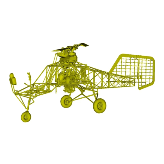
- Page 3 World's first series production helicopter. STEP-BY-STEP MODEL KIT BUILDING INSTRUCTIONS This is a Flettner Fl-282 V21 Kolibri helicopter unassembled “cutaway” model kit produced under 1/18 scale for aviation or military diorama enthousiasts & scale modelers. This kit contains all necessary parts for assembling ONE model under 1/18 scale.
- Page 4 The scale model kit contains 40 parts, 3D printed with Frosted Ultra Detail matte translucent plastic material. Please check & identify each part closely before proceeding to building process. Cyanoacrylate glue is recommended for best results.
- Page 5 This is the rotary engine part & a sprue with three small cylindrical shaped wedges. These edges should be removed from sprue carefully. Be sure you identify these parts correctly. The kit contains one (1) rotary engine & three (3) cylindrical wedges.
- Page 6 Use a modeling knife with a sharp blade and remove carefully the sprue part (marked with red colour). Due the fact that rotary engine part was produced hollowed, these three small cylindrical shaped wedges will be used as caps to close engine openings.
- Page 7 Insert the three small cylindrical shaped wedges as shown on picture. The two smaller wedges must fill the upper & lower gaps on the vertically positioned pipe and the largest of the three should close the opening in the back side of the engine part.
- Page 8 Insert the engine block carefully underneath the main tube frame and place it such way to align the engine’s four slots right onto the frame’s support beams. Use extra caution while installing the engine & avoid violent moves to prevent plastic fracture.
- Page 9 All the four slots on engine’s back side should be simultaneously aligned onto the tube frame’s support beam heads (marked with red circles). Avoid violent moves while installing engine to prevent damage of battery bracket part (marked into blue circle).
- Page 10 As soon as the four engine slots are simultaneously aligned onto the tube frame’s support beam heads, slide the engine block backwards (marked with red arrows), as shown on picture. Then, secure in place by adding a drop of cyanoacrylate super glue.
- Page 11 These parts are the transmission unit & the drive shaft. The transmission unit should be placed on the front of the engine block from which the drive shaft ran to upper gearbox. Be sure you identify the parts correctly before proceeding to the next step.
- Page 12 Insert the drive shaft part into the transmission unit’s upper opening as shown on the picture. The drive shaft designed as mirrored part and therefore can be installed either on one side or the other - no matter which side is the top and which is bottom.
- Page 13 Insert the block carefully underneath the main tube frame and place it such way to align transmission’s rear opening against the engine’s front end. Use extra caution while installing the transmission & avoid violent moves to prevent damage on plastic.
- Page 14 As soon as the transmission block’s rear opening is aligned right onto the engine’s front end, slide the transmission block backwards (marked with red arrow), as shown on picture to fit. Then, secure in place by adding a drop of cyanoacrylate super glue.
- Page 15 This is the engine’s cooling propeler fan. The twin blade propeler part should be placed on the front end of the previously installed transmission block. Be sure you identify the part correctly. The kit contains one (1) cooling twin blade propeler fan.
- Page 16 This is how the assembled block of rotary engine, transmission unit, drive shaft & cooling twin blade propeler fan should look like when correctly fit into each other. Notice that the helicopter’s tubular frame isn’t visible here for better example view.
- Page 17 These are the crew seat perforated plates for pilot & observer. Be sure you identify these parts correctly. The kit contains three (3) crew seat perforated plates. Keep in mind that the front (pilot’s) seat consist by one part only - the lower seat plate part...
- Page 18 Install each crew seat part properly on frame rails as shown on picture above. Keep in mind that pilot’s front seat consist by lower part only since pilot use parachute as seat back pillow. On the other hand, observer’s rear seat consists of two parts.
- Page 19 These parts are the tail rudder fin and the rudder fin servo bars. On real Flettner FL-282 kolibri helicopter, the tail rudder fin was made of doped fabric covering over tail frame made by wood. The kit contains one (1) tail rudder fin & two (2) servo bars.
- Page 20 Align the tail rudder fin’s slots onto rear side fuselage section & attach the part to vertical stabilizer hinges, as shown on the above picture. Try dry fit testing before the final gluing & use cyanoacrylate super glue for best results to secure in place.
- Page 21 Align the rudder fin servo bars with rudder fin and carefully insert the forks onto the rudder control cranks as required. Notice that if rudder fin is tilted (max 40° deflection), the rudder pedals & nose wheel should be also positioned accordingly.
- Page 22 This is how the installed tail rudder fin & servo bars on each side should look like when correctly installed on vertical stabilizer. Notice that rudder fin can be glued in neutral position or tilted with max 40° deflection & each servobar set accordingly.
- Page 23 Install the two horizontial elevator fins by inserting the pins through rear fuselage section frame openings as shown on the picture. Notice that if the elevator fins are set tilted or neutral the pilot’s control stick should be also positioned accordingly.
- Page 24 This is the upper gearbox unit which connects the two rotor shafts. It is installed on upper frame & linked with engine’s transmission drive shaft. Be sure you identify this part correctly before proceeding to next step. The kit contains one (1) upper gearbox...
- Page 25 All the four pins on gearbox unit should be simultaneously aligned onto the upper frame’s slots as shown on picture. Avoid violent moves while installing to prevent damage on plastic parts and secure in place by adding a drop of cyanoacrylate glue.
- Page 26 This is how the gearbox unit should look like when when correctly installed on upper frame & attached in place by inserting pins into frame slots (marked with red circles). Same time the unit need to be linked downwards with engine’s transmission shaft part.
- Page 27 This is a detailed view of the correctly installed gearbox unit as seen underneath the fuselage frame. Notice that the forementioned gearbox unit is linked (marked with red circle) with previously assembled engine’s transmission through a shaft coupling.
- Page 28 This is how the assembled block of rotary engine, transmission unit, cooling twin blade propeler fan, drive shaft & upper gearbox unit should look like when correctly fit into each other. Notice that tube frame is not visible here for better example view.
- Page 29 The kit contains five (5) cylindrical shaped bars of different lengths. These bars will be installed on selected points on scale model for additional detail. Use a modeling knife and remove sprue (marked with red colour) to release bars as individual pieces.
- Page 30 Align the 24mm & 23.4mm long bars (found as the first & second bars on previously mentioned sprue) & attach forks on elevator & pitch control cranks & connect the gearbox unit with servo bars linkage, as marked with red arrow on the above picture.
- Page 31 This is a detailed view of the correct attachment of the 24mm & the 23.4mm long bars (both marked with yellow colour) connecting the gearbox unit control cranks with roll & elevator control link (all cranks marked with blue color) as shown on picture...
- Page 32 Insert the 22.6mm long bar (found as the third in a row item on previously mentioned sprue) through the area between gearbox unit & rear side fuselage section as marked with red arrow on above picture, until bar’s lower fork reach on pitch control crank.
- Page 33 This is a detailed view of the correct attachment of the 22.6mm long bar (third in a row item on previously mentioned sprue) marked with yellow colour, connecting the gearbox unit control crank with pitch control linkage (both marked with blue colour)
- Page 34 At last, use the remaining 18.5mm long twin bars (fourth & fifth in a row items on the previously mentioned sprue) and install them such way to connect throttle cranks on engine with the fuel control link (both marked with blue colour) as shown on picture.
- Page 35 This is a detailed view of the correct attachment of the 18.5mm long twin bars (both marked with yellow colour) on the radial engine’s throttle cranks (both marked with blue colour) as shown on picture. The upper forks should fit on fuel control linkage.
- Page 36 This is a detailed view of the left bar correct attachment as seen from left side. As soon as the bars (marked with yellow colour) are aligned on upper & lower cranks (marked with blue colour) as shown on picture, secure with a cyanoacrylate glue drop...
- Page 37 This is a detailed view of the right bar correct attachment as seen from right side. As soon as the bars (marked with yellow colour) are aligned on upper & lower cranks (marked with blue colour) as shown on picture, secure with a cyanoacrylate glue drop...
- Page 38 These are the fixed non-retractable tricycle type undercarriage. Be sure you identify parts correctly before proceeding to next step. The kit contains four (4) parts for landing gear tubular shaped struts & one (1) central “A” shaped supporting section.
- Page 39 Align the central “A” shaped supporting section anchoring points on two fork shaped slots found on the lower fuselage area, as the red arrows indicate on picture above. Successful assembly of this central section will positively affect process to follow.
- Page 40 Due to the delicate structure & shape of landing gear, it is adviced to reinforce the tubular shaped struts. To do so, use a common stainless steel sewing needle (approx 50mm long x 1mm diameter wide) and then remove bolt & tip (marked with red colour).
- Page 41 Insert the steel pin through the hollow landing gear tubular shaped strut parts and secure in place with cyanoacrylic super glue. The metal pin should be long enough (approx 40mm) in order to protrude approx 20mm into each part of landing gear strut...
- Page 42 Notice that the upper & lower anchoring points on each tubular landing gear strut end should be simultaneously aligned onto the tube frame’s fork shaped slot (marked with red arrows). Avoid any violent move while installing the strut to prevent damage...
- Page 43 This is how the fixed non-retractable tricycle type undercarriage frame should look like when the parts correctly installed on the fuselage frame. Notice the details marked into the red circles. Secure in place with a drop of cyanoacrylate super glue.
- Page 44 These are the fixed non-retractable tricycle type undercarriage wheels. Be sure you identify parts correctly before proceeding to next step. The kit contains one (1) nose gear 350x150 mm size & two (2) main 465x165 mm size wheels. All wheels are hollow.
- Page 45 Attach the two (2) main landing gear wheels to the non-retractable tricycle type undercarriage, as shown by the above picture. Avoid violent moves while installing the wheels on landing gear legs and use cyanoacrylate super glue for best results.
- Page 46 This is the “U” shaped nose wheel fork of the braced fixed landing gear with shock absorber leg coupled with rudder pedals for steering. Be sure you identify the part correctly before proceeding next step. The kit contains one (1) “U” shaped nose fork.
- Page 47 Insert the “U” shaped nose wheel supporting fork pin into the shock absorber slot as shown on the above picture and make sure that axes are aligned. Notice that if the nose wheel is tilted, the rudder fin and pedals should be also positioned accordingly...
- Page 48 From left to right, these parts are fuel cocking lever, kg-12a cyclic control stick & rudder pedals. Be sure you identify these parts correctly before proceeding to next step. The kit contains one (1) fuel cocking lever, one (1) cyclic & one (1) pedals part.
- Page 49 Insert the kg-12a cyclic control stick part on the proper slot just in front of the pilot’s seat and Attach the rudder foot pedals part on forward framework, as shown on the above picture. Notice that the round side of pedals part should face forward.
- Page 50 The fuel cocking lever should be pluged slightly tilted upwards at approximately 30 degrees angle in relative to horizon line, into the fork shaped slot found right of the pilot seat as shown in the picture. Secure in place with cyanoacrylate super glue.
- Page 51 These parts are the front instruments panel receiver and the gauges dashboard. Be sure you identify these parts correctly before proceeding to next step. The kit contains one (1) front instruments panel receiver and one (1) gauges dashboard part.
- Page 52 Cut a clear plastic part (marked with light blue colour) according to the dashboard shape & place it as shown on picture to simulate glass. Adding decal is recommended. Clear part isn’t included into kit since 3d printer cannot produce transparent parts.
- Page 53 Attach the assembled instrument dashboard & receiver onto front fuselage frame by plugging the pins properly into the fork shaped slots found in front of the rudder pedals as shown in the above picture. Secure in place with cyanoacrylate super glue.
- Page 54 Notice the details marked into the red circle. This is how the lower part of the instrument panel receiver should look like when correctly installed on the front cockpit area framework. As shown in picture above, rudder pedals are not obstructed...
- Page 55 These are the helicopter’s rotor heads & their extension hollow tubes (32.5mm long & 1mm internal diameter wide each). Be sure you identify these parts correctly before proceeding to next step. The kit contains two (2) rotor heads & four (4) hollow tubes.
- Page 56 Due to the delicate structure & shape of rotor heads, it is adviced to reinforce the extension hollow tubes. To do so, use a common stainless steel sewing needle (approx 50mm long x 1mm diameter wide) and then remove bolt and tip (marked with red colour)
- Page 57 Insert the steel pin through the 32.5mm long hollow plastic tube and pass to other end. The metal pin should be sufficiently longer (approx 50mm is ok) than plastic tube in order to protrude approximately 8 to 10mm from each side of hollow plastic tubes...
- Page 58 Insert the stainless steel pin & plastic tube through the slot of the rotor head. Repeat reinforcment process for all the remaining hollow plastic tubes and attach on both sides of the two rotor heads. Secure in place with cyanoacrylate super glue.
- Page 59 The kit contains four (4) rotor blades. Attach each one of the rotor blades onto rotor heads by inserting the metal pins into the proper 1mm wide slots found on each rotor blade as shown in above picture. Secure in place with cyanoacrylate super glue...
- Page 60 Keep in mind that the right rotor rotates clockwise direction and the left rotor rotates counter clockwise direction (as seen from above helicopter). Pay attention to the correct pitch orientation and how the rotor blades are attached on rotor heads.
- Page 61 Install the rotor heads & blades to the upper gearbox unit’s rotor shafts as shown in above picture. Attaching one rotor head & blades first and then placing the other with a 90 degrees rotating phase difference, will make assembly process much easier.
- Page 62 As described before, installing one rotor head & blades first and then placing the other with a 90 degrees rotating phase difference, will lead to much easier assembly process. This is how rotor heads & blades should look like when correctly installed.
- Page 63 The two counter-rotating 2-blade rotors were synchronized to be parallel in the 45 degrees angle possition. This is how they should look like when seen from above. Notice that right rotor rotates clockwise and left rotor counter clockwise direction...
- Page 64 All three wheels are made hollow & are designed in such a way to be slightly flatten on lower side to simulate the helicopter’s weight. Each tire has a 4mm wide hole so that a pin can be inserted later to keep model secured on diorama base (recommended)
- Page 65 Model mounting on diorama base with pins through hollow tires is also recommended to evenly distribute weight & not structurally stress the central “A” shaped section of the landing gear & anchoring points & to avoid possibility of collapse or breakage...
- Page 66 Additional scale models & diorama scene accessories such as fuel canisters, oil barrels, wheel chokes, maintenance ladders, fire extinguishers, hydraulic hoists etc (not included into this kit) are available for sale by “anyuta 3d print creations” shop.
- Page 67 21.7mm 15.8mm 19.6mm 4.4mm Center instruments dashboard & right auxiliary console dimensions for decals: Center dashboard 21.7x19.6mm & right auxiliary console 15.8x4.4mm. By scaling to aforementioned sizes & printing, can be placed behind the bezels to replicate gauges.
Need help?
Do you have a question about the FLETTNER FL-282 V21 KOLIBRI and is the answer not in the manual?
Questions and answers