
Related Manuals for Mecal CDA10

Summary of Contents for Mecal CDA10
- Page 1 TRASLATION OF ORIGINAL INSTRUCTIONS CRIMP DATA ANALYZER CDA10 USE AND MAINTENANCE MANUAL Model: CDA10 Customer: Serial number: Year of manufacturer: 2019 Revision: 01...
- Page 4 Distributing and/or duplicating this manual in any form, whole or partially, without written authorisation from Mecal S.r.l. is prohibited. Mecal S.r.l. reserves the right to modify the characteristics of the product described in this manual without notice. In case of doubts or difficulties in understanding or interpreting this manual, the original/official version indicated as "ORIGINAL INSTRUCTIONS"...
- Page 5 CRIMP DATA ANALYZER CDA10 STRUCTURE OF THE MANUAL The manual is divided into 9 chapters, the last of are the attachments. CHAPTER 1 - GENERAL INFORMATION This chapter contains general descriptions regarding the structure of the manual. CHAPTER 2 - SAFETY...
-
Page 6: Table Of Contents
CRIMP DATA ANALYZER CDA10 CONTENTS 1. GENERAL INFORMATION ........................10 1.1 INTRODUCTION ............................10 1.2 SUPPORT ..............................10 1.3 GLOSSARY ..............................11 1.4 SIMBOLS ..............................13 1.5 MANUFACTURER’S INFORMATION ......................14 1.6 SAFETY STANDARDS ..........................15 1.7 MANUFACTURER’S RESPONSIBILITIES ...................... 15 1.8 MACHINE MANAGEMENT ......................... - Page 7 5.2.2 Connecting to electrical mains on P040 presses................55 5.2.3 Connecting to electrical mains on P080 and P120 presses ............... 56 5.2.4 Replacing the force cell TT1000 with CDA10 ..................57 5.2.5 Auxiliary connecting ........................... 58 5.3 CHECKS AND VERIFICATIONS ........................59 5.3.1 General checks on the mechanical units ...................
- Page 8 CRIMP DATA ANALYZER CDA10 6.3 CONTROL AND SENSOR SYSTEMS ......................68 6.4 MACHINE ARRANGEMENT ........................69 6.4.1 Encoder configuration ........................69 6.4.2 Acoustic signal setting ........................70 6.4.3 Web connection ..........................71 6.4.4 Network setting ..........................73 6.4.5 Software update ..........................74 6.4.6 Sensor calibration ..........................
- Page 9 CRIMP DATA ANALYZER CDA10 8.3 SAFETY CONTROL PLAN ........................... 107 8.3.1 Functional checks and tests on safety devices ................107 8.4 MACHINE STOP PROCEDURE ........................108 8.5 MAINTENANCE SHEETS ........................... 109 8.6 SPARE PARTS ............................111 8.6.1 Mechanical spare parts ........................111 8.6.2 Electrical spare parts ........................
-
Page 10: General Information
CRIMP DATA ANALYZER CDA10 GENERAL INFORMATION SAFETY GENERAL DESCRIPTION PACKAGING AND TRANSPORT INSTALLATION DISMANTLING MAINTENANCE ATTACHMENTS REV.01... - Page 11 CRIMP DATA ANALYZER CDA10 REV.01...
-
Page 12: Introduction
CRIMP DATA ANALYZER CDA10 1. GENERAL INFORMATION 1.1 INTRODUCTION Mecal S.r.l., manufacturer of the equipment in question, will hereafter be referred to as “Manufacturer”. The company that purchased the equipment will hereinafter be referred to as "Client". This manual contains all the information necessary for correct installation, regular use and suitable maintenance of the machine. -
Page 13: Glossary
CRIMP DATA ANALYZER CDA10 1.3 GLOSSARY Component: constitutive part of the electrical equipment, usually specified by its function, but used in various applications. Contact: person responsible for conducting certain operations or assessments that may occur during work or maintenance. Control circuit (of a machine): circuit used to control the operation of the machine and for protecting power circuits. - Page 14 CRIMP DATA ANALYZER CDA10 Protective device: means of protection other than a guard. Protective means: guard or protection device. Qualified personnel or qualified maintenance personnel: those persons who have attended specialisation courses, training, etc. and have experience in the installation, commissioning and maintenance, repair, transport and handling of the machine.
- Page 15 CRIMP DATA ANALYZER CDA10 1.4 SYMBOLS The manual uses some symbols that are intended to draw the attention of the reader and highlight some particularly important aspects. SYMBOL MEANING NOTE Indicates a hazard with risk of injury or even death for the user.
- Page 16 CRIMP DATA ANALYZER CDA10 1.5 MANUFACTURER CONTACTS The Manufacturer's Technical Department is always available to Clients for any type of information or clarification concerning use, maintenance, installation, etc. The latter should always put the questions in clear terms, with references to this manual, always indicating the data shown on the identification plate of the machine in question.
-
Page 17: Safety Standards
CRIMP DATA ANALYZER CDA10 1.6 SAFETY STANDARDS The requirements, indications, standards and related safety notes described in the various chapters of the manual are intended to define a series of behaviours and obligations which must be followed when performing the various activities that constitute the intended use of the machine, aimed at operations that are safe for personnel, equipment and the surrounding environment. -
Page 18: Machine Management
(signs or traces of impact) as follows: • With a written note on the Transport Document. • Communicating the damage detected by registered letter to the carrier and to Mecal S.r.l., within 48 hours of receipt of the machine. -
Page 19: Warranty
1.10 WARRANTY Mecal S.r.l. guarantees that its machines are free from manufacturing defects for the period of time indicated in the stipulated contractual conditions. The purchaser is only entitled to the replacement of parts recognised as defective: the costs of packaging and transport, as well as any installation, are at the purchaser’s expense. - Page 20 CRIMP DATA ANALYZER CDA10 REV.01...
-
Page 21: Safety
CRIMP DATA ANALYZER CDA10 GENERAL INFORMATION SAFETY GENERAL DESCRIPTION PACKAGING AND TRANSPORT INSTALLATION DISMANTLING MAINTENANCE ATTACHMENTS REV.01... - Page 22 CRIMP DATA ANALYZER CDA10 REV.01...
- Page 23 CRIMP DATA ANALYZER CDA10 2. SAFETY 2.1 GENERAL INFORMATION The Customer must instruct personnel regarding the risks of injury, the safety devices installed on the machine and the general accident prevention rules provided for by European Community directives and by legislation in the country where the machine is installed.
-
Page 24: Machine Certification
CRIMP DATA ANALYZER CDA10 2.1.1 MACHINE CERTIFICATION The machine is supplied with an EC Declaration of Conformity with the essential safety requirements in accordance with Machinery Directive 2006/42/EC (Annex II A) and Electromagnetic Compatibility Directive 2014/30/EU. REV.01... -
Page 25: Intended And Improper Uses
CRIMP DATA ANALYZER CDA10 2.1.2 INTENDED AND IMPROPER USES The CDA10, combined with the press, has been designed and built to compare the force curves of crimping with reference curves and to check the quality of the work. Operating specifications: Range 0 –... -
Page 26: Environmental Operating Conditions
CRIMP DATA ANALYZER CDA10 2.2 ENVIRONMENTAL OPERATING CONDITIONS The area where the machine is located must be a covered environment equipped with all the safety arrangements deriving from the laws in force in the user country. 2.2.1 FIRE PROTECTION INSTALLATION The machine is not equipped with its own fire protection system. -
Page 27: Vibrations
CRIMP DATA ANALYZER CDA10 2.2.5 VIBRATIONS The equipment does not produce vibrations that are dangerous for the health of personnel working. CAUTION Excessive vibrations can only be caused by a mechanical failure, which must be immediately reported and eliminated. 2.2.6 NOISE The equipment does not produce noise that are dangerous for the health of personnel working. -
Page 28: Disposal Of Exhausted Materials
CRIMP DATA ANALYZER CDA10 2.3 DISPOSAL OF EXHAUSTED MATERIALS In its normal operation, the machine does not produce any kind of waste or exhausted material. There are specific regulations for environmental protection in every country with relation to the disposal of such materials. -
Page 29: Residual Risks
CRIMP DATA ANALYZER CDA10 2.6 RESIDUAL RISKS 2.6.1 GENERAL INFORMATION All the areas and the parts at risk were evaluated during the design phase, and thus all the precautions necessary to avoid risks to people and damage to machine components have been taken. -
Page 30: Plates Present On The Machine
CRIMP DATA ANALYZER CDA10 2.6.3 PLATES PRESENT ON THE MACHINE The Manufacturer has installed a series of monitoring plates on the equipment, defined in accordance with European legislation regarding the graphic symbols to be used. The plates in question are in a clearly visible position on the machine. - Page 31 CRIMP DATA ANALYZER CDA10 REV.01...
-
Page 32: General Description
CRIMP DATA ANALYZER CDA10 GENERAL INFORMATION SAFETY GENERAL DESCRIPTION PACKAGING AND TRANSPORT INSTALLATION DISMANTLING MAINTENANCE ATTACHMENTS REV.01... - Page 33 CRIMP DATA ANALYZER CDA10 REV.01...
-
Page 34: Layout
CRIMP DATA ANALYZER CDA10 3. GENERAL DESCRIPTION The control unit detects and analyses the force profile obtained by crimping. profile compared with a previously learned one and, in the event of defective crimping, the unit emits a signal to the press that disables the operating mode. - Page 35 CRIMP DATA ANALYZER CDA10 Installation on P040 and P080 presses. Installation on TT and P107 presses. REV.01...
- Page 36 CRIMP DATA ANALYZER CDA10 REV.01...
- Page 37 CRIMP DATA ANALYZER CDA10 3.2 TECHNICAL FEATURES The following table shows the main technical features of the machine. GENERAL TECHNICAL FEATURES Measuring range 0 – 20 kN Resolution 10 Newtons Repeatability 0,1 % Sensor type Piezo-ceramic Power supply (from the press) 9 –...
-
Page 38: Description Of Units
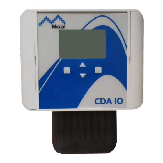
CRIMP DATA ANALYZER CDA10 3.3 DESCRIPTION OF UNITS 3.3.1 ADJUSTABLE SUPPORT The bracket is fixed to the press frame. Controller inclination can be regulated using the knob. 3.3.2 CONTROL UNIT Equipped with a display to show the force curve of the crimping and four front buttons for choosing the settings and for performing configuration. -
Page 39: Force Cell Sensor
CRIMP DATA ANALYZER CDA10 3.3.3 FORCE CELL SENSOR piezoelectric sensor converts the force applied by the press in an electrical signal which is read and monitored by the control unit. On model TT and P107 presses, the cell sensor (C) -
Page 40: Encoder
CRIMP DATA ANALYZER CDA10 3.3.4 ENCODER The optical and incremental encoder communicates the direction, speed and position of the press in operation to the control unit. The control unit does not intervene if the encoder is accidentally disconnected, as it does not detect machine activity and cannot report a malfunction. - Page 41 CRIMP DATA ANALYZER CDA10 REV.01...
- Page 42 CRIMP DATA ANALYZER CDA10 GENERAL INFORMATION SAFETY GENERAL DESCRIPTION PACKAGING AND TRANSPORT INSTALLATION DISMANTLING MAINTENANCE ATTACHMENTS REV.01...
- Page 43 CRIMP DATA ANALYZER CDA10 REV.01...
-
Page 44: Packaging
CRIMP DATA ANALYZER CDA10 4. PACKAGING AND TRANSPORT 4.1 PACKAGING The packaging does not protect from external weather events such as rain, snow, hail, etc., even when the components are packed and transported in wooden crates. For this reason, if packaging remains exposed to the elements, it is essential that they remain in closed containers until they are finally stored. -
Page 45: Trasport
CRIMP DATA ANALYZER CDA10 4.2 TRASPORT Depending on the destination, the machine can be shipped in the following ways: • BY SEA → the various parts that make up the machine are enclosed in flat bottomed crates and anchored with tie rods. The crates are lined and have a door for customs checks. They also contain bags with desiccant salts against moisture and sea salt. -
Page 46: Lifting And Handling
CRIMP DATA ANALYZER CDA10 4.3 LIFTING AND HANDLING You must know the weight of the machine before performing any handling and/or lifting.. CAUTION All handling and/or lifting operations must be carried out by qualified personnel, aware of the standards regarding the lifting and handling of loads, and in full compliance with them. -
Page 47: Weight Of Packages
CRIMP DATA ANALYZER CDA10 4.3.1 WEIGHT OF PACKAGES Description Weight Complete equipment Adjustable support Controller Force cell sensor Encoder REV.01... - Page 48 CRIMP DATA ANALYZER CDA10 REV.01...
-
Page 49: Installation
CRIMP DATA ANALYZER CDA10 GENERAL INFORMATION SAFETY GENERAL DESCRIPTION PACKAGING AND TRANSPORT INSTALLATION DISMANTLING MAINTENANCE ATTACHMENTS REV.01... - Page 50 CRIMP DATA ANALYZER CDA10 REV.01...
-
Page 51: General Safety Precautions
CRIMP DATA ANALYZER CDA10 5. INSTALLATION Before installing the equipment: • Remove the protective packaging of the various parts that make up the equipment; • Remove any fasteners used for transportation. 5.1 EQUIPMENT INSTALLATION 5.1.1 GENERAL SAFETY PRECAUTIONS The operations described in this paragraph must be performed by authorised personnel. -
Page 52: Choosing The Site And Verifying Installation Requirements
CRIMP DATA ANALYZER CDA10 5.1.2 CHOOSING THE SITE AND VERIFYING INSTALLATION REQUIREMENTS The customer MUST prepare: • A sufficiently large room, free from obstacles, equipped according to the safety regulations in force in the user country. • Proper ventilation and lighting. -
Page 53: Positioning And Assembling The Force Cell Sensor On Tt And P107 Presses
CRIMP DATA ANALYZER CDA10 5.1.4 POSITIONING AND ASSEMBLING THE FORCE CELL SENSOR ON TT AND P107 PRESSES Follow the procedure below to install the load cell on press models TT and P107: • Fit the T-connector support (A) with the two hex socket head cap screws (N) on the press slide;... -
Page 54: Positioning And Assembling The Force Cell Sensor On P040 And P080 Presses
CRIMP DATA ANALYZER CDA10 5.1.5 POSITIONING AND ASSEMBLING THE FORCE CELL SENSOR ON P040 AND P080 PRESSES Follow the procedure below to install the load cell on press models P040 and P080: • Insert the load cell sensor (C) between the press slide and the shank connection (Q);... -
Page 55: Positioning And Assembling The Encoder
CRIMP DATA ANALYZER CDA10 5.1.6 POSITIONING AND ASSEMBLING THE ENCODER Proceed as follows to install the encoder unit: • Tighten the headless screw, or grub screw (T), on the encoder control shaft (U); • Tighten the hub (U) at the end of the output shaft (S) from the gear motor, on the grub screw (T) that has just been inserted;... -
Page 56: Connections
CRIMP DATA ANALYZER CDA10 5.2 CONNECTIONS The machine must have the following connections: • Electrical HAZARD Machine power supply connection operations must be carried out solely by specialised personnel and are subject to use of personal protective equipment. 5.2.1 CONNECTING TO THE ELECTRICAL MAINS ON TT AND P107 PRESSES 5.2.1.1 STANDARD... - Page 57 CRIMP DATA ANALYZER CDA10 5.2.1.2 STANDARD The operations to be carried out to connect the load cell electrically are: • Check that the switch, located on the press or in the electrical cabinet/panel, is in the OFF (O) position. • Disconnect the press from the electrical mains.
-
Page 58: Connecting To Electrical Mains On P040 Presses
CRIMP DATA ANALYZER CDA10 5.2.2 CONNECTING TO THE ELECTRICAL MAINS ON P040 PRESSES The operations to be carried out to connect the load cell electrically are: • Check that the switch, located on the press or in the electrical cabinet/panel, is in the OFF (O) position;... - Page 59 CRIMP DATA ANALYZER CDA10 • Eliminate clamp by the green cable and connect it to the pos.6 input on the terminal board [located on the right side, seen from the rear, in the electrical box of the press]; • Close...
-
Page 60: Replacing The Force Cell Tt1000 With Cda10
5.2.4 REPLACING THE FORCE CELL TT1000 WITH CDA10 The operations to be carried out to replace load cell TT1000 with load cell CDA10 are: • Check that the switch, located on the press or in the electrical cabinet/panel, is in the OFF (O) position;... -
Page 61: Auxiliary Connecting
Follow the connection and installation instructions present in the manual of the equipment to be connected to the CDA10. If the equipment is not produced by Mecal S.r.l., contact the manufacturer of the device and follow the wiring diagram to the relays above. -
Page 62: Checks And Verifications
CRIMP DATA ANALYZER CDA10 5.3 CHECKS AND VERIFICATIONS Before starting the machine, carry out a series of checks and verifications in order to avoid problems during its operation. CAUTION Before making any movement, make sure that there are no faults in order to avoid damage to the machine. -
Page 63: Electrical System Check
CRIMP DATA ANALYZER CDA10 5.3.2 ELECTRICAL SYSTEM CHECKS 1. Check the electrical system in general and, in particular, check that all the cables inside the electronic boards are correctly connected [see the relative electrical diagrams]. 2. Check that the connector interfacing with the machine is correctly connected to the sensing unit. -
Page 64: Universal International Recycling Codes
CRIMP DATA ANALYZER CDA10 5.4 UNIVERSAL INTERNATIONAL RECYCLING CODES FOLLOWING INSTALLATION Following the removal of machine packaging and its installation, remove the packaging from the area surrounding the machine and dispose of it in accordance with the regulations in force. The international recycling codes are indicated below. - Page 65 CRIMP DATA ANALYZER CDA10 REV.01...
- Page 66 CRIMP DATA ANALYZER CDA10 REV.01...
- Page 67 CRIMP DATA ANALYZER CDA10 REV.01...
-
Page 68: Use
CRIMP DATA ANALYZER CDA10 GENERAL INFORMATION SAFETY GENERAL DESCRIPTION PACKAGING AND TRANSPORT INSTALLATION DISMANTLING MAINTENANCE ATTACHMENTS REV.01... - Page 69 CRIMP DATA ANALYZER CDA10 REV.01...
-
Page 70: Switch
CRIMP DATA ANALYZER CDA10 6. USE 6.1 SWITCH The equipment is dependent on the machine; therefore, it is necessary to use the press switch to operate or switch off both. The switch has two positions: • OFF position (O), in which the power supply is disconnected •... -
Page 71: Control And Sensor Systems
CRIMP DATA ANALYZER CDA10 6.3 CONTROL AND SENSOR SYSTEMS Below is the location of the control systems and of the sensors that are part of the equipment: • Sensing and control unit Equipped with a display to show the force curve... - Page 72 CRIMP DATA ANALYZER CDA10 6.4 MACHINE ARRANGEMENT 6.4.1 ENCODER CONFIGURATION When the encoder is disconnected from the control unit, it emits an acoustic and visual signal. You must therefore make sure that the encoder connector is correctly connected to the control unit.
-
Page 73: Acoustic Signal Setting
CRIMP DATA ANALYZER CDA10 4. The "Encoder" item shows the real time value of the encoder angle. With the press in stand-by [P.M.S.], turn the encoder until an angle between 350,00° and 355,00° is set (to avoid conflicts with "disconnected” Encoder status, do not set the angle to 0,00°... -
Page 74: Web Connection
CRIMP DATA ANALYZER CDA10 6.4.3 WEB CONNECTION The control unit is equipped with a web server, which provides a network connection to operational activities. It is possible to connect the unit to a network switch or directly to the Ethernet port of a PC;... - Page 75 CRIMP DATA ANALYZER CDA10 If the connection fails, check that the controller's network interface has the IP address set and that it is in the same subnet as the PC and or server. Also check if your PC or server functions as a DHCP server.
-
Page 76: Network Setting
CRIMP DATA ANALYZER CDA10 6.4.4 NETWORK SETTING Click on "Network” on the sidebar of the main web page to enter the "Network Settings" menu. The "Network Settings" web page lets you modify the IP address parameters, the same ones that can be configured by the control unit and which are described in paragraph 6.4.3. -
Page 77: Software Update
CRIMP DATA ANALYZER CDA10 6.4.5 SOFTWARE UPDATE Make sure that the operating software is up to date with the latest version available, as the manufacturer may have issued a new release in order to fix bugs or add new features. - Page 78 CRIMP DATA ANALYZER CDA10 2. Click on “Choose file”, select the file from the desired folder and then click on “Upload”. It takes a few seconds to transmit the file and restart the device to install the new software. During this time, the backlight on the controller screen flashes.
- Page 79 CRIMP DATA ANALYZER CDA10 6.4.6 PEAK FORCE CALIBRATION The control unit makes its decisions (Pass/Fail) by comparing the reference force curve profile, detected during the learning process, with the profile of the force curve of each crimp. For this reason, the load cell must not be calibrated, but must only be repeatable.
-
Page 80: Crimp Force Detection History
CRIMP DATA ANALYZER CDA10 formula: For example: If the display shows a peak force of 10kN but you want a displayed value of 8kN, change the transducer capacity value as follows: 3162 * 8 / 10 = 2530 It is also possible to view or edit the calibration notes. - Page 81 CRIMP DATA ANALYZER CDA10 These values can be used for service requests and/or to establish a service program dedicated to the machine. The counters can be reset or adjusted, but an authorisation code must be provided. Furthermore, the data can be displayed graphically by clicking on the "History Plot"...
-
Page 82: Operating Password Setting
CRIMP DATA ANALYZER CDA10 6.4.8 OPERATING PASSWORD SETTING An operating password can be set to prevent changes to the control unit settings. password protection and the password to install the software update are disabled by default. Follow these steps to set the password: 1. -
Page 83: Machine Use Procedures
CRIMP DATA ANALYZER CDA10 6.5 MACHINE USE PROCEDURES 6.5.1 INITIAL CHECKS The operator must check the following before starting the machine: • Make sure that all power sources are properly connected to the respective power supply networks. • Make sure that there are no foreign bodies in the radius of action of the machine. -
Page 84: Use
CRIMP DATA ANALYZER CDA10 6.6 USE 6.6.1 LEARNING The control unit signals correct or incorrect crimping, comparing the force curve profile with a reference force curve that records during the learning phase. In the learning phase, the press, the applicator and any accessories must be installed as in production. - Page 85 CRIMP DATA ANALYZER CDA10 3. Sequence of learning steps: three crimpings. See paragraph 6.6.5 to set the parameters for evaluating the force curves. REV.01...
-
Page 86: Production
CRIMP DATA ANALYZER CDA10 6.6.2 PRODUCTION The main screen on the control unit display shows the force and reference curves. The parameters shown are as follows: CORRECT crimping (since last learning) INCORRECT crimping (since last learning) 16.7kN=OK Applied force measured and result [OK/NO]... -
Page 87: How Crimp Force Curve Mismatch Is Calculated
CRIMP DATA ANALYZER CDA10 6.6.3 HOW CRIMP FORCE MISMATCH IS CALCULATED The figure below shows a reference curve (in red) and a superimposed force curve for comparison (blue). In this example, the blue curve could be typically associated with a crimping error on insulation. - Page 88 CRIMP DATA ANALYZER CDA10 The figure below shows the reference area, which is measured and used as a divider in calculation of the non-correspondence. This helps to "normalise" the variation calculation, so that the result for incorrect crimping on a large terminal is similar to the result for incorrect crimping on a small terminal.
-
Page 89: Crimp Fail
CRIMP DATA ANALYZER CDA10 6.6.4 CRIMP FAIL The main screen on the control unit display shows the crimping error. 1. Press any button to return to the production screen. 2. Press the right [More] button to display additional information on the incorrect crimping. -
Page 90: Parameters Setting (Analysis Menu)
CRIMP DATA ANALYZER CDA10 6.6.5 PARAMETERS SETTING (ANALYSIS MENU) From the "Analysis" menu, you can set the tolerance for the non-correspondence value. The higher the number set, the less sensitive the correspondence evaluation will be. Menu → Setup → Analysis •... - Page 91 CRIMP DATA ANALYZER CDA10 To test sensitivity, it is advisable to start creating large crimping errors, moving toward the creation of smaller and smaller faults, or temporarily disabling the Drift compensation function. The value is set to YES (function enabled) or NO (function disabled). The default value is set to YES.
-
Page 92: Error Messages
CRIMP DATA ANALYZER CDA10 6.6.6 ERROR MESSAGES MESSAGGIO SPIEGAZIONE SOLUZIONE Eseguire la procedura di I valori di adattamento della curva di apprendimento. Si consiglia Drift Fail forza (Drift Compensation) vanno al di di effettuare nuovamente i fuori dell’intervallo accettabile. controlli su altezza di crimpatura e sfilamenti. -
Page 93: Unloading The Machine
CRIMP DATA ANALYZER CDA10 6.7 UNLOADING THE MACHINE CAUTION Before making any movement, be sure to switch off the machine. See the paragraph dedicated to switching off the machine for information. 6.7.1 DISCARDED CABLE UNLOADING PROCEDURE There are no procedures required for unloading the equipment. -
Page 94: Faults
CRIMP DATA ANALYZER CDA10 6.8 FAULTS PROBLEM CAUSE SOLUTION Power supply not connected to the Connect the power supply mains. to the mains. The machine and the equipment does not start. Move the switch to the ON Switch set to OFF position (O). - Page 95 CRIMP DATA ANALYZER CDA10 REV.01...
-
Page 96: Dismantling
CRIMP DATA ANALYZER CDA10 GENERAL INFORMATION SAFETY GENERAL DESCRIPTION PACKAGING AND TRANSPORT INSTALLATION DISMANTLING MAINTENANCE ATTACHMENTS REV.01... - Page 97 CRIMP DATA ANALYZER CDA10 7. DISMANTLING The following paragraph contains some recommendations and indications to correctly carry out the operations for decommissioning, dismantling and removal of the equipment at the end of its operating life. ADDITIONAL INFORMATION The operations described below are the sole responsibility of authorised personnel.
-
Page 98: Disposal
CRIMP DATA ANALYZER CDA10 NOTE If difficulty arises in disassembly, demolition and dismantling of the machine or for greater safety, contact the Manufacturer and indicate the cause of the removal and the serial number of the equipment. • The machine is built with different recyclable or non-recyclable materials. For this reason, its removal involves careful separation of the materials: glass, steel, aluminium, copper, bronze, special alloy, plastic, etc. - Page 99 CRIMP DATA ANALYZER CDA10 REV.01...
-
Page 100: Maintenance
CRIMP DATA ANALYZER CDA10 GENERAL INFORMATION SAFETY GENERAL DESCRIPTION PACKAGING AND TRANSPORT INSTALLATION DISMANTLING MAINTENANCE ATTACHMENTS REV.01... - Page 101 CRIMP DATA ANALYZER CDA10 REV.01...
-
Page 102: General Safety Precautions
CRIMP DATA ANALYZER CDA10 8. MAINTENANCE 8.1 GENERAL SAFETY PRECAUTIONS Maintenance, troubleshooting and repair operations are only allowed to be performed by authorised personnel. Personnel in charge of machine operation and maintenance must be properly trained and have in- depth knowledge of accident prevention regulations. Unauthorised personnel must remain outside the work area during operations. -
Page 103: General Hazard Notes
CRIMP DATA ANALYZER CDA10 8.1.1 GENERAL HAZARD NOTES • High voltages can cause death on contact. Always operate with the utmost caution and according to the accident prevention regulations in force in the country. • There are moving parts on the machine when it is running which can cause serious damage to people. -
Page 104: General Warnings
CRIMP DATA ANALYZER CDA10 • • Before making connections, carefully inspect all the connections and make sure there are no dirt or defects on the threading. • Before applying pressure to the systems following a repair, verify the correct tightness of connections and joints. - Page 105 CRIMP DATA ANALYZER CDA10 • The lubricants used must have good emulsion stability and be unalterable by ageing. • It is absolutely necessary to continue to use the lubricants used when filling for the first time. • Upon completion of the traditional maintenance activities shown on the sheets, technical...
-
Page 106: Qualification Of Maintenance Personnel
CRIMP DATA ANALYZER CDA10 8.2 QUALIFICATION OF MAINTENANCE PERSONNEL CAUTION The safety manager shall ensure that all the people working on the machine have received all the instructions concerning their task contained in this manual, including the initial installation and commissioning operations. - Page 107 CRIMP DATA ANALYZER CDA10 Machine manager Typical activities: Quality control and maintenance on part handling systems, in particular: • Use and evaluation of diagnostic system results; • Use of the machine in its normal operating conditions and restoration of operation after the emergency stop switch has tripped;...
- Page 108 CRIMP DATA ANALYZER CDA10 Required qualification: • Complete training as an industrial mechanic, specialising in the technical automated systems sector. • Instruction and training on the machine are ensured by the Manufacturer. Lubrication personnel Typical activities: • Regular operations to empty and fill lubricant tanks on systems;...
- Page 109 CRIMP DATA ANALYZER CDA10 • Knowledge of measurement and test methods to determine actual machine conditions. Required qualification: • Complete training as an industrial mechanic, specialising in the technical sector. Electrical/electronic maintenance personnel Typical activities: • Performing preventive maintenance, overhaul and, if necessary, repair of electrical and electronic units, in particular: ...
-
Page 110: Safety Control Plan
CRIMP DATA ANALYZER CDA10 8.3 SAFETY CONTROL PLAN CAUTION Electrically or mechanically bridging the circuit breakers on the safety circuits or tampering with them in any way is strictly prohibited. Periodically check the efficiency of the safety systems on the machine. -
Page 111: Machine Stop Procedure
CRIMP DATA ANALYZER CDA10 8.4 MACHINE STOP PROCEDURE Before carrying out the maintenance procedures described in the following chapter, the operator must stop and put the machine in maintenance status, following the procedure below: • Set the machine in optimal conditions to be able to resume operation without delays due to abnormal cycle conditions. -
Page 112: Maintenance Sheets
CRIMP DATA ANALYZER CDA10 8.5 MAINTENANCE SHEETS To guarantee the reliability of the machine, you need to ensure regular and effective maintenance and constant control of indicator instrument parameters. Maintenance, troubleshooting and repair operations are only allowed to be performed by authorised personnel. - Page 113 CRIMP DATA ANALYZER CDA10 MAINTENANCE LOG DATE OPERATOR DESCRIPTION OF INTERVENTION REV.01...
-
Page 114: Spare Parts
CRIMP DATA ANALYZER CDA10 8.6 SPARE PARTS Below is the list of components subject to wear over time (indicated with U) and those for which replacement is recommended (indicated with R). 8.6.1 MECHANICAL SPARE PARTS There are not mechanical parts subject to wear and/or recommended. - Page 115 CRIMP DATA ANALYZER CDA10 REV.01...
- Page 116 CRIMP DATA ANALYZER CDA10 GENERAL INFORMATION SAFETY GENERAL DESCRIPTION PACKAGING AND TRANSPORT INSTALLATION DISMANTLING MAINTENANCE ATTACHMENTS REV.01...
- Page 117 CRIMP DATA ANALYZER CDA10 REV.01...
-
Page 118: Attached Documentation
CRIMP DATA ANALYZER CDA10 9. ATTACHED DOCUMENTATION The following documents will be inserted at the end of this manual. N° ALLEGATO DESCRIZIONE Machine layout Exploded diagram of the machine Wiring diagram REV.01... -
Page 119: Layout
CRIMP DATA ANALYZER CDA10 9.1 MACHINE LAYOUT REV.01...
Need help?
Do you have a question about the CDA10 and is the answer not in the manual?
Questions and answers