Table of Contents
Advertisement
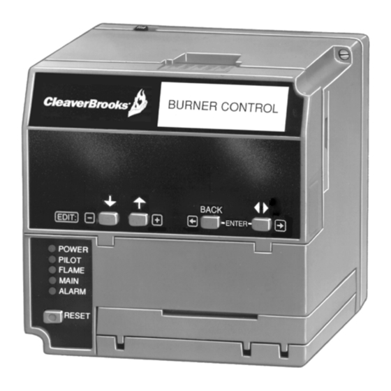
CB780E/CB784E Relay Modules
with Valve Proving
APPLICATION
The Cleaver-Brooks CB780E/CB784E (833-03517/833-
03518) is a microprocessor based integrated burner
control for automatically fired gas, oil, or combination fuel
single burner applications. The CB780E consists of a
Relay Module and Keyboard Display Module. The CB784E
consists of the Relay Module only. A subbase, Amplifier,
and Purge Card are required to complete the system.
Options include: DATA CONTROLBUS MODULE™, Remote
Display Mounting, First-Out Expanded Annunciator and
Computer Interface using Modbus™ network.
The CB780E/CB784E is programmed to provide a level of
safety, functional capability, and features beyond the
capacity of conventional controls.
CB Manual Part Number 750-234
INSTALLATION AND OPERATING INSTRUCTIONS
Functions provided by the CB780E/CB784E include
automatic burner sequencing, flame supervision, system
status indication, system or self-diagnostics, and
troubleshooting.
The CB780E/CB784E offer the Valve Proving test feature.
Using the 833-2727 Keyboard Display (standard on the
CB780E), the following features can be set-up:
• Post Purge time—Up to 60 minutes—Device shipped
with 15 seconds Post purge
• Valve Proving features include:
—
VPS test time
—
When (Never, Before, After, Split or Both)
A new 4-line LCD display option S78000A1092/U is
available to be purchased separately. Reference document
32-00154 for more information.
See the 833-2727 Instructions (750-248) for its features.
Series 5 can be programmed for ModBus communication.
At commissioning time, the Valve Proving System may be
scheduled to occur at one of five different times:
• Never—Device default as received—Valve proving
does not occur.
• Before—Valve proving before run concurrent with
Pre-Purge.
• After—Valve proving occurs after the Run state,
before the device goes to Standby (Concurrent with
Post-Purge, if selected.)
• Both—Valve proving occurs at both times Before and
After, noted above.
• Split—The main valve 2 (MV2) (high pressure) seat
test is performed at the Before time and the main
valve 1 (MV1) (low pressure) seat test is performed
during the After time.
32-00150-03
Advertisement
Table of Contents

Subscribe to Our Youtube Channel
Related Manuals for CleaverBrooks CB780E

Summary of Contents for CleaverBrooks CB780E
- Page 1 Computer Interface using Modbus™ network. • Both—Valve proving occurs at both times Before and After, noted above. The CB780E/CB784E is programmed to provide a level of safety, functional capability, and features beyond the • Split—The main valve 2 (MV2) (high pressure) seat capacity of conventional controls.
-
Page 2: Specifications
• On/Off status of all digital inputs and outputs. • Safety features: • Selected prepurge time. — Safety interlock. • Software revision and version of CB780E/CB784E and — Closed loop logic test. Keyboard Display Module. — Dynamic AMPLI-CHECK™. • Status of configuration jumpers. - Page 3 CB780E/CB784E RELAY MODULES WITH VALVE PROVING Table 1. Terminal Ratings. Terminal No. Description Ratings (120 Vac) — Flame Sensor Ground Earth G Earth Ground — L2(N) Line Voltage Common — Alarm 1A pilot duty 120 Vac (+10%/-15%), Line Voltage Supply (L1) 50 or 60 Hz (±10%).
- Page 4 CB780E/CB784E RELAY MODULES WITH VALVE PROVING Table 3. Explanation of Each Combination 4.5A ignition 180 VA ignition plus 50 VA Pilot Duty plus 2A Pilot Duty. 64 VA Pilot Duty. plus motor valve with: 4.5A ignition. motor valves with: 3850 VA...
- Page 5 833-2820 Modbus Module. 833-2732—90 sec. BURNER CONTROL (127) Edit: POWER PILOT FLAME MAIN ALARM RESET 5-1/4 (133) 5 (127) REMOVE ONLY FOR TERMINAL TEST ACCESS. M28590B Fig. 2. Mounting dimensions of CB780E/CB784E Relay Module and 833-2725 Subbase, in inches (mm). 750-234 32-00150—03...
-
Page 6: Principal Technical Features
CB780E/CB784E RELAY MODULES WITH VALVE PROVING CELL MOUNT HEAT BLOCK 1-5/8 (41) BURNER CONTROL 2-3/4 1-1/16 (27) (70) 2-3/4 (69) 1-1/4 1-1/4 (32) (32) 2 LEADS IN A Edit: 48 INCH (1.2 METER) APERTURE FLEXIBLE CONDUIT 3/4-14 3/4-14 NPSM NPSM... -
Page 7: Safety Provisions
Internal system fault. the flame detection system and amplifier 10 to 12 times 5. PILOT FLAME ESTABLISHING Period (PFEP) per minute and shuts down the CB780E/CB784E if the a. Low Fire Switch opens. detection system fails. b. Lockout Interlock opens. - Page 8 CB780E/CB784E RELAY MODULES WITH VALVE PROVING purge or opens during purge. The CB780E/CB784E will First-Out Annunciation and Self- lockout and annunciate an alarm if the switch fails to Diagnostics close within the hold time period. Sequence Status Lights (LEDs) provide positive visual...
-
Page 9: Installation
Preignition Interlock opens during STANDBY, it causes a who have jurisdiction prohibit the wiring of any hold (30 seconds). The CB780E/CB784E will lockout if the limit or operating contacts in series between the interlock does not close within 30 seconds during flame STANDBY. - Page 10 CB780E/CB784E RELAY MODULES WITH VALVE PROVING removal of the CB780E/CB784E, Expanded Annun- WARNING ciator, Keyboard Display Module, flame amplifier, flame amplifier signal voltage probes, Run/Test Switch, electrical signal voltage probes and electri- b. Keyboard Display Module—For communications cal field connections.
- Page 11 PROVIDE DISCONNECT MEANS AND OVERLOAD PROTECTION AS REQUIRED. M28586A DEDICATED DATA LINK. Fig. 7. Internal block diagram of the CB780E/CB784E (see Fig. 8–13 for detailed wiring instructions). d. Remote Reset—Use no. 22 AWG or greater MODULE™ (for remote mounting or communica- twisted pair wire, insulated for low voltage;...
- Page 12 8. Make sure loads do not exceed the terminal ratings. capable of carrying a fault current equal to the Refer to the label on the CB780E/CB784E or to the rating of the protective fuse (15A maximum, Type ratings in Specifications; see Table 1.
- Page 13 HIGH FIRE SW. LOW FIRE SW. FLAME FLAME PROVING SAFE START CHECK SIGNAL SWITCHING FIRING MOTOR ACTION RATE MOTOR NOTE: SEE APPENDIX FOR APPLICATION OPTIONS. M23946A Fig. 8. Typical wiring subbase and sequence for the CB780E/CB784E, without Valve Proving. 750-234 32-00150—03...
- Page 14 SAFE START CHECK FLAME PROVING SIGNAL SWITCHING FIRING MOTOR ACTION RATE MOTOR JR2 REMOVED FOR PILOT SEQUENCE. M24790A MV2 IS MAIN VALVE CLOSEST TO THE BURNER. Fig. 9. Typical wiring subbase and sequence for the CB780E/CB784E, with Valve Proving enabled. 32-00150—03 750-234...
- Page 15 LOCKOUT IF OFF, MV2 LEAKING (HIGH PRESSURE TEST). TEST IS RUN CONCURRENT WITH POSTPURGE, IF POSTPURGE TIME IS ENABLED. M24791A Fig. 10. CB780E/CB784E Relay Module operation, Valve Proving test options. 833-2727 KEYBOARD DISPLAY MODULE 833-2727 KEYBOARD DISPLAY MODULE (MOUNTED ON CB 780/CB 784 RELAY MODULE)
-
Page 16: Relay Module Mounting
Modules NOTE: For installation dimensions, see Fig. 2. Relay Module Mounting 1. Mount the CB780E/CB784E vertically. See Fig. 14 or mount horizontally with the knife blade terminals pointing downward. The CB780E/CB784E must be in an electrical enclosure. 2. Select the location in the electrical enclosure. Be... - Page 17 Mounting Data ControlBus™ Module 1. Align the two interlocking ears with the two mating slots on the CB780E/CB784E; see Fig. 17. Fig. 16. Keyboard Display Module installation. 2. Insert the two interlocking ears into the two mating slots and push on the lower corners of the DATA CONTROLBUS MODULE™...
-
Page 18: Installing Plug-In Flame Signal Amplifier
5. Perform all required checkout tests. Installing the Flame Detector NOTE: Table 5 lists the flame detection systems avail- able for use with the CB780E/CB784E. Make sure the correct combination of amplifier and flame detector(s) is used. Proper flame detector installation is the basis of a safe and reliable flame safeguard installation. -
Page 19: Valve Proving System
CB780E/CB784E RELAY MODULES WITH VALVE PROVING SOLID STATE SELF-CHECKING INFRARED (817-4133) ULTRAVIOLET (817-1121) BLUE WHITE ULTRAVIOLET (817-1743) BLUE WHITE BLUE YELLOW WHITE WHITE BLACK BLACK FLAME DETECTOR LEADS ARE COLOR CODED. THE BLUE LEAD MUST BE CONNECTED TO THE F TERMINAL AND THE WHITE MUST BE CONNECTED TO THE G TERMINAL. -
Page 20: Typical Valve Proving System Function
CB780E/CB784E RELAY MODULES WITH VALVE PROVING Typical Valve Proving System D. MV1 is commanded to be open while MV2 remains closed, to pressurize the space. After 4 seconds, MV1 is Function commanded closed again. Valve proving consists of monitoring the pressure in the E. - Page 21 5. Use the +/- buttons to enter the second number—8. 6. Press Enter (left/right arrow simultaneously). Edit: M22666C Fig. 26. Valve Prove time screen. This screen sets up how long the CB780E/CB784E will Edit: conduct the Valve Proving Test for a given time. VP TIme: 00:00 is shown. M22764C Fig.
- Page 22 M22668A Fig. 29. Setting Postpurge time. Edit: This screen allows for setting up the Postpurge for the CB780E/CB784E. This will be the time that the M22671C Combustion Fan (terminal 5) will remain energized after Fig. 32. Confirmation Correct screen. the demand ends.
- Page 23 CB780E/CB784E RELAY MODULES WITH VALVE PROVING 17. Use the down arrow to confirm correct. NOTE: Using the up arrow during this step will take you back to the beginning of the setup routine. “Getting Data” will be displayed. Edit: M22671C Fig.
-
Page 24: Settings And Adjustments
Equipment Damage Hazard. After checking all wiring, perform this checkout before Improper testing can damage equipment. installing the CB780E/CB784E on the subbase. These Internal surge protectors can break down and tests verify the Q7800 Wiring Subbase is wired correctly, conduct a current, causing the CB780E/CB784E... - Page 25 CB780E/CB784E RELAY MODULES WITH VALVE PROVING 3. Perform only those tests designated for the specific 10. Replace faulty controllers, limits, interlocks, actua- CB780E or CB784E model being tested. tors, valves, transformers, motors and other devices 4. Raise the setpoint of the operating controller to sim- as required.
- Page 26 CB780E/CB784E RELAY MODULES WITH VALVE PROVING Table 8. Static Checkout. (Continued) Test CB780E/CB7 Test If Operation is Abnormal, 84E Models Jumpers Voltmeter Normal Operation Check the Items Listed Below 4-9 * — Automatic main fuel valve(s) 1. Listen for and observe operation of open.
-
Page 27: Sequence Of Operation
PFEP, a safety shutdown occurs. and all microcomputer monitored circuits must be in the c. After five seconds, the ignition, terminal 10, is correct state for the CB780E/CB784E to continue into the de-energized for early spark termination. PREPURGE sequence. - Page 28 2. The firing rate motor releases to modulation. 1. The main fuel valve, Terminals 9 and 21 (if Valve 3. The CB780E/CB784E is now in RUN and remains in Proving option is used), are de-energized and the RUN until the controller input, terminal 6, opens...
- Page 29 POWER, PILOT, FLAME, MAIN AND ALARM RESET/ALARM TEST POWER, PILOT, FLAME, MAIN AND ALARM selectable—message Additional sequence status information when an Expanded Annunciator is connected to the relay module, also see CB780E/CB784E System Annunciation Diagnostics and Troubleshooting, Bulletin Number CB-7803. 750-234 32-00150—03...
-
Page 30: Keyboard Functions
CB780E/CB784E RELAY MODULES WITH VALVE PROVING Table 10. Sequence Status Display Information (see Fig. 40). (Continued) Burner Sequence LEDs Energized (BOLD type) BURNER OFF: POWER, PILOT, FLAME, MAIN AND ALARM (Burner Switch) STANDBY HOLD: POWER, PILOT, FLAME, MAIN AND ALARM... - Page 31 CB780E/CB784E RELAY MODULES WITH VALVE PROVING Edit: M24043A Fig. 44. SAVE Function. c. The following Display will appear M23976A Edit: Fig. 43. BACK push-button function. M22874A 4. SAVE push-button. See Fig. 44–46. Fig. 45. Save Display/Exit screen. a. This push-button enables users to identify the selectable second line message they want to view d.
- Page 32 CB780E/CB784E RELAY MODULES WITH VALVE PROVING Table 11. Selectable Messages. Selectable Message Display Value First Line (Second Line) (Second Line) Message Flame Signal n.nV Total Cycles nnnnn Total hours nnnnn Fault History nnnnn <¯H1 Fault Cycle Fault Hours nnnnn <¯H1 Fault Code nnn <...
- Page 33 CB780E/CB784E RELAY MODULES WITH VALVE PROVING Table 11. Selectable Messages. (Continued) Selectable Message Display Value First Line (Second Line) (Second Line) Message sequence—message (second-line-msg) Diagnostic Info Device RM78nnx < Device Suffix nnnn < Run/Test Sw. RUN or TEST < Operating Control (OperControl) 1 or 0 <...
- Page 34 “(EA not connected)” will be shown. If the EA is connected, display messages will be shown, see Table 12 and CB780E/CB784E System Annunciation Diagnostics and Troubleshooting, Bulletin Number CB- 7802, Table 6 and 7, for fault codes. When accessing Expanded Annunciator Messages, follow the same operations as used with the Selectable Messages.
-
Page 35: Checkout Summary
Troubleshooting downs. The Run/Test Switch will be ignored during Bulletin Number CB-7803. PFEP for the CB780E/CB784E if terminals 8 and 9 2. Repeat all required Checkout tests after all adjust- or 9 and 21 are jumpered. ments are made. All tests must be satisfied with 5. -
Page 36: Preliminary Inspection
CB780E/CB784E RELAY MODULES WITH VALVE PROVING Preliminary Inspection 1. Use one megohm/volt meter with a 0 to 10 Vdc capability. 1. Wiring connections are correct and all terminal 2. Set the one megohm/volt meter to the 0 to 10 Vdc screws are tight. -
Page 37: Initial Lightoff Check For Proved Pilot
If the pilot still does not ignite, make the METER METER LEAD following ignition/pilot adjustments: a. Open master switch and remove the CB780E/ CB784E from the subbase. b. On the subbase, temporarily jumper terminal 4 to ignition terminals 8, 10 or 21; refer to the appropriate wiring diagram to determine the proper terminal. -
Page 38: Initial Lightoff Check For Direct Spark Ignition
21. Make sure all readings are in the required ranges controller, see Fig. 8 and 9 for CB780E/CB784E before proceeding. sequence. The program sequence should start the ten second INITIATE sequence. -
Page 39: Pilot Turndown Test (All Installations Using A Pilot)
(or pressure gauge) as it drops. Stop Fig. 48. Flame-out timer lockout. instantly when the FLAME LED goes out. Note the pressure at the CB780E/CB784E flame relay drop- Hot Refractory Saturation Test out point. The pilot is at the minimum turndown position. - Page 40 Perform these tests at the end of Checkout, after all other tests have been completed. If used, the external alarm Test to make certain that the ignition spark is not should turn on. Press the CB780E/CB784E reset actuating the FLAME LED. pushbutton to restart the system.
- Page 41 VFD. Fault code 28 will be displayed four or ten IMPORTANT: seconds (depending on the jumper configuration 1. If the CB780E/CB784E fails to shut down on any selection for PFEP) after the pilot valve(s) is of these tests, take corrective action; refer to energized to denote the fault.
-
Page 42: Troubleshooting
CB780E/CB784E RELAY MODULES WITH VALVE PROVING TROUBLESHOOTING Troubleshooting can be accomplished by using the 833- It is recommended to lock the device in an enclosed 2727 Keyboard Display Module (KDM) or a blinking cabinet with access allowed only to approved and trained POWER LED. - Page 43 CB780E/CB784E RELAY MODULES WITH VALVE PROVING Table 14. Blinking Fault Codes and Recommended Troubleshooting. (Continued) Blink Code System Failure Recommended Troubleshooting Code 2-2 No-flame time present 1. Measure the flame signal. If one exists, verify that it meets specifications. *Flame Signal at the end of the PIlot 2.
- Page 44 CB780E/CB784E RELAY MODULES WITH VALVE PROVING Table 14. Blinking Fault Codes and Recommended Troubleshooting. (Continued) Blink Code System Failure Recommended Troubleshooting Code 4-2 Pilot (ignition) valve WARNING *Wiring terminal, main valve, Problem/Inter ignition or Main Valve Electrical Shock Hazard; Fire or Explosion Hazard.
- Page 45 STANDBY, PREPURGE, PILOT IGN, MAIN IGN, RUN and Reset CB780E/CB784E by pressing the reset pushbut- POSTPURGE. The selectable messages also provide visual ton on the CB780E/CB784E, or pressing a remote reset indication of current status and historical status of the pushbutton wired through the the 5-wire connector...
-
Page 46: Valve Proving Test
CB780E/CB784E RELAY MODULES WITH VALVE PROVING APPENDIX A 3. Use appropriate Results column items to fill in the Valve Train Volume Formula and the Calculation of Valve Proving Test Time. Valve Proving Test 4. Round up the time to the nearest second. - Page 47 CB780E/CB784E RELAY MODULES WITH VALVE PROVING Table 16. VPS Worksheet Example. Item Description Information Lookup Table Results Formula Item Upstream Valve Volume 940-04544 0.0218 Downstream Valve Volume 940-04539 0.0238 Pipe Size NPT (in.) 2 in. NPT 3.356 Pipe Length (ft) 1.75 ft...
- Page 48 CB780E/CB784E RELAY MODULES WITH VALVE PROVING 1/8 in. DIA. (2) (3.175 mm) M5082C Fig. 50. Flush mounting of a Keyboard Display Module template. ® U.S. Registered Trademark © 2018 Honeywell International Inc. 32-00150—03 M.S. Rev. 01-18 Printed in U.S.A. 750-234...
Need help?
Do you have a question about the CB780E and is the answer not in the manual?
Questions and answers