Table of Contents
Advertisement
Available languages
Available languages
Quick Start
®
Thank you for purchasing the MSI
B360I GAMING PRO AC
motherboard. This Quick Start section provides demonstration
diagrams about how to install your computer. Some of the
installations also provide video demonstrations. Please link to the
URL to watch it with the web browser on your phone or tablet. You
may have even link to the URL by scanning the QR code.
Kurzanleitung
®
Danke, dass Sie das MSI
B360I GAMING PRO AC
Motherboard
gewählt haben. Dieser Abschnitt der Kurzanleitung bietet eine Demo
zur Installation Ihres Computers. Manche Installationen bieten
auch die Videodemonstrationen. Klicken Sie auf die URL, um diese
Videoanleitung mit Ihrem Browser auf Ihrem Handy oder Table
anzusehen. Oder scannen Sie auch den QR Code mit Ihrem Handy,
um die URL zu öffnen.
Présentation rapide
®
Merci d avoir choisi la carte mère MSI
B360I GAMING PRO
AC.
Ce manuel fournit une rapide présentation avec des illustrations
explicatives qui vous aideront à assembler votre ordinateur. Des
tutoriels vidéo sont disponibles pour certaines étapes. Cliquez sur
le lien fourni pour regarder la vidéo sur votre téléphone ou votre
tablette. Vous pouvez également accéder au lien en scannant le QR
code qui lui est associé.
®
MSI
B360I
GAMING PRO
AC.
,
.
.
,
-
.
,
QR-
.
I
Quick Start
Advertisement
Chapters
Table of Contents

Related Manuals for MSI B360I GAMING PRO AC


Summary of Contents for MSI B360I GAMING PRO AC
- Page 1 Oder scannen Sie auch den QR Code mit Ihrem Handy, um die URL zu öffnen. Présentation rapide ® Merci d avoir choisi la carte mère MSI B360I GAMING PRO Ce manuel fournit une rapide présentation avec des illustrations explicatives qui vous aideront à assembler votre ordinateur. Des tutoriels vidéo sont disponibles pour certaines étapes.
- Page 2 Installing a Processor/ Installation des Prozessors/ Installer un processeur/ https://youtu.be/4ce91YC3Oww Quick Start...
- Page 3 Installing DDR4 memory/ Installation des DDR4-Speichers/ Installer une mémoire DDR4/ DDR4 http://youtu.be/T03aDrJPyQs DIMMA1 DIMMB1 DIMMA1 Quick Start...
- Page 4 Connecting the Front Panel Header/ Anschließen der Frontpanel-Stiftleiste/ Connecter un connecteur du panneau avant/ http://youtu.be/DPELIdVNZUI HDD LED + Power LED + HDD LED - Power LED - Reset Switch Power Switch Reset Switch Power Switch JFP1 Reserved No Pin JFP1 HDD LED - HDD LED HDD LED +...
- Page 5 Installing the Motherboard/ Installation des Motherboards/ Installer la carte mère/ Quick Start...
- Page 6 Installing SATA Drives/ Installation der SATA-Laufwerke/ Installer le disque dur SATA/ SATA http://youtu.be/RZsMpqxythc Quick Start...
- Page 7 Installing a Graphics Card/ Einbau der Grafikkarte/ Installer une carte graphique/ http://youtu.be/mG0GZpr9w_A Quick Start...
- Page 8 Connecting Peripheral Devices/ Peripheriegeräte/ Connecter un périphérique anschliessen/ VIII Quick Start...
- Page 9 Connecting the Power Connectors/ Stromanschlüsse anschliessen/ Connecter les câbles du module d alimentation/ http://youtu.be/gkDYyR_83I4 ATX_PWR1 CPU_PWR1 Quick Start...
- Page 10 Power On/ Einschalten/ Mettre sous-tension/ Quick Start...
-
Page 11: Table Of Contents
Contents Safety Information ....................2 Specifications ......................3 Rear I/O Panel ....................... 7 LAN Port LED Status Table..................7 Audio Ports Configuration ..................7 Realtek HD Audio Manager ..................8 Installing antennas ....................10 Overview of Components ..................11 CPU Socket ......................12 DIMM Slots ...................... -
Page 12: Safety Information
Safety Information The components included in this package are prone to damage from electrostatic discharge (ESD). Please adhere to the following instructions to ensure successful computer assembly. Ensure that all components are securely connected. Loose connections may cause the computer to not recognize a component or fail to start. Hold the motherboard by the edges to avoid touching sensitive components. -
Page 13: Specifications
* M2_2 slot supports PCIe M.2 SSD only. ® ** Before using Intel Optane™ memory modules, please ensure that you have updated the drivers and BIOS to the latest version from MSI website. ® Intel B360 Chipset 2x USB 3.1 Gen2 (SuperSpeed USB 10Gbps) Type-A ports on the back panel 4x USB 3.1 Gen1 (SuperSpeed USB) ports (2 Type-A ports... - Page 14 Continued from previous page ® 1x Realtek RTL8111H-C Gigabit LAN controller ® Intel Wireless-AC 9462 card Wirsless LAN & Supports Wi-Fi 802.11 a/b/g/n/ac, Dual Band, MU-MIMO, Bluetooth ® up to 433 Mbps speed. ® Supports Bluetooth 2 x Wi-Fi Antenna connectors 1x DVI-D port 1x DisplayPort port 1x PS/2 keyboard/ mouse combo port...
- Page 15 DPC LATENCY TUNER FAST BOOT Software X-BOOST GAMING APP SUPER CHARGER MYSTIC LIGHT Open Broadcaster Software (OBS) CPU-Z MSI GAMING ® Intel Extreme Tuning Utility Google Chrome™ ,Google Toolbar, Google Drive Norton™ Internet Security Solution Continued on next page Specifications...
- Page 16 Continued from previous page Audio Audio Boost Network Intel WiFi Storage Twin Turbo M.2 Smart Fan Control Mystic Light Mystic Light Extension(RGB) Mystic light SYNC EZ DEBUG LED Protection Special Features PCI-E Steel Armor Performance DDR4 Boost Stability 7000+ Quality Test VR Ready Gamer Experience GAMING HOTKEY...
-
Page 17: Rear I/O Panel
Rear I/O Panel Audio Ports Wi-Fi Antenna PS/2 connectors DVI-D USB 2.0 USB 3.1 Gen2 DisplayPort USB 3.1 Gen1 LAN Port LED Status Table Link/ Activity LED Speed LED Status Description Status Description No link 10 Mbps connection Yellow Linked Green 100 Mbps connection Blinking... -
Page 18: Realtek Hd Audio Manager
Realtek HD Audio Manager After installing the Realtek HD Audio driver, the Realtek HD Audio Manager icon will appear in the system tray. Double click on the icon to launch. Device Selection Advanced Settings Jack Status Application Enhancement Main Volume Connector Settings Profiles... - Page 19 Audio jacks to headphone and microphone diagram Audio jacks to stereo speakers diagram AUDIO INPUT Audio jacks to 7.1-channel speakers diagram AUDIO INPUT Rear Front Side Center/ Subwoofer Rear I/O Panel...
-
Page 20: Installing Antennas
Installing antennas 1. Screw the antennas tight to the antenna connectors as shown below. 2. Orient the antennas. Rear I/O Panel... -
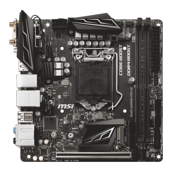
Page 21: Overview Of Components
Overview of Components Top View CPU_FAN1 CPU_PWR1 SYS_FAN1 CPU Socket DIMMA1 DIMMB1 JCI1 M2_3 ATX_PWR1 SYS_FAN2 JFP1 JFP2 JUSB1 JRGB1 SATA1 SATA2 SATA3 JUSB2 SATA4 JTPM1 M2_1 JAUD1 JBAT1 PCI_E1 Bottom View M2_2 Overview of Components... -
Page 22: Cpu Socket
Always unplug the power cord from the power outlet before installing or removing the CPU. Please retain the CPU protective cap after installing the processor. MSI will deal with Return Merchandise Authorization (RMA) requests if only the motherboard comes with the protective cap on the CPU socket. -
Page 23: Dimm Slots
DIMM Slots DIMMA1 DIMMB1 Channel A Channel B Memory module installation recommendation DIMMA1 DIMMB1 DIMMA1 Important Always insert memory modules in the DIMMA1 slot first. Due to chipset resource usage, the available capacity of memory will be a little less than the amount of installed. -
Page 24: Pci_E1: Pcie Expansion Slot
PCI_E1: PCIe 3.0 x16 (CPU lanes) Important If you install a large and heavy graphics card, you need to use a tool such as MSI Gaming Series Graphics Card Bolster to support its weight to prevent deformation of the slot. -
Page 25: M2_1~2: M.2 Slots (Key M)
M2_1~2: M.2 Slots (Key M) Important Intel ® RST supports M2_2 slot only. ® Intel Optane™ Memory Ready for M2_2 slot only. Bottom view: M2_2 Top view: M2_1 Video Demonstration Watch the video to learn how to Install M.2 SSD. http://youtu.be/JCTFABytrYA Installing M.2 SSD 1. -
Page 26: Jfp1, Jfp2: Front Panel Connectors
Please keeping the LED strip shorter than 2 meters to prevent dimming. Always turn off the power supply and unplug the power cord from the power outlet before installing or removing the RGB LED strip. Please use MSI s software to control the extended LED strip. Overview of Components... -
Page 27: Cpu_Pwr1, Atx_Pwr1: Power Connectors
CPU_PWR1, ATX_PWR1: Power Connectors These connectors allow you to connect an ATX power supply. CPU_PWR1 Ground +12V Ground +12V Ground +12V Ground +12V +3.3V +3.3V +3.3V -12V Ground Ground PS-ON# Ground Ground Ground ATX_PWR1 Ground Ground PWR OK 5VSB +12V +12V +3.3V Ground... -
Page 28: Jusb1: Usb 2.0 Connector
JUSB1: USB 2.0 Connector These connectors allow you to connect USB 2.0 ports on the front panel. USB0- USB1- USB0+ USB1+ Ground Ground No Pin Important Note that the VCC and Ground pins must be connected correctly to avoid possible damage. -
Page 29: Cpu_Fan1, Sys_Fan1~2: Fan Connectors
CPU_FAN1, SYS_FAN1~2: Fan Connectors Fan connectors can be classified as PWM (Pulse Width Modulation) Mode or DC Mode. PWM Mode fan connectors provide constant 12V output and adjust fan speed with speed control signal. DC Mode fan connectors control fan speed by changing voltage. When you plug a 3-pin (Non-PWM) fan to a fan connector in PWM mode, the fan speed will always maintain at 100%, which might create a lot of noise. -
Page 30: Jci1: Chassis Intrusion Connector
JCI1: Chassis Intrusion Connector This connector allows you to connect the chassis intrusion switch cable. Normal Trigger the chassis intrusion event (default) Using chassis intrusion detector 1. Connect the JCI1 connector to the chassis intrusion switch/ sensor on the chassis. 2. -
Page 31: Jbat1: Clear Cmos (Reset Bios) Jumper
JBAT1: Clear CMOS (Reset BIOS) Jumper There is CMOS memory onboard that is external powered from a battery located on the motherboard to save system configuration data. If you want to clear the system configuration, set the jumpers to clear the CMOS memory. Keep Data Clear CMOS/ Reset BIOS... -
Page 32: Bios Setup
Press Delete key, when the Press DEL key to enter Setup Menu, F11 to enter Boot Menu message appears on the screen during the boot process. Use MSI FAST BOOT application. Click on GO2BIOS button and choose OK. The system will reboot and enter BIOS setup directly. -
Page 33: Resetting Bios
Updating BIOS Updating BIOS with M-FLASH Before updating: Please download the latest BIOS file that matches your motherboard model from MSI website. And then save the BIOS file into the USB flash drive. Updating BIOS: 1. Insert the USB flash drive that contains the update file into the computer. -
Page 34: Ez Mode
EZ Mode At EZ mode, it provides the basic system information and allows you to configure the basic setting. To configure the advanced BIOS settings, please enter the Advanced Mode by pressing the Setup Mode switch or F7 function key. XMP switch Setup Mode switch Screenshot... - Page 35 Information display - click on the CPU, Memory, Storage, Fan Info and Help buttons on left side to display related information. Function buttons - enable or disable the LAN Option ROM, M.2/ Optane Genie, HD audio controller, AHCI, Optane, CPU Fan Fail Warning Control and BIOS Log Review by clicking on their respective button.
-
Page 36: Advanced Mode
Advanced Mode Press Setup Mode switch or F7 function key can switch between EZ Mode and Advanced Mode in BIOS setup. XMP switch Setup Mode switch Screenshot Search Language System information Boot device priority bar BIOS menu BIOS menu selection selection Menu display XMP switch/ Setup Mode switch/ Screenshot/ Language/ System information/ Boot... -
Page 37: Oc Menu
OC Menu This menu is for advanced users who want to overclock the motherboard. Important Overclocking your PC manually is only recommended for advanced users. Overclocking is not guaranteed, and if done improperly, it could void your warranty or severely damage your hardware. OC Explore Mode [Normal] Enables or disables to show the normal or expert version of OC settings. - Page 38 CPU Ratio Offset When Running AVX [Auto] Sets a offset value to lower the CPU core ratio. It could be helpful for heat dissipation when running AVX instruction set. If set to Auto, BIOS will configure this setting automatically. This item appears when the installed CPU supports this function. Ring Ratio [Auto] Sets the ring ratio.
- Page 39 Memory Try It ! [Disabled] It improve memory compatibility or performance by choosing optimized memory preset. DRAM Timing Mode [Link] Selects the memory timing mode. [Link] Allows user to configure the DRAM timing for all memory channel. [UnLink] Allows user to configure the DRAM timing for respective memory channel.
- Page 40 DIMMA1/B1 Memory SPD Press Enter to enter the sub-menu. The sub-menu displays the information of installed memory. Read only. CPU Features Press Enter to enter the sub-menu. Hyper-Threading [Enabled] Intel Hyper-Threading technology treats the multi cores inside the processor as multi logical processors that can execute instructions simultaneously.
- Page 41 Intel Adaptive Thermal Monitor [Enabled] Enables or disables the Intel adaptive thermal monitor function to protect the CPU from overheating. [Enabled] Throttles down the CPU core clock speed when the CPU is over the adaptive temperature. [Disabled] Disables this function. Intel C-State [Auto] Enables or disables the Intel C-state.
-
Page 42: Software Description
® Installing Drivers 1. Start up your computer in Windows ® ® 2. Insert MSI Driver Disc into your optical drive. 3. The installer will automatically appear and it will find and list all necessary drivers. 4. Click Install button. - Page 43 Inhalt Sicherheitshinweis ....................2 Spezifikationen ...................... 3 Rückseite E/A ......................7 LAN Port LED Zustandstabelle ................7 Konfiguration der Audioanschlüsse ............... 7 Realtek HD Audio Manager ..................8 Antennen installieren ................... 10 Übersicht der Komponenten ................11 CPU Sockel ......................12 DIMM-Steckplätze ....................
-
Page 44: Sicherheitshinweis
Sicherheitshinweis Die im Paket enthaltene Komponenten sind der Beschädigung durch elektrostatischen Entladung (ESD). Beachten Sie bitte die folgenden Hinweise, um die erfolgreichen Computermontage sicherzustellen. Stellen Sie sicher, dass alle Komponenten fest angeschlossen sind. Lockere Steckverbindungen können Probleme verursachen, zum Beispiel: Der Computer erkennt eine Komponente nicht oder startet nicht. -
Page 45: Spezifikationen
® ™ ** Bevor Sie Intel Optane Speichermodule verwenden, stellen Sie bitte über Downloads von der MSI Website sicher, dass die Treiber und das BIOS auf dem neuesten Stand sind. ® Intel B360 Chipsatz 2x USB 3.1 Gen2 (SuperSpeed USB 10Gbps) Typ-A Anschlüsse an der rückseitigen Anschlussleiste... - Page 46 Fortsetzung der vorherigen Seite ® Realtek ALC892 Codec Audio 7.1-Kanal-HD-Audio ® 1x Realtek RTL8111H-C Gigabit LAN Controller Intel ® Wireless-AC 9462 Karte Wireless LAN & Unterstützt Wi-Fi 802.11 a/b/g/n/ac, Dualband, MU-MIMO, ® Bluetooth mit Datenraten von bis zu 433 Mbps. Unterstützt Bluetooth ®...
- Page 47 SMART TOOL RAMDISK DPC LATENCY TUNER FAST BOOT Software X-BOOST GAMING APP SUPER CHARGER MYSTIC LIGHT Open Broadcaster Software (OBS) CPU-Z MSI GAMING ® Intel Extreme Tuning Utility ™ Google Chrome , Google Toolbar, Google Drive Norton ™ Internet Security Solution Fortsetzung auf der nächsten Seite...
- Page 48 Fortsetzung der vorherigen Seite Audio Audio Boost Netzwerk Intel WiFi Speicherung Twin Turbo M.2 Lüfter Smart-Lüftersteuerung Mystic Light Mystic Light Extension (RGB) Mystic Light SYNC EZ DEBUG LED Schutz Besondere Funktionen PCI-E Steel Armor Leistung DDR4 Boost Stabilität 7000+ Quality Test VR Ready Gamer-Erfahrungen GAMING HOTKEY...
-
Page 49: Rückseite E/A
Rückseite E/A Audioanschlüsse Wi-Fi Antennenanschlüsse PS/2 DVI-D USB 2.0 USB 3.1 Gen2 DisplayPort USB 3.1 Gen1 LAN Port LED Zustandstabelle Verbindung/ Aktivität LED Geschwindigkeit LED Zustand Bezeichnung Zustand Bezeichnung Keine Verbindung 10 Mbps-Verbindung Gelb Verbindung Grün 100 Mbps-Verbindung Blinkt Datenaktivität Orange 1 Gbps-Verbindung Konfiguration der Audioanschlüsse... -
Page 50: Realtek Hd Audio Manager
Realtek HD Audio Manager Nach der Installation des Realtek HD Audio-Treibers, wird das Symbol Realtek HD Audio Manager in der Taskleiste angezeigt. Klicken Sie doppelt auf dieses Symbol, um das Programm zu starten. Geräteauswahl Erweiterte Einstellungen Verbindungs- status Optimierungen Lautstärke Anschlüsse Profil Geräteauswahl - Ermöglicht die Auswahl der Audio-Ausgangs Quelle. - Page 51 Audiobuchsen für den Anschluss von einem Kopfhörer und Mikrofon Audiobuchsen für den Anschluss von einem Kopfhörer und Mikrofon AUDIO INPUT Audiobuchsen für 7.1 Kanal Anlage AUDIO INPUT Rear Front Side Center/ Subwoofer Rückseite E/A...
-
Page 52: Antennen Installieren
Antennen installieren 1. Schrauben Sie die Antennen fest an die Antennenanschlüsse, wie gezeigt. 2. Richten Sie die Antennenspitzen aus. Rückseite E/A... -
Page 53: Übersicht Der Komponenten
Übersicht der Komponenten Draufsicht CPU_FAN1 CPU_PWR1 SYS_FAN1 CPU Sockel DIMMA1 DIMMB1 JCI1 M2_3 ATX_PWR1 SYS_FAN2 JFP1 JFP2 JUSB1 JRGB1 SATA1 SATA2 SATA3 JUSB2 SATA4 JTPM1 M2_1 JAUD1 JBAT1 PCI_E1 Unteransicht M2_2 Übersicht der Komponenten... -
Page 54: Cpu Sockel
Sie jedoch bitte sicher, dass die betroffenen Komponenten mit den abweichenden Einstellungen während des Übertaktens zurecht kommen. Von jedem Versuch des Betriebes außerhalb der Produktspezifikationen kann nur abgeraten werden. MSI übernehmt keinerlei Garantie für die Schäden und Risiken, die aus einem unzulässigem Betrieb oder einem Betrieb außerhalb der Produktspezifikation resultieren. -
Page 55: Dimm-Steckplätze
DIMM-Steckplätze DIMMA1 DIMMB1 Kanal A Kanal B Speichermodul-Installationsempfehlung DIMMA1 DIMMB1 DIMMA1 Wichtig Um einen sicheren Systemstart zu gewährleisten, bestücken Sie immer DIMMA1 zuerst. Aufgrund der Chipsatzressourcennutzung wird die verfügbare Kapazität des Speichers kleiner sein als die Größe der installierten Speicherkapazität. Basierend auf der Intel CPU Spezifikation wird eine Speicherspannung unter 1,35 Volt vorgeschlagen, um die CPU zu schützen. -
Page 56: Pci_E1: Pcie Rweiterungssteckplatz
PCI_E1: PCIe Erweiterungssteckplatz PCI_E1: PCIe 3.0 x16 (CPU Lanes) Wichtig Wenn Sie eine große und schwere Grafikkarte einbauen, benötigen Sie einen Grafikkarten-Stabilisator (Graphics Card Bolster) der das Gewicht trägt und eine Verformung des Steckplatzes vermeidet. Achten Sie darauf, dass Sie den Strom abschalten und das Netzkabel aus der Steckdose herausziehen, bevor Sie eine Erweiterungskarte installieren oder entfernen. -
Page 57: M2_1~2: M.2 Steckplätze (Key M)
M2_1~2: M.2 Steckplätze (Key M) Wichtig Intel ® RST unterstützt nur M2_2-Steckplatz. ® ™ Intel Optane Technik unterstützt nur M2_2- Steckplatz. Unteransicht: M2_2 Draufsicht: M2_1 Video-Demonstration In diesem Video erfahren Sie, wie Sie die M.2 SSD installieren. http://youtu.be/JCTFABytrYA Installation einer M.2 SSD 1. -
Page 58: Jfp1, Jfp2: Frontpanel-Anschlüsse
Beachten Sie bitte, dass die Länge des LED-Streifens maximal 2 Meter betragen darf um eine Verdunkelung der LED zu verhindern. Schalten Sie die Stromversorgung aus und ziehen Sie das Netzkabel ab, bevor Sie die RGB-LED-Streifen ein- und ausbauen. Bitte verwenden Sie die MSI-Software zur Steuerung des LED-Leuchtstreifens. Übersicht der Komponenten... -
Page 59: Cpu_Pwr1, Atx_Pwr1: Stromanschlüsse
CPU_PWR1, ATX_PWR1: Stromanschlüsse Mit diesen Anschlüssen verbinden Sie die ATX Stromstecker. CPU_PWR1 Ground +12V Ground +12V Ground +12V Ground +12V +3.3V +3.3V +3.3V -12V Ground Ground PS-ON# Ground Ground Ground ATX_PWR1 Ground Ground PWR OK 5VSB +12V +12V +3.3V Ground Wichtig Stellen Sie sicher, dass alle Anschlüsse mit den richtigen Anschlüssen des Netzteils verbunden sind, um einen stabilen Betrieb der Hauptplatine sicherzustellen. -
Page 60: Jusb1: Usb 2.0 Anschluss
(Erdung) bezeichneten Pins korrekt verbinden müssen, ansonsten kann es zu Schäden kommen. Um ein iPad, iPhone und einen iPod über USB-Anschlüsse aufzuladen, installieren ® Sie bitte die MSI SUPER CHARGER Software. JUSB2: USB 3.1 Gen1 Anschluss Mit diesem Anschluss können Sie die USB 3.1 Gen1 Anschlüsse auf dem Frontpanel verbinden. -
Page 61: Cpu_Fan1, Sys_Fan1~2: Stromanschlüsse Für Lüfter
CPU_FAN1, SYS_FAN1~2: Stromanschlüsse für Lüfter Diese Anschlüsse können im PWM (Pulse Width Modulation) Modus oder Spannungsmodus betrieben werden. Im PWM-Modus bieten die Lüfteranschlüsse konstante 12 V Ausgang und regeln die Lüftergeschwindigkeit per Drehzahlsteuersignal. Im DC-Modus bestimmen die Lüfteranschlüsse die Lüftergeschwindigkeit durch Ändern der Spannung. Wenn Sie ein 3-Pin (Non-PWM) Lüfter an einen PWM-Modus Lüfteranschluss anschließen, läuft der Lüfter mit höchster Drehzahl und kann unangenehm laut werden. -
Page 62: Jci1: Gehäusekontaktanschluss
JCI1: Gehäusekontaktanschluss Dieser Anschluss wird mit einem Kontaktschalter verbunden. Normal Löse den Gehäuseeingriff aus (Standardwert) Gehäusekontakt-Detektor verwenden 1. Schließen Sie den JCI1-Anschluss am Gehäusekontakt-Schalter/ Sensor am Gehäuse an. 2. Schließen Sie die Gehäuseabdeckung. 3. Gehen Sie zu BIOS > Settings > Security > Chassis Intrusion Configuration. 4. -
Page 63: Jbat1: Clear Cmos Steckbrücke (Reset Bios)
JBAT1: Clear CMOS Steckbrücke (Reset BIOS) Der Onboard CMOS Speicher (RAM) wird durch eine externe Spannungsversorgung durch eine Batterie auf dem Motherboard versorgt, um die Daten der Systemkonfiguration zu speichern. Wenn Sie die Systemkonfiguration löschen wollen, müssen Sie die Steckbrücke für kurze Zeit umsetzen. Daten CMOS-Daten beibehalten... -
Page 64: Bios Setup
Während des BOOT-Vorgangs drücken Sie die Taste ENTF, wenn die Meldung Press DEL key to enter Setup Menu, F11 to enter Boot Menu erscheint. Verwenden Sie die MSI FAST BOOT Anwendung. Klicken Sie die GO2BIOS-Taste und drücken Sie OK. Das System startet neu und geht direkt ins BIOS. -
Page 65: Reset Des Bios
Aktualisierung des BIOS mit dem M-FLASH-Programm Vorbereitung: Laden Sie bitte die neueste BIOS Version, die dem Motherboard-Modell entspricht, von der offiziellen MSI Website herunter und speichern Sie die BIOS-Datei auf USB-Flash- Laufwerk. BIOS-Aktualisierungsschritte: 1. Schließen das USB-Flashlaufwerk mit der BIOS-Datei an den Computer. -
Page 66: Ez Modus
EZ Modus Im EZ-Modus können Sie die Grundinformationen des Systems einsehen und grundlegende Einstellungen konfigurieren. Um sich die erweiterten BIOS- Einstellungen anzeigen zu lassen, aktivieren Sie bitte den Erweiterten Modus durch Drücken des Setup Modus Schalter oder der Funktionstaste F7. XMP Schalter Setup Modus Schalter Screenshot... - Page 67 Informationsanzeige - Klicken Sie auf die Schaltfläche CPU, Memory, Storage, Fan Info und Help auf der linken Seite, um die jeweiligen Informationen anzuzeigen. Funktionstasten - Aktivieren oder deaktivieren Sie LAN Option ROM, M.2/ Optane Genie, HD audio controller, AHCI, Optane, CPU Fan Fail Warning Control und BIOS Log Review durch Anklicken der zugehörigen Schaltfläche.
-
Page 68: Erweiterter Modus
Erweiterter Modus Drücken Sie den Setup Modus Schalter oder die Funkionstaste F7, um zwischen dem EZ-Modus und Erweiterten-Modus im BIOS-Setup zu wechseln. XMP Schalter Setup Modus Schalter Screenshot Suchen Sprache System- information Bootgeräte- Prioritätsleiste BIOS-Menü BIOS-Menü -Auswahl -Auswahl Menüanzeige XMP Schalter/ Setup Modus Schalter/ Screenshot/ Sprache/ Systeminformation/ Boot-Geräte Prioritätsleiste - Finden Sie die Informationen in den Beschreibungen der EZ Modus-Abschritt. -
Page 69: Oc Menü
OC Menü In diesem Menü können Benutzer das BIOS anpassen und das Mainboard übertakten. Bitte führen Sie nur Änderungen durch, wenn Sie sich über das Ergebnis im Klaren sind. Sie sollten Erfahrung beim Übertakten haben, da Sie sonst das Motherboard oder Komponenten des Systems beschädigen können. - Page 70 Adjusted CPU Frequency Zeigt die eingestellte Frequenz der CPU an. Es handelt sich um eine Anzeige – Änderungen sind nicht möglich. Core X X of X xxxx MHz [Auto]* Hier können Sie die CPU Taktraten der verschiedenen aktiven Kerne anpassen. Diese Optionen kann nur geändert werden, wenn CPU Ratio Apply Mode auf Per Core eingestellt.
- Page 71 Extreme Memory Profile (X.M.P.) [Disabled] Extreme Memory Profile (XMP) basieren auf Zertifizierungen für Speichermodule aus dem PC-Bereich. Aktivieren Sie die Funktion XMP oder wählen Sie ein Profil des Speichermoduls zum Übertakten aus. Diese Option steht zur Verfügung, wenn die installierten Speichermodule die XMP Technik unterstützen. DRAM Reference Clock [Auto]* Setzen Sie den DRAM-Referenztakt.
- Page 72 CPU Memory Changed Detect [Enabled]* Aktiviert/ Deaktiviert die Systemwarnmeldung beim Booten, wenn die CPU oder der Hauptspeicher ersetzt wurde. [Enabled] Das System zeigt eine Warnmeldung beim Systemstart und lädt die Default-Einstellungen für neue Geräte. [Disabled] Deaktivierung der Funktion und Beibehaltung der aktuellen BIOS- Einstellungen.
- Page 73 Intel Virtualization Tech [Enabled] Aktiviert oder deaktiviert die Intel Virtualization Technologie. [Enabled] Aktiviert die Intel Virtualization-Technologie, die es mehreren Betriebssystemen ermöglicht, in voneinander unabhängigen Partitionen zu arbeiten. Das System kann als mehrere Systeme virtuell einsetzen. [Disabled] Deaktiviert diese Funktion. Intel VT-D Tech [Disabled] Aktiviert oder deaktiviert die Intel VT-D (Intel Virtualization for Directed I/O) Technologie.
- Page 74 Package C State limit [Auto] Hier können Sie einen CPU C-State-Modus für Stromsparen auswählen, wenn das System im Leerlauf ist. Die Optionen des C-States ist abhängig von der installierten CPU. Diese Option wird angezeigt, wenn Intel C-State aktiviert ist. CFG Lock [Enabled] Hier können Sie einen CPU C-State-Modus für Stromsparen auswählen, wenn das System im Leerlauf ist.
-
Page 75: Softwarebeschreibung
Installation von Treibern 1. Starten Sie Ihren Computer mit Windows ® ® 2. Legen Sie die MSI Treiber Disk in das optisches Laufwerk. 3. Der Installer wird automatisch erscheint und findet und finden Sie die benötigten Treiber in die Liste. - Page 76 NOTE NOTE...
- Page 77 Table des matières Informations de sécurité ..................2 Spécifications ......................3 Panneau arrière Entrée/ Sortie ................7 Tableau explicatif de l état de la LED du port LAN ..........7 Configuration des ports audio ................7 Realtek HD Audio Manager ..................8 Installation des antennes ..................
-
Page 78: Informations De Sécurité
Informations de sécurité Les composants dans l emballage peuvent être endommagés par des décharges électrostatiques (ESD). Pour vous assurer de correctement monter votre ordinateur, veuillez vous référer aux instructions ci-dessous. Assurez-vous de bien connecter tous les composants. En cas de mauvaise connexion, il se peut que l ordinateur ne reconnaisse pas le composant et que le démarrage échoue. -
Page 79: Spécifications
Support non-ECC, mémoire un-buffered ® Support Intel Extreme Memory Profile (XMP) * Veuillez vous référer au site www.msi.com pour plus d informations sur la mémoire compatible. Slots d extension 1 x slot PCIe 3.0 x16 1 x port DVI-D, supportant une résolution maximum de 1920x1200@60Hz Sorties vidéo... - Page 80 Suite du tableau de la page précédente ® Realtek ALC892 Codec Audio Audio haute définition 7.1 ® 1 x contrôleur Realtek RTL8111H-C Gigabit LAN Carte Intel ® Wireless-AC 9462 Wireless LAN et Support Wi-Fi 802.11 a/b/g/n/ac, Double Bande, MU- Bluetooth ®...
- Page 81 FAST BOOT Logiciel X-BOOST GAMING APP SUPER CHARGER MYSTIC LIGHT Open Broadcaster Software (OBS) CPU-Z MSI GAMING ® Intel Extreme Tuning Utility Google Chrome™, Google Toolbar et Google Drive Norton™ Internet Security Solution Suite du tableau sur la page suivante...
- Page 82 Suite du tableau de la page précédente Audio Audio Boost Network Intel WiFi Stockage Twin Turbo M.2 Ventilateur Contrôle des ventilateurs Mystic Light Mystic Light Extension(RGB) Mystic light SYNC EZ DEBUG LED Protection Fonctions spéciales Steel Armor PCI-E Performance DDR4 Boost Stabilité...
-
Page 83: Panneau Arrière Entrée/ Sortie
Panneau arrière Entrée/ Sortie Ports audio Connecteurs PS/2 d antenne Wi-Fi DVI-D USB 2.0 USB 3.1 Gen2 DisplayPort USB 3.1 Gen1 Tableau explicatif de l état de la LED du port LAN LED indiquant la connexion LED indiquant la vitesse et l activité... -
Page 84: Realtek Hd Audio Manager
Realtek HD Audio Manager Après l installation du pilote Realtek HD Audio, l icône Realtek HD Audio Manager apparaît dans la barre des tâches du système. Double-cliquez sur l icône pour lancer le programme. Sélection du périphérique Paramètres avancés Etat des prises Jack Amélioration d application... - Page 85 Ilustration de l utilisation des ports audio dédiés au casque et au microphone Ilustration de l utilisation du port audio dédié aux haut-parleurs AUDIO INPUT Ilustration de l utilisation des ports audio dédiés aux haut-parleurs 7.1 AUDIO INPUT Rear Front Side Center/ Subwoofer...
-
Page 86: Installation Des Antennes
Installation des antennes 1. Vissez fermement les antennes aux connecteurs dédiés, comme illustré ici. 2. Orientez les antennes. Panneau arrière Entrée/ Sortie... -
Page 87: Vue D Ensemble Des Composants
Vue d ensemble des composants Vue de dessus CPU_FAN1 CPU_PWR1 SYS_FAN1 Socket processeur DIMMA1 DIMMB1 JCI1 M2_3 ATX_PWR1 SYS_FAN2 JFP1 JFP2 JUSB1 JRGB1 SATA1 SATA2 SATA3 JUSB2 SATA4 JTPM1 M2_1 JAUD1 JBAT1 PCI_E1 Vue de dessous M2_2 Vue d ensemble des composants... -
Page 88: Socket Processeur
électrique. Veuillez garder le capot de protection du processeur après l installation du processeur. Selon les exigences de RMA (Return Merchandise Authorization), MSI n acceptera pas les cartes mère dont le capot de protection aura été retiré. -
Page 89: Slots Dimm
Slots DIMM DIMMA1 DIMMB1 Canal A Canal B Installation recommandée de module mémoire DIMMA1 DIMMB1 DIMMA1 Important Veillez à toujours insérer un module de mémoire dans l emplacement DIMMA1 en premier. Du fait des ressources utilisées par le chipset, la capacité de mémoire disponible est un peu moins élevée que celle installée. -
Page 90: Pci_E1 : Slot D Extension Pcie
Important Si vous installez une carte graphique lourde, il vous faut utiliser un outil comme la barre de support MSI Gaming Series pour supporter son poids et pour éviter la déformation du slot. Veillez à toujours mettre l ordinateur hors tension et à débrancher le cordon d alimentation avant d installer les cartes d extension. -
Page 91: M2_1~2 : Slots M.2 (Touche M)
M2_1~2 : Slots M.2 (Touche M) Important La technologie Intel ® RST ne supporte que le slot M2_2. ® Intel Optane™ Memory Ready uniquement pour le slot M2_2. Vue de dessous : M2_2 Vue de dessus : M2_1 Vidéo de démonstration Référez-vous à... -
Page 92: Jfp1, Jfp2 : Connecteurs De Panneau Avant
Avant d installer ou de retirer le ruban LED RGB, veillez à toujours éteindre l alimentation et à débrancher le câble d alimentation de la prise électrique. Veuillez utiliser un logiciel MSI dédié pour contrôler le ruban d extension LED. Vue d ensemble des composants... -
Page 93: Cpu_Pwr1, Atx_Pwr1 : Connecteurs D Alimentation
CPU_PWR1, ATX_PWR1 : Connecteurs d alimentation Ces connecteurs vous permettent de relier une alimentation ATX. CPU_PWR1 Ground +12V Ground +12V Ground +12V Ground +12V +3.3V +3.3V +3.3V -12V Ground Ground PS-ON# Ground Ground Ground ATX_PWR1 Ground Ground PWR OK 5VSB +12V +12V +3.3V... -
Page 94: Jusb1 : Connecteur Usb 2.0
éviter tout dommage sur la carte mère. Pour recharger votre iPad, iPhone et iPod par l intermédiaire d un port USB, ® veuillez installer l utilitaire MSI SUPER CHARGER. JUSB2 : Connecteur USB 3.1 Gen1 Ce connecteur vous permet de relier un port USB 3.1 Gen1 sur le panneau avant. -
Page 95: Cpu_Fan1, Sys_Fan1~2 : Connecteurs Pour Ventilateurs
CPU_FAN1, SYS_FAN1~2 : Connecteurs pour ventilateurs Les connecteurs pour ventilateurs peuvent être utilisés en mode PWM (Pulse Width Modulation) et en mode DC. En mode PWM, les connecteurs fournissent une sortie de 12V constante et ajustent la vitesse des ventilateurs avec un signal de contrôle de vitesse. -
Page 96: Jci1 : Connecteur Intrusion Châssis
JCI1 : Connecteur intrusion châssis Ce connecteur est relié à un câble d interrupteur intrusion châssis. Normal Commencer l activité intrusion châssis (défaut) Utilisation du détecteur d intrusion châssis 1. Reliez le connecteur JCI1 à l interrupteur ou au capteur d intrusion châssis situé sur le boîtier du PC. -
Page 97: Jbat1 : Cavalier Clear Cmos (Réinitialisation Bios)
JBAT1 : Cavalier Clear CMOS (Réinitialisation BIOS) Une mémoire CMOS est intégrée et est alimentée en externe par une batterie située sur la carte mère afin de conserver les données de configuration système. Si vous souhaitez nettoyer la configuration système, placez le cavalier sur Effacer CMOS de manière à... -
Page 98: Configuration Du Bios
Menu, F11 to enter Boot Menu sur l écran, veuillez appuyer sur la touche Suppr. Quand l ordinateur est déjà en marche, vous pouvez utiliser l application MSI FAST BOOT. Cliquez sur le bouton GO2BIOS puis sur OK. Le système redémarre et entre dans l interface Setup du BIOS. -
Page 99: Réinitialiser Le Bios
Avant la mise à jour : Veuillez télécharger la dernière version de BIOS compatible à votre carte mère sur le site MSI. Ensuite, veuillez sauvegarder le nouveau BIOS sur le lecteur flash USB. Mettre le BIOS à jour : 1. Connectez le lecteur Flash USB contenant le profil à l ordinateur. -
Page 100: Ez Mode (Mode Simplifié)
EZ Mode (mode simplifié) Le mode EZ vous fournit les informations basiques du système et vous permet de configurer les réglages de base. Si vous souhaitez configurer les réglages du BIOS, veuillez utiliser le mode Advanced en appuyant sur le switch Setup Mode (Interrupteur de modes de réglages) ou la touche de fonction F7. - Page 101 Ecran d informations - cliquez sur les boutons CPU (Processeur), Memory (Mémoire), Storage (Stockage), Fan Info (Info ventilateurs) et Help (Aide) à gauche de la fenêtre pour obtenir les informations respectives. Boutons de fonction - en cliquant sur leur bouton respectif, vous pourrez activer les fonctions LAN Option ROM, M.2/ Optane Genie, HD audio controller, AHCI, Optane, CPU Fan Fail Warning Control et BIOS Log Review.
-
Page 102: Advanced Mode (Mode Avancé)
Advanced Mode (mode avancé) Appuyez sur le Setup Mode switch (interrupteur de modes de réglages) ou sur la touche de fonction F7 pour commuter entre le mode simplifié et le mode avancé. Interrupteur de Capture Interrupteur XMP Recherche modes de réglages d écran Langue Information... -
Page 103: Oc Menu (Menu Overclocking)
OC Menu (menu overclocking) Ce menu est destiné aux utilisateurs avancés souhaitant overclocker leur carte mère. Important L overclocking manuel du PC n est recommandé que pour les utilisateurs avancés. L overclocking n est pas garanti et une mauvaise manipulation peut rendre nulle votre garantie et sévèrement endommager votre matériel. - Page 104 CPU Ratio Offset When Running AVX [Auto] Définit une valeur de décalage pour réduire le ratio du coeur CPU. Cela est utile pour la dissipation de chaleur lors de l exécution du jeu d instruction AVX. Mis en Auto, le BIOS configure ce réglages automatiquement. Ce menu apparaît lorsque le processeur installé...
- Page 105 DRAM Frequency [Auto] Définit la fréquence de la mémoire. Veuillez noter que les résultats de l overclocking ne sont pas garantis. Adjusted DRAM Frequency Affiche la fréquence ajustée de la mémoire. Fonctionne en lecture seule. Memory Try It ! [Disabled] Memory Try It! permet d améliorer la compatibilité...
- Page 106 CPU Technology Support Appuyez sur la touche Entrée pour accéder au sous-menu. Ce sous-menu affiche les principales fonctions et technologies prises en charge par le processeur installé. Fonctionne en lecture seule. MEMORY-Z Appuyez sur la touche Entrée pour accéder au sous-menu. Ce sous-menu affiche tous les réglages et timings de la mémoire installée.
- Page 107 Adjacent Cache Line Prefetch [Enabled] Active ou désactive le prefetcher matériel du processeur (MLC Spatial prefetcher). [Enabled] Active le prefetcher de la ligne de cache adjacente pour réduire le temps de latence et ajuster les performances dans l application spécifique. [Disabled] Active seulement la ligne de cache exigée.
- Page 108 Short Duration Power Limit (W) [Auto] Définit le niveau d alimentation maximum que le TDP (enveloppe thermique) du processeur peut supporter sur une courte période et en mode Turbo Boost. CPU Current Limit (A) [Auto] Définit le niveau d alimentation maximum du package du processeur en mode Turbo Boost.
-
Page 109: Informations Sur Les Logiciels
Installer les pilotes 1. Allumez l ordinateur sous Windows ® ® 2. Insérez le disque MSI Driver Disc dans le lecteur optique. 3. L outil d installation apparaît automatiquement. Il trouvera et listera tous les pilotes dont vous avez besoin. - Page 110 NOTE NOTE...
- Page 111 ............2 ................ 3 ............7 LAN ........... 7 ................7 Realtek HD Audio ................8 ....................10 ............... 11 ..................12 DIMM ......................13 PCI_E1: PCIe ............... 14 SATA1~4: SATA 6 / ................14 M2_1~2: M.2 ( M) ................ 15 JFP1, JFP2: ............
- Page 112 60 C (140 F),...
- Page 113 Pentium Gold Celeron LGA1151 ® Intel B360 DDR4 DDR4 2666/ 2400/ 2133 non-ECC, ® Intel Extreme Memory Profile (XMP) www.msi.com PCIe 3.0 x16 DVI-D, 1920x1200@60 DisplayPort 1.2, 4096x2304@60 ® Intel B360 SATA 6 M.2 ( PCIe 3.0 x4 SATA 6...
- Page 114 ® Realtek ALC892 Codec 7.1- High Definition Audio ® Realtek RTL8111H-C ® Intel Wireless-AC 9462 ® Wi-Fi Bluetooth Wi-Fi 802.11 a/b/g/n/ac, MU-MIMO, ® Bluetooth Wi-Fi DVI-D DisplayPort PS/2 USB 2.0 Type-A LAN (RJ45) USB 3.1 Gen2 Type-A USB 3.1 Gen1 Type-A 1x 24- 1x 8- ATX 12...
- Page 115 LIVE UPDATE 6 SMART TOOL RAMDISK DPC LATENCY TUNER FAST BOOT X-BOOST GAMING APP SUPER CHARGER MYSTIC LIGHT Open Broadcaster Software (OBS) CPU-Z MSI GAMING Intel ® Extreme Tuning Utility Google Chrome™, Google Toolbar, Google Drive Norton™ Internet Security Solution...
- Page 116 Audio Boost Intel WiFi Twin Turbo M.2 Mystic Light Mystic Light Extension(RGB) Mystic light SYNC EZ DEBUG LED PCI-E Steel Armor DDR4 Boost 7000+ Quality Test VR Ready GAMING HOTKEY GAMING MOUSE Control BIOS Click BIOS 5 GAMING Certified...
-
Page 117: Lan
PS/2 Wi-Fi DVI-D USB 2.0 USB 3.1 Gen2 DisplayPort USB 3.1 Gen1... -
Page 118: Realtek Hd Audio
Realtek HD Audio Realtek HD Audio, Realtek HD Audio Manager. - Page 119 AUDIO INPUT AUDIO INPUT Rear Front Side Center/ Subwoofer...
- Page 121 CPU_FAN1 CPU_PWR1 SYS_FAN1 DIMMA1 DIMMB1 JCI1 M2_3 ATX_PWR1 SYS_FAN2 JFP1 JFP2 JUSB1 JRGB1 SATA1 SATA2 SATA3 JUSB2 SATA4 JTPM1 M2_1 JAUD1 JBAT1 PCI_E1 M2_2...
- Page 122 DIMM. 50.13 LGA 1151 LGA 1151 « » ITX, Intel LGA 1151 ® , MSI « ». MSI®...
-
Page 123: Dimm
DIMM DIMMA1 DIMMB1 DIMMA1 DIMMB1 DIMMA1 DIMMA1. DIMM 1.35 . Windows, Windows. SPD (Serial Presence Detect). BIOS Memory Try It!,... -
Page 124: Sata 6
PCI_E1: PCIe PCI_E1: PCIe 3.0 x16 CPU) MSI Gaming Series Graphics Card Bolster SATA1~4: SATA 6 SATA 6 SATA. SATA1 SATA3 SATA2 SATA4 SATA SATA... - Page 125 M2_1~2: M.2 ( Intel ® M2_2 . ® Intel Optane™ M2_2. : M2_2 : M2_1 M.2 SSD. http://youtu.be/JCTFABytrYA M.2 SSD M.2 SSD. M.2 SSD M.2.
-
Page 126: Rgb Led
JFP1, JFP2: JFP1 HDD LED + Power LED + HDD LED - Power LED - Reset Switch Power Switch Reset Switch Power Switch Reserved No Pin Speaker - Buzzer + JFP2 Buzzer - Speaker + JRGB1: RGB LED 5050 RGB 12 . -
Page 127: Cpu_Pwr1, Atx_Pwr1
CPU_PWR1, ATX_PWR1: ATX. CPU_PWR1 Ground +12V Ground +12V Ground +12V Ground +12V +3.3V +3.3V +3.3V -12V Ground Ground PS-ON# Ground Ground Ground ATX_PWR1 Ground Ground PWR OK 5VSB +12V +12V +3.3V Ground JAUD1: MIC L Ground MIC R Head Phone R MIC Detection SENSE_SEND No Pin... -
Page 128: Usb2.0
JUSB1: USB 2.0 USB 2.0 USB0- USB1- USB0+ USB1+ Ground Ground No Pin iPad, iPhone iPod USB, ® SUPER CHARGER. JUSB2: USB 3.1 Gen1 USB 3.1 Gen1 Power USB2.0+ USB3_RX_DN USB2.0- USB3_RX_DP Ground Ground USB3_TX_C_DP USB3_TX_C_DN USB3_TX_C_DN USB3_TX_C_DP Ground Ground USB3_RX_DP USB2.0- USB3_RX_DN... -
Page 129: Cpu_Fan1, Sys_Fan1~2
CPU_FAN1, SYS_FAN1~2: : PWM (PulseWidth Modulation) 12 , (Non-PWM) PWM, (PWM DC), CPU_FAN1 SYS_FAN1 SYS_FAN2 BIOS > HARDWARE MONITOR : PWM PWM/ DC. Ground +12V Ground Voltage Control Sense Speed Control Signal Sense... -
Page 130: Tpm
JCI1: JCI1. BIOS > Settings > Security > Chassis Intrusion Configuration. Chassis Intrusion Enabled. F10, Enter, Yes. BIOS > Settings > Security > Chassis Intrusion Configuration. Chassis Intrusion, Reset. F10, Enter, Yes. JTPM1: (Trusted Platform Module). LPC Clock 3V Standby power LPC Reset 3.3V Power LPC address &... -
Page 131: Bios
JBAT1: CMOS ( BIOS) CMOS CMOS BIOS BIOS JBAT1 5-10 JBAT1. CPU - DRAM - DRAM VGA - BOOT -... -
Page 132: Bios
BIOS BIOS, BIOS BIOS BIOS, HELP. BIOS BIOS. Delete, Press DEL key to enter Setup Menu, F11 to enter Boot Menu MSI FAST BOOT. GO2BIOS BIOS. GO2BIOS Memory-Z F10: F12: FAT / FAT32 Ctrl+F: BIOS... -
Page 133: Bios
Clear CMOS CMOS. BIOS, CMOS . BIOS BIOS M-FLASH BIOS MSI, BIOS USB. BIOS: USB, <Ctrl+F5> POST. BIOS BIOS. BIOS Live Update 6 BIOS: MSI LIVE UPDATE 6. BIOS Update. Scan. Download, BIOS. Next In Windows mode. Next Start BIOS. BIOS... - Page 134 BIOS, M-Flash XMP - X.M.P. (Extreme Memory Profile). X.M.P. X.M.P. F12, USB ( FAT/ FAT32). Ctrl + F BIOS. BIOS, F6, F10 F12. BIOS. BIOS BIOS...
- Page 135 CPU, Memory, Storage, Fan Info Help LAN Option ROM, M.2/ Optane Genie, HD audio controller, AHCI, Optane, CPU Fan Fail Warning Control BIOS Log Review, M-Flash - M-Flash. BIOS BIOS, BIOS. BIOS , OC..., . .) BIOS. 1~5 - BIOS BIOS 1~5) BIOS...
- Page 136 BIOS. BIOS BIOS XMP/ BIOS - SETTINGS - OC - M-FLASH - BIOS USB OC PROFILE - HARDWARE MONITOR - BOARD EXPLORER - BIOS BIOS...
- Page 137 « » OC Explore Mode [Normal] [Normal] BIOS. [Expert] BIOS Expert. CPU Ratio Apply Mode [All Core]* CPU. Turbo Boost. [All Core] CPU Ratio. CPU, CPU Ratio. [Per Core] Core X X of X xxxx MHz. [Turbo Ratio] X-Core Ratio Limit. X-Core Ratio Limit [Auto]* turbo boost.
- Page 138 Core X X of X xxxx MHz [Auto]* CPU Ratio Apply Mode Per Core. CPU Ratio Offset When Running AVX [Auto] AVX. Auto, BIOS Ring Ratio [Auto] Adjusted Ring Frequency Ring. GT Ratio [Auto] Adjusted GT Frequency Misc Setting* Enter, + EIST [Enabled]* ®...
- Page 139 DRAM Reference Clock [Auto]* DRAM. DRAM Frequency [Auto] DRAM. Adjusted DRAM Frequency DRAM. Memory Try It ! [Disabled] DRAM Timing Mode [Link] [Link] DRAM [UnLink] DRAM Advanced DRAM Configuration Enter CMOS CMOS/ CMOS BIOS, Memory Fast Boot [Auto]* [Auto] BIOS. [Enabled] [Disabled] DRAM Voltages control [Auto]...
- Page 140 CPU Memory Changed Detect [Enabled]* [Enabled] [Disabled] BIOS. CPU Specifications Enter CPU Technology Support Enter MEMORY-Z Enter DIMMA1/B1 Memory SPD Enter CPU Features Enter Hyper-Threading [Enabled] Intel Hyper-Threading [Enable] Intel Hyper-Threading. [Disabled] Active Processor Cores Control [All] Limit CPUID Maximum [Disabled] CPUID.
- Page 141 Intel Virtualization Tech [Enabled] Intel Virtualization. [Enabled] Intel Virtualization [Disabled] Intel VT-D Tech [Disabled] Intel VT-D (Intel Virtualization for Direct I/O). Hardware Prefetcher [Enabled] (MLC Streamer prefetcher). [Enabled] [Disabled] Adjacent Cache Line Prefetch [Enabled] (MLC Spatial prefetcher). [Enabled] [Disabled] CPU AES Instructions [Enabled] CPU AES (Advanced Encryption Standard-New Instructions).
- Page 142 C1E Support [Disabled] Intel C-State. [Enabled] [Disabled] Package C State limit [Auto] C-state C-state Intel C-State. CFG Lock [Enabled] MSR 0xE2[15], CFG. [Enabled] CFG. [Disabled] CFG. Long Duration Power Limit (W) [Auto] Turbo Boost. Long Duration Maintained (s) [Auto] Long Duration Power Limit. Short Duration Power Limit (W) [Auto] Turbo Boost.
-
Page 143: Windows 10
® Windows Windows ® Restart POST (Power-On Self Test) Press any key to boot from CD or DVD... Windows ® Windows ® ® Driver Disc Install. ® Driver Disc Utilities. Install. - Page 145 Users should contact the local applicable European Harmonized Standards. authorized point of collection for The point of contact for regulatory matters is MSI, recycling and disposing of their end-of-life products. MSI-NL Eindhoven 5706 5692 ER Son. Visit the MSI website and locate a nearby distributor for further recycling information.
- Page 146 MSI will comply with the product take entregar a una empresa autorizada para la recogida de back requirements at the end of life of MSI-branded estos residuos.
- Page 147 K t ngày 01/12/2012, t t c các s n ph m do công illetve környezetvédőként fellépve az MSI emlékezteti ty MSI s n xu t tuân th Thông t s 30/2011/TT-BCT Önt, hogy ... quy đ nh t m th i v gi i h n hàm l ng cho phép c a...
- Page 148 Micro-Star Int l Co., Ltd. All other marks and names mentioned may be trademarks of their respective owners. No warranty as to accuracy or completeness is expressed or implied. MSI reserves the right to make changes to this document without prior notice. Technical Support...
Need help?
Do you have a question about the B360I GAMING PRO AC and is the answer not in the manual?
Questions and answers