
Related Manuals for SANYU SY5000 Series


Summary of Contents for SANYU SY5000 Series
- Page 1 ﺑرق اﺗوﻣﺎﺳﯾون ﺻﻧﻌﺗﯽ و راﺑو اﻟﮑﺗرﯾﮏ SY5000 Series High-performance Vector Inverter Operating Instruction Manual Sanyu, controlling and protecting your motor Shanghai Sanyu Industry Co., Ltd 0912 433 43 19 33 11 61 33, 32...
-
Page 2: Table Of Contents
Contents 1 Safety Precautions and Product Model ................1 1.1 Safety Precautions ....................1 1.2 Nameplate Introduction: ..................2 VFD Series Type ..................... 3 1.4 Technical Index and Specification ................3 2 Installation and wiring......................8 2.1 Operation Environment ..................9 2.2 Installing Direction and Space ................ - Page 3 3.2 LED and Indicator Light Description: ..............20 3.3 Monitoring Parameter Display ................. 22 3.4 Run Status Parameter Display .................. 22 3.5 Malfunction Alarm Display ..................23 3.6 Function Code Editing Display .................. 24 3.7 Monitoring Parameter ..................... 25 3.8 Function Code Setting ....................26 3.9 User Password Setting and Function Code Edit ............
- Page 4 5.9 Communication Address of all Parameters: ............248 6 Troubleshooting ........................ 249 6.1 Fault information and Troubleshooting ..............249 6.2 Abnormal Phenomena Solution ................254 7 Maintenance ........................257 7.1 Routine Maintenance ..................257 Periodic Maintenance ..................257...
-
Page 5: Safety Precautions And Product Model
1 Safety Precautions and Product Model 1.1 Safety Precautions ▲ Do not install this equipment in an explosive gas atmosphere, or there will be explosion hazards. ▲ Only qualified individuals should proceed with wiring, or there will be electric shock hazards. Do not conduct any wiring during the system power on to avoid the electric shock.. -
Page 6: Nameplate Introduction
1.2 Nameplate Introduction: 1.2.1Denomination rules 1.2.2 Nameplate SANYU MODEL: SY5000-2R2G-4 POWER: 2.2 KW INPUT: 3PH AC380V 50HZ OUTPUT: 5.0A 0~300HZ... -
Page 7: Vfd Series Type
1.3 VFD Series Type Rated Output Adapted Motor Voltage Classes Rated Power(KW) (KW) Current(A) 0.75 0.75 220V 1-phase 0.75 0.75 380V 3-phase 1.4 Technical Index and Specification Rated Voltage, 3-phase(4#sereis)380V;50/60HZ Frequency 1-phase(S2#series)220V;50/60HZ Allowed 3-phase(4#series)320V~460V Voltage Range 1-phase(S2#series)160V~260V... - Page 8 4#series; 0~460V Voltage S2#series; 0~260V frequency Low frequency mode: 0~300HZ ; High frequency mode: 0~3000HZ Overload G type: 110% for long-term, 150% for 1 min, 180% for 5s Capacity P type: 105% for long-term, 120% for 1 min, 150% for 1s Control Mode V/F control, advanced V/F control, V/F separation control, electric current vector control Frequency...
- Page 9 Operating speed precision in steady state: ≤±0.5% rated synchronous speed Torque response: ≤50ms VC, SVC, FVC ≤20ms Being able to detect parameter automatically under static Motor Parameter state and dynamic state of motor, thus guarantee an optimum Self-measurement control. Current Voltage Current closed-loop control, free from current impact, perfect Restrain...
- Page 10 Automatic Dynamic steady state, static steady state, and unsteady voltage for choices to obtain the Steady-voltage steadiest operation Operation Acceleration 0.1s~3600min continuous setting, S type and linear type mode for choice Deceleration Time Setting Dynamic braking initial voltage, backlash voltage and dynamic braking continuous adjustable Halt DC braking initial frequency: 0.00~[F0.16] upper limit frequency Braking time: 0.0~100.0s;...
- Page 11 Upper limit and lower limit frequency setting, frequency hopping operation, reversal Operation running restraint, slip frequency compensation, RS485 communication, frequency control of Function progressive increase and decrease, failure recovery automatically, etc. Output frequency, output current, output voltage, motor speed, set frequency, module temperature, PID setting, feedback, analog input and output.
-
Page 12: Installation And Wiring
2 Installation and wiring DANGER nsure the power has been cut off before wiring. Electric chock and fire hazard. 2. Ask electric engineering professionals to conduct wiring. Electric chock and fire hazard. 3. Earth terminals must be reliable grounded. (380V class: especially the third grounding) Electric shock and fire hazard. -
Page 13: Operation Environment
CAUTION 1. Check if the voltage of power inlet wire agrees with rated input voltage of VFD. Injury and fire hazard. 2. Connect brake resistor or brake unit according to wiring diagram. Fire hazard. 3. Choose screw driver and wrench with specified torque to fasten terminals. Fire hazard. -
Page 14: Installing Direction And Space
and heat dissipation. The service life of VFD lies in installing environment and operation condition. But even in standard environment, a long-term continuous running can guarantee a life of no more than 5 years for electrolytic capacitor and about 3 years for cooling fan. An update or a thorough maintenance in advance is recommended. 2.2 Installing Direction and Space To ensure a good cooling cycle, the VFD must be installed vertically, and keep enough space from surroundings. - Page 15 Model Motor B(mm H1(mm) H(mm) W(mm) D(mm) d(mm Weight(Kg) (mm power ) SY5000-0R7G-4 0.75 174.5 184.5 1.95 SY5000-1R5G-4 SY5000-2R2G-4 SY5000-004G-4 148.5 SY5000-5R5G-4 SY5000-7R5G SY5000-011G-4 SY5000-015G-4...
-
Page 16: Basic Running Wiring
2.5 Basic Running Wiring The wiring parts of VFD include major loop and control loop. Open the cover of I/O terminals, users can see the major loop terminal and control loop terminal, and must conduct the wiring according to the following diagram. -
Page 17: Major Loop Terminal Wiring
2.6 Major Loop Terminal Wiring 2.7 Major Loop Terminal Diagram 2.8 Control Loop Terminal Diagram... -
Page 18: Control Loop Terminal Function Table
2.9 Control Loop Terminal Function Table Functional Specification of Control Loop Terminal Terminal Category Functions Specification Number Effective when short circuit between(X1、X2、X3、 X4、 X5、 X6、 X7) ~COM, and the functions are set Multi-functiona by parameters F7.00~F7.06(common port: COM) INPUT, 0~24V level signal, low l Digital Input level effective, 5mA. - Page 19 Can be programmed as impulse output terminal OUTPUT, output frequency of various functions as many as 13 kinds (common rangeF6.32~F6.35, set maximum port: COM). See F6.23. frequency as high as 50KHz. AI1 receives voltage/current input. Jumper JP3 (for jumper terminal AI1) can select voltage or current input mode, and voltage input is the INPUT, input voltage range: 0~...
-
Page 20: Dial Switch
conduct corresponding jumper on master control board according to signal type. ▲ Connecting week analog signal is easily affected by external disturbance. So wiring should be as short as possible. The external control line should be set with isolating device or shielding line, and should be grounded. ▲... -
Page 21: Wiring Notices
Vout2 AO2 output voltage signal Cout2 AO2 output current signal AO2 of AO2/DO is effective, output voltage signal DO of AO2/DO is effective, output pulse signal Non-connecting for matched resistance of 485 communication Connecting for matched resistance of 485 communication AI1 input current signal AI1 input voltage signal Vout1... -
Page 22: Spare Circuit
exceeds 4kHz, make an appropriate reduction of the distance, and better lay the wire in metal tube. When adding peripherals (filters, reactors, etc.) to the VFD, check the ground resistance with 1000V tramegger and ensure the value is above 4 MΩ. Do not add phase advance capacitor or RC snubber to the U, V, W terminal of VFD. -
Page 23: Operation Panel And Operation Method
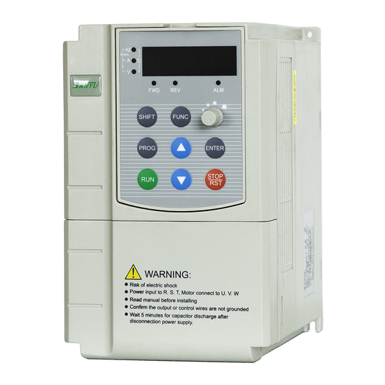
3 Operation Panel and Operation Method 3.1 Operation Panel Keys Name Function Description programmin Enter or escape from programming g/escape key Choose the bit of the data which is to be set and modified when the VFD is shift/monito in edit status; switch monitor parameter to be shown when the VFD is in r key other modes. -
Page 24: Led And Indicator Light Description
Enter key Enter into sub-menu items or confirm data. According to the setting of function parameter FE.01, jog or reverse run, and Function key frequency clearance is available when pressing this key under keypad mode. Run key Enter into run mode under keypad model. In common run status the VFD will be stopped according to set mode after stop/reset press this key if run command channel is set as keyboard stop effective... - Page 25 Hz, A, V Displayed physical quantity unit (current A, voltage V, frequency Hz) Alarm indicator light, indicate that the VFD is in over current or over voltage suppressing status or failure alarm status currently. This indicator light turns green when the VFD is in forward running status. This indicator light turns red when the VFD is in reverse running status.
-
Page 26: Monitoring Parameter Display
3.3 Monitoring Parameter Display Keypad display status is classified as power-on initialization display, function code and monitoring parameters display, malfunction alarm status display, run status parameters display. After power-on, LED will display “P.OFF”, then enter setting frequency display status. When the VFD is stopped, the keypad displays stopped state monitoring parameters, factory setting is digital setting frequency. -
Page 27: Malfunction Alarm Display
monitoring parameters in sequence. Other parameters display can be set by FE.08~FE.09, for details see parameter codes table FE.08~FE.09); or without pressing , but set tens place of FE.12 as 1 (alternate display of main and secondary parameters), and the stopped state monitoring parameters will display circularly every other second automatically; also enter monitoring menu by pressing , and check each monitoring parameter by Fig 3-1 Power-on Parameter Display... -
Page 28: Function Code Editing Display
keypad, by control terminal or communication command. Keep displaying fault code if fault exist continuously. Fig 3-4 Fault Alarm Display of Over current during Accelerating Warning: For some serious fault, such as inverse module protect, over current, over voltage, etc., do not conduct fault reset forcibly to make the inverter run again without fault elimination confirmed, or might cause damage to the inverter. -
Page 29: Monitoring Parameter
3.7 Monitoring Parameter Example 1: status parameter display switching Under monitoring status, press key, the display will switch automatically to according value of monitoring parameter according to FD group status monitoring parameter setting, and meanwhile the corresponding unit indicator light will be on. For example, press to switch to output frequency D-00, and the indicator light of unit “Hz”... -
Page 30: Function Code Setting
***** Escape Method 2: Under monitoring mode interface, press key, switch to next monitoring parameter item d-xx, press key to move flicker bit to ones digit of the monitoring code, then adjust key or key until the monitoring code displays d-05, then operate according to step 2 and step 3 of method 1. -
Page 31: User Password Setting And Function Code Edit
② Press key, move the flicker bit among the hundreds place, tens place and ones place. ③ Press key or key to modify the digit in the according digit place. LED displays F1.20. ④ Press key, it displays the according value (5.00) of F1.20, meanwhile the indicator light of unit Hz is on. ⑤... - Page 32 When setting the user password, press five-digit number and press to confirm, the password will take effect automatically 3 minutes later, or just power down to make it effective. After that, if the password is not set right, keypad will display “-Err-”, and when checking function codes, all will display “-----” except the password item (displays “00000”). These function codes parameters can’t be checked and modified until the password is set right and the keypad displays “-En--”.
- Page 33 end the password changing, enter F0.01 item. ⑨ Repeat step 2 and step 3, check the according data “0.0” of F1.02, conduct modifying by key or key. ⑩ Press , escape from edit status. ----- F1.02 50.0 F0.0 00000 F0.00 F1.03 22222 -En--...
-
Page 34: Function Parameter Table And Description
Escape 4 Function Parameter Table and Description 4.0 Monitoring Parameter Group and Fault Record D Group - Monitoring Parameter Group and Fault Record Function Minimum Factory Name Set Range Modification Code Unit Default 0.00 ~ maximum output frequency ◆ d-00 Output Frequency 0.01Hz 0.00... - Page 35 【F0.15】 Frequency d-05 Output Current 0.0~6553.5A ◆ 0.1A d-06 Output Voltage ◆ 0~999V ◆ d-07 Output Torque 0.1% 0.0% -200.0~+200.0% d-08 Motor Revolving 0~36000(RPM/min) ◆ Speed (RPM/min) ◆ d-09 Motor Power Factor 0.01 0.00 0.00~1.00 d-10 Run Linear Velocity 0.01~655.35(m/s) ◆...
- Page 36 0~FFH Note: the sequence from high to low Input Terminal ◆ d-21 order digit in binary system Status X8/X7/X6/X5/X4/X3/X2/X1 0~FH Output Terminal Note: the sequence from high to low ◆ d-22 Status order digit in binary system R2/R1/Y2/Y1 0~FFFFH BIT0:run/stop BIT1:reverse/forward BIT2:zero-speed running BIT3:reserved...
- Page 37 ◆ d-25 Pulse freuqney 0-5000HZ output ◆ d-26 reserved — — d-27 Current count value ◆ 0~65535 ◆ d-28 Set count value 0~65535 d-29 Current timing 0~65535S ◆ value(S) ◆ d-30 Set timing value(S) 0~65535S ◆ d-31 Current length 0.001KM 0.000 0.000~65.535(KM) ◆...
- Page 38 electricity consumption(high order digit) PID pressure 0.01(Mpa,K ◆ d-40 0.00~60.00(Mpa,Kg) 0.00 feedback ◆ d-41 Power output 0.0~6553.5KW 0.1KW Special model monitoring ◆ d-42 — — parameter (reserved) Special model monitoring ◆ d-43 — — parameter (reserved) Special model monitoring ◆ d-44 —...
- Page 39 monitoring parameter (reserved) The third to last ◆ d-48 0~30 fault type ◆ The second to last 0~30 d-49 fault type ◆ Last fault type 0~30 d-50 Current fault type 0~30 ◆ d-51 0.00~ 【F0.16】 upper limit of frequency Run frequency of ◆...
-
Page 40: Function Code
4.1 Function Code ○—modifiable parameter under any condition ×—not modifiable parameter under run status ◆—the actual detected parameter, not modifiable ◇—factory parameter, only modifiable for factory, not allowed for users modifying F0 Group - Basic Run Parameters Function Minimum Factory Modificatio Name Set Range... - Page 41 0:G type(constant torque load type) 1:P type(fan, water pump load type) Note 1:set as P type, and the VFD parameters will refresh F 0.04 VFD type × automatically, without modifying any parameter the VFD can be used as inverter of higher grade for application of fan and water pump.
- Page 42 pulse input. Note 2:this parameter can not be initialized, please modify it manually. 0: operation panel run command channel 1 : terminal run operation command command F 0.06 ○ channel channel 2:communication run command channel 0: digital set 1 (keypad ▲/▼ key, encoder+F0.12) 1 :...
- Page 43 0: digital set 1 (keypad ▲/▼ key, encoder+F0.12) 1 : digital set 2 (terminal UP/DOWN adjust +F0.13) 2:digital set 3 (communication set) Auxiliary frequency 3:AI1 analog set (0~10V/20mA) F 0.08 ○ source B 4:AI2 analog set (0~10V) 5:pulse set (0~50KHZ) 6:easy PLC set 7:multistage speed run set 8:PID control set...
- Page 44 frequency source set method, traverse operation has a higher priority. LED ones digit : power down storage 0:storage F 0.10 Digital set 1 control ○ 1:not storage LED tens digit:hold when stop 0:hold 1:not hold LED hundred digit:▲/▼ key, UP/DOWN frequency F 0.11 Digital set 2 control ○...
- Page 45 {50.00, 【F0.16】}~ 3000.0 F 0.16 Upper limit frequency 【F0.17】~【F0.15】 0.01Hz 50.00 × F 0.17 Lower limit frequency 0.01Hz 0.00 × 0.00Hz~【F0.16】 0:low frequency mode (0.00~ 300.00Hz) 1:high frequency mode (0.0 ~ Frequency output F 0.18 × mode 3000.0Hz) Note:high frequency mode is only effective to VF control 0.1 ~...
- Page 46 160 ~ 630KW 1.5KHz 1.0~5.0 KHz F1 Group - Auxiliary Operating Parameters 0:start at start frequency 1:DC braking + start at start F 1.00 Start mode × frequency 2:start with speed tracking F 1.01 Start frequency 0.01Hz 1.00 ○ 0.00~50.00Hz Start frequency hold 0.0~100.0s F 1.02...
- Page 47 0.00 ~ 【 F0.16 】 upper limit Frequency threshold F 1.09 0.01Hz 0.00 ○ of DC brake frequency F 1.10 DC brake delay time 0.1s ○ 0.0~100.0s F 1.11 DC brake current 0.1% 0.0% ○ 0.0~150.0%*rated current of motor F 1.12 DC brake time at stop 0.1s ○...
- Page 48 37.0 ~ 132.0KW 40.0s Depending F 1.23 Jog Dec time 0.1s ○ on model 160.0~ 630.0KW 60.0s F 1.24 Jog interval time 0.1s ○ 0.0~100.0s F 1.25 Hopping freq.1 0.01Hz 0.00 ○ 0.00~upper limit freq. F 1.26 Hopping freq.1 range 0.01Hz 0.00 ○...
- Page 49 Standby deceleration F 1.36 time when emergency 0.1~3600.0s 0.1s ○ brake Current continuous F1.37 0.0~100.0s 0.1s ○ time when DC braking P2 Group - Motor Parameters 0:AC asynchronous motor 1:PMSM(reserved) Note 1:only closed-loop vector control acceptable F 2.00 Motor type ×...
- Page 50 asynchronous motor on model Rotor resistance Depending F 2.07 0.001Ω × 0.001~20.000Ω asynchronous motor on model Stator rotor Depending F 2.08 inductance 0.1~6553.5mH 0.1mH on model × asynchronous motor Stator rotor Depending F 2.09 mutual inductance of 0.1~6553.5mH 0.1mH on model ×...
- Page 51 Speed loop (ASR1) F 4.00 0.001 1.000 ○ 0.000~6.000 proportional gain Speed loop (ASR1) F 4.01 0.000~32.000s 0.001s 1.000 ○ integral time ASR1 filter time F 4.02 0.000~0.100s 0.001s 0.000 ○ constant Switch low point freq. F 4.03 0.01Hz 5.00 ○...
- Page 52 Speed torque 0:speed control 1:torque F 4.10 × 2:valid conditionally (terminal switch) Speed torque F 4.11 0.01~1.00s 0.01s 0.05 × switching delay : keypad : 2:AI2 F 4.12 Torque command ○ 3: communication set -200.0%~200.0%*rated current F 4.13 Torque set by keypad 0.1% 0.0% ○...
- Page 53 G type:0.0%~200.0%*rated Electromotion torque current of motor 180.0% Depending F 4.20 0.1% ○ limit of vector mode on model P type:0.0%~200.0%*rated current of motor 120.0% G type:0.0%~200.0%*rated braking torque limit of current of motor 180.0% Depending F 4.21 0.1% ○ vector mode on model P type:0.0%~200.0%*rated...
- Page 54 constant speed 8:cut off output after torque shortage detected during running G type:0.0%~200.0%*rated current of motor 150.0% Depending F 4.23 Torque detection level 0.1% × on model P type:0.0%~200.0%*rated current of motor 110.0% F 4.24 Torque detection time 0.0~10.0s 0.1s ×...
- Page 55 0:linear curve 1:decreasing torque curve 1 (1.3 power) 2:decreasing torque curve 2 (1.5 power) F 5.00 V/F curve set × 3:decreasing torque curve 3 (1.7 power) 4:square curve 5 : user curve (determined by F5.01~F5.06) F 5.01 V/F frequency F1 0.00~F2 (frequency value) 0.01Hz 12.50...
- Page 56 advanced VF control mode control slip F5.10 compensation filtering 1~10 ○ coefficients control torque Depending F5.11 compensation filtering 0~10 ○ on model coefficients 0 : VF half separated mode, voltage open-loop output 1:VF half separated mode, voltage closed-loop output 2 : VF complete separated mode ,...
- Page 57 separated after the reaching of set frequency 0:digital setting F5.13 Voltage setting channel ○ 1:AI1 2:AI2 0:AI1 voltage feedback : F5.14 method voltage × note:only valid for closed loop close-loop output output mode 0.0~200.0%*rated voltage of motor note : in open loop output Output voltage F5.15...
- Page 58 controller adjustment F5.18 cycle of voltage closed 0.01~10.00s 0.01s 0.10 × loop output ~ 3600.0s F5.19 Voltage rising time 0.1s 10.0 ○ note : this parameter is only valid for open loop output F5.20 Voltage declining time mode of complete separated 0.1s 10.0 ○...
- Page 59 parameter could prevent machine damage resulting from voltage overshoot disconnection moment. F6 Group - Analog Quantity and Pulse Input and Output Parameters 0:speed command (output freq. , -100.0% ~ 100.0% ) 1 : torque command( output input F6.00 corresponding physical torque,-200.0%~200.0%)...
- Page 60 0 : speed command ( output freq. , -100.0% ~ 100.0% ) 1 : torque command( output input F6.06 corresponding physical torque,-200.0%~200.0%) × quantity 2:voltage command(output voltage, 0.0%~200.0% *rated voltage of motor) AI2 input lower limit F6.07 0.00V~10.00V 0.01V 0.00 ○...
- Page 61 External impulse input F6.16 0.01KHz 0.00 ○ 0.00~50.00KHz lower limit external impulse lower -200.0%~200.0% F6.17 limit corresponding 0.1% 0.0% ○ note:range is relevant to F6.15 physical quantity set external impulse input F6.18 0.00~50.00KHz 0.01KHz 50.00 ○ upper limit external impulse upper -200.0%~200.0% limit corresponding...
- Page 62 11:input pulse freq. 12:torque current 13:flux current 14: communication set Physical quantity F6.24 correspond 0.1% 0.0% ○ -200.0%~200.0% output lower limit AO1 output lower limit F6.25 0.01V 0.00 ○ 0.00~10.00V Physical quantity F6.26 correspond -200.0%~200.0% 0.1% 100.0% ○ ouput upper limit AO1 output upper limit F6.27 0.00~10.00V...
- Page 63 F6.35 DO output upper limit 0.01KHz 50.00 ○ 0.00~50.00KHz LED one’s place: AI1 Multi-Point curve selection 0: disable 1: enable AI Multi-Point curve LED ten’s place: AI1 Multi-Point F6.36 × selection curve selection 0: disabled 1: enabled LED hundred’s place: reserved LED thousand’s palce: reserved curve input...
- Page 64 curve maxmum -200.0%~200.0% F6.44 input corresponds 0.1% 100.0% note:range is relevant to F6.00 setting curve input F6.45 0.00~【F6.47】 0.01V 0.00 minimum curve minimum -200.0%~200.0% F6.46 input corresponds 0.1% 0.0% note:range is relevant to F6.06 setting Curve turning 【F6.45】~【F6.49】 F6.47 0.01V 3.00 point1 input Curve...
- Page 65 function NO.58) 2:reverse run(REV) 3:three-wire running control 4:forward jog control 5:reverse jog control 6:free shutdown control 7 : external reset signal Input function input(RST) (when F8.21 F7.01 × 8:external fault normally-open non-zero, default as input function NO.59) 9:external fault normally-close input 10 :...
- Page 66 16:multi-speed 2 17:multi-speed 3 18:multi-speed 4 Input function 19:ACC/DEC time TT1 (when F8.21 F7.03 × non-zero, default as 20:ACC/DEC time TT2 function NO.61) 21:run command channel 1 22:run command channel 2 23:VFD ACC/DEC prohibit 24:VFD operation prohibiting 25 : run command switch to keypad 26 :...
- Page 67 34:PID control pause 35:start traverse operation 36:pause traverse operation 37:traverse status reset 38:PLC control input 39:PLC pause 40:PLC reset 41:clear the counter to zero 42:input signal to trigger the counter 43:timing triggering input 44:timing clearing input 45 : input external impulse F7.06 Input X7 function ×...
- Page 68 63:PFC start/stop 64:A frequency switch B and 65~99:reserved reserved — — ◆ F7.07 1 ~ 10 1 : 2MS unit of F7.08 Digital filtering times ○ scanning time 0: terminal operation command Terminal function invalid when power on F7.09 detection when power ○...
- Page 69 0~7FH 0 is positive logic, i.e. terminal Xi is enabled when it connects Effective logic setting with common terminal and F7.10 of input terminal (X1~ × disabled if disconnected. 1 is negative logic, i.e. terminal Xi is disabled when it connects with common terminal and enabled when disconnected.
- Page 70 0:no output 1:VFD forward running 2:VFD reverse running Open collector output 3:fault output F7.18 × terminal Y1 4:freq./speed level detection signal (FDT1) 5:freq./speed level detection signal (FDT2) 6 : freq./speed arrival signal (FAR) Open collector output 7: VFD zero-speed running F7.19 ×...
- Page 71 cycle finished of programmable MS running 16 : stage finished pogrammable MS running 17:upper and lower limit of traverse freq. 18:current limiting action 19:stall over voltage 20:low voltage lock-up 21:dormancy state 22 : VFD alarm signal (PID disconnection, RS485 communication failure, panel Programmable relay R2 communication failure,...
- Page 72 33: accumulated operation time 34 ~ 49 : segment of MS or simple PLC operation 50:running indication signal 51 : temperature arrival indication 52~99:reserved 0~3H 0:positive logic, i.e. terminal Yi is enabled when it connects with common terminal, and Logic setting of output F7.22 ×...
- Page 73 0:speed set value F7.27 FDT2 detection method ○ 1:speed detected value F7.28 FDT2 level 0.00Hz~【F0.16】upper limit 0.01Hz 25.00 ○ freq. F7.29 FDT2 lag 0.0~100.0%*【F7.28】 0.1% 4.0% ○ 0:stop counting, stop output 1: stop counting, resume output Counting value arrival F7.30 2:cycle count, stop output ×...
- Page 74 F7.38 Y2 turn off delay time 0.1s × 0.0~100.0s F7.39 R1 turn off delay time 0.0~100.0s 0.1s × F7.40 R2 turn off delay time 0.0~100.0s 0.1s × F8 Group – PID Control Parameters 0:auto PID operation input 1:manually input via defined F8.00 ×...
- Page 75 LED one’s place : PID sign 0:positive 1:negative LED ten’s place : proportion regulation (reserved) 0 : integral regulation constant proportion 1:integral regulation of auto changing proportion controller LED hundred’s place:integral F8.04 × advanced setting regulation 0: stop integral regulation when frequency reaches upper or lower limits...
- Page 76 F8.11 Preset freq. hold time 0.0~3600.0s 0.1s × 0:disabled 1 : sleep when feedback pressure exceeding or lower F8.12 Sleep mode × than sleep threshold 2 : sleep when feedback pressure and output frequency are stable Stop method of sleep 0:decelerate to stop F8.13 1.00...
- Page 77 Delay time of adding F8.19 0.1S 10.0 ○ 0.0~3600.0s pump Delay time of reducing F8.20 0.1S 10.0 ○ 0.0~3600.0s pump Water supply enabling 0: disabled (F8.21-F8.24 F8.21 1: PFC enabled × supported 2: SPFC enabled hardware) Delay time of terminal F8.22 disconnect 0.1s...
- Page 78 PID Upper limit cutoff 【F8.33】~300.00Hz F8.32 0.01Hz 50.00 × frequency -300.00Hz~【F8.32】 PID Lower limit cutoff Note: When the frequency is F8.33 0.01Hz 0.00 × frequency lower than -99.99Hz, set F0.18 one's place to 1 0.00Hz~upper limit frequency F8.34 Sleeping frequency 0.01Hz 0.00 ×...
- Page 79 recorded frequency Limited times F9.04 ○ 1~65535 continuous cycle Unit of PLC running F9.05 × 0:s 1: m time -upper limit Freq.~upper limit F9.06 MS frequency 0 0.01Hz 5.00 ○ Freq. -upper limit Freq.~upper limit F9.07 MS frequency 1 0.01Hz 10.00 ○...
- Page 80 -upper limit Freq.~upper limit F9.15 MS frequency 9 0.01Hz 0.00 ○ Freq. -upper limit Freq.~upper limit F9.16 MS frequency 10 0.01Hz 0.00 ○ Freq. -upper limit Freq.~upper limit F9.17 MS frequency 11 0.01Hz 0.00 ○ Freq. -upper limit Freq.~upper limit F9.18 MS frequency 12 0.01Hz...
- Page 81 Acc/Dec time of stage 0~3 F9.30 ○ F9.31 Run time of stage 4 ○ 0.0~65535.5 S (M) 0.1S(M) Acc/Dec time of stage 0~3 F9.32 ○ Run time of stage 5 F9.33 0.0~65535.5 S (M) 0.1S(M) ○ Acc/Dec time of stage 0~3 F9.34 ○...
- Page 82 F9.47 Run time of stage 12 ○ 0.0~65535.5 S (M) 0.1S(M) Acc/Dec time of stage F9.48 ○ 0~3 Run time of stage 13 0.0~65535.5 S (M) F9.49 ○ 0.1S(M) Acc/Dec time of stage F9.50 0~3 ○ Run time of stage 14 F9.51 0.0~65535.5 S (M) 0.1S(M)...
- Page 83 F9.60 Preset traverse freq. 0.00Hz~upper limit Freq. 0.01Hz 10.00 ○ F9.61 Preset traverse freq. 0.1s × 0.0~3600.0s hold time F9.62 Traverse amplitude 0.0~100.0% 0.1% 0.0% ○ F9.63 Step freq. 0.0~50.0%(of amplitude) 0.1% 0.0% ○ F9.64 Traverse rising time 0.1~3600.0s 0.1s ○...
- Page 84 (electronic heat relay, without low speed compensation) Motor overload FA.01 20.0%~120.0% 0.1% 100.0% × protection factor 0:disabled Undervoltage 1: enabled ( undervoltage is seen FA.02 × protection as fault) Depending 220V:180~280V 200V Undervoltage FA.03 × on model 380V:330~480V 350V protection level Depending 220V:350~390V 370V...
- Page 85 Current limiting 0:disabled FA.09 constant speed × 1:enabled running FA.10 Off load detection time 0.1S ○ 0.1S~60.0S 0~100%*VFD rated current load detection FA.11 ○ level 0:off load detection is disabled G type: 20%~200%*VFD rated Overload pre-alarm current 160% Depending FA.12 ○...
- Page 86 1.00~10.00 1.00:imbalance detection is disabled Detection factor Note : detection of output FA.18 output current — 1.00 × current imbalance and output imbalance phase loss share the same reference parameter FA.17 and fault code E-13. ◆ reserved — FA.19 — 0:disabled 1 :...
- Page 87 0: protection action and coast to stop 1 : alarm and maintain the Action RS485 FA.24 × communication error current operation 2:alarm and stop according to the preset mode 0.0: no detect 0.1~100.0s RS485 communication FA.25 0.1s ○ note:communication time out timeout detect detection is disabled in stop status...
- Page 88 FA.29-FA.3 ◆ reserved — — FB Group - RS485 Communication Parameters 0:MODBUS FB.00 Protocol × 1:user-defined Local address 0 : broadcast address 1 ~ FB.01 × 247:slave 0:2400BPS 1:4800BPS 2:9600BPS FB.02 Baud rate setting × 3:19200BPS 4:38400BPS 5:115200BPS 0:no parity(N,8,1)for RTU 1:...
- Page 89 0:response for write operation 1 : no response for write FB.05 Transmission response × operation Ratio correlation FB.06 0.01 1.00 ○ 0.01~10.00 coefficient 0:general mode FB.07 Communication mode × 1:380 mode FC Group – Advanced Function and Performance Parameters 0:disabled 1:always enabled FC.00 Dynamic braking...
- Page 90 FC.06 Auto reset times 0~100 the setting value of 100 means × unlimited times FC.07 Auto reset interval × 0.1~60.0s 0:auto control mode 1:always running when power FC.08 Cooling fan control ○ 0~65535 Note 1:the password will take Password of operation into effect 3 minutes later after FC.09 ○...
- Page 91 1~100 0.00~10.00Hz 0.00:droop control function is disabled FC.14 Droop control 0.01Hz 0.00 × Note When F0.18=1(high frequency mode) , upper limited is 100.0Hz Delay time of rotating FC.15 0.1S × 0.1~5.0S speed tracking Current amplitude limiting rotating FC.16 100% × 80%~200%*VFD rated current speed tracking Speed...
- Page 92 place : PWM one’s synthesize method 0:seven segments of full band 1: switch from 7 segment to five segments place : PWM ten’s temperature correlation 0:disabled : enabled LED hundred’s place : PWM frequency correlation FC.18 PWM mode 0001 × 0:disabled 1:low freq.
- Page 93 LED one’s place:AVR function 0:disabled 1:always enabled 2 : only disabled when decelerating LED ten’s place: overmodulation : disabled : enabled LED hundred’s place:dead-time compensation : disabled FC.19 AVR function 1102 × 1:enabled LED thousand’s place: harmonic components optimizing (reserved) :...
- Page 94 FC.22 0~100 0:disabled Energy saving control ○ 1 : Auto energy saving factor Note : energy saving only valid for V/F control : disabled FC.23 MS priority × 1:MS prior to F0.07 setting : disabled 1 : the jog has the highest FC.24 Jog priority ×...
- Page 95 Oscillation suppression FC.27 ○ 1~500 coefficient 0.0 ~ 25.0%*motor Oscillation suppression rated FC.28 0.1% ○ voltage voltage FD Group – Reserved Parameter FE Group – Panel Function Setting and Parameter Management 0:Chinese LCD language option FE.00 1:English ○ (only for LCD panel) 2:reserved 0:JOG (jog control) 1:FWD/REV switch...
- Page 96 factor Display factor of load FE.05 0.01~100.00 0.01 1.00 ○ rotating speed Line speed factor FE.06 0.01~100.00 0.01 1.00 ○ Encoder regulation FE.07 1~100 ○ speed (served) Monitoring parameter FE.08 selection 1 in operation ○ 0~57 status Monitoring parameters ○ FE.09 selection 2 in operation 0~57...
- Page 97 parameters display mode 0:only display main monitoring parameters 1:alternate display of main and auxiliary parameters (interval time LED hundred’s place: frequency adjustment display 0 : display frequency 1 : only display state monitoring parameters thousand’s place: Panel▲/▼adjustment 0 : enable 1 : disable 0:disabled 1:restore to factory defaults (all...
- Page 98 0 : allow all parameters to be modified (some are not during operation) 1: only allow F0.12, F0.13 and F0.14 FE.14 Write-protect to be modified ○ 2:only allow FE.14 to be modified Note:these above limitations are invalid to this function code and F0.00 0:disabled 1:parameters upload to operation...
-
Page 99: Detailed Function Description
4.2 Detailed Function Description F0 system management parameter User password F0.00 0~65535 User password setting function could prevent unauthorized person from checking and modifying the function parameters. To avoid misoperation, user password less than 10 is invalid. E N T E R When setting the user password, input a number not less than 10, press to confirm, and the password will take into effect after one minute. - Page 100 VFD type F0.04 0~1 0: G type (constant torque load type) 1: P type (fan and water pump load type) For our VFD products, G/P type are combined, i.e. G type inverter can be used as P type inverter with power of one grade higher, but only if the function code is set with corresponding value.
- Page 101 Operation command channel F0.06 0~2 This function code is used for choosing the physical channel for receiving operation commands like run and stop. 0: keypad run command channel M-FUNC STOP/RESET Controlled with keys in keypad like 1: terminal run command channel Controlled by muli-function terminals defined as FWD, REV, JOG forward, JOG reverse.
- Page 102 Note: No matter set by key or terminal UP/DOWN, the set value is added with a regulating variable based on F0.12 or F0.13, and the final output frequency ranges from the lower limit to the maximum output value. The regulating variable via terminal UP/DOWN can be cleared by choosing “UP/DOWN terminal frequency zero clearing”...
- Page 103 The VFD runs in process PID control mode in this frequency setting mode. Function codes of F8 group are needed to be set such as “process PID parameter”, analog given and impulse given. The running frequency of VFD is the value after PID taking effect.
- Page 104 final specified value of VFD frequency. 2: A-K*B Principle frequency A minus auxiliary frequency B multiplied by weight coefficient K, the result is the final specified value of VFD frequency. 3: |A-K*B| Principle frequency A, auxiliary frequency B multiplied by weight coefficient K, the absolute value of their difference is the final specified value of VFD frequency.
- Page 105 positive or negative determines the running direction of VFD. K is the weight coefficient of auxiliary frequency, for details check F0.14 function code description. Digital freq. set 1 control F0.10 000~111 LED units digit: power down save 0: save Once power on, the keypad and terminal frequency increment will be initialized to the value saved in EEPROM when power down last time.
- Page 106 power down last time. 1: not save Once power on, the keypad and terminal frequency increment will be initialized to 0. LED tens digit: keep when stop 0: keep when stop When the VFD stops running, the frequency set value stays the last modified value. 1: not keep When the VFD stops running, the set frequency returns to F0.12.
- Page 107 Max. Output Freq. Low freq. stage: MAX {50.00, 【F0.16】 } ~ 300.00 F0.15 50.00 high freq. stage: MAX {50.0, 【F0.16】 } ~ 3000.0 Upper limit freq. F0.16 【F0.17】~【F0.15】 50.00 Lower limit freq. F0.17 0.00Hz~【F0.16】 0.00 The maximum output frequency is highest allowed frequency for output, and the reference of acc./dec. time setting, as showed in the following figure;...
- Page 108 Notice: 1. The maximum output frequency, upper limit frequency and lower limit frequency should be set cautiously according to nameplate parameter and running condition of controlled motor, or there would be damage to the equipment. 2. Upper limit frequency has valid restriction is to jog running, while lower limit frequency has no restriction to jog running.
- Page 109 in figure F0-2. Decelerating time is the time for VFD to decelerate from maximum output frequency to zero frequency, as t2 showed in figure F0-2. There are 4 groups of acc./dec. time parameters for CR600 series VFD, the other 3 groups are defined in function code F1.13~F1.18.
- Page 110 Notice: This function code is valid for the direction control of all the run command channel. Carrier frequency setting F0.22 Depending on model 1.0~16.0KHz 6.0KHz 0.4~4.0KW 1.0~16.0KHz 4.0KHz 5.5~30KW 1.0~16.0KHz 2.5KHz 37~132KW 1.0~10.0KHz 1.5KHz 160~630KW 1.0~5.0 KHz This function code is used to set carrier frequency of PWM wave from VFD output. Carrier frequency will affect the noise when motor running, raise the carrier frequency properly when there is demand for quiet running.
- Page 111 When power on after power off, if it meets the starting condition, after a period of time defied by FC.15, the VFD will start automatically in speed tracking method. Start frequency F1.01 0.00~50.00Hz 1.00 Start frequency hold time F1.02 0.0~10.0s Start frequency is the initial frequency when the VFD starts, as fs showed in the following figure.
- Page 112 DC brake current at startup F1.03 0.0% 0.0~150.0%*rated current of motor DC brae time at startup F1.04 0.0~100.0s The setting value of start DC brake current is the percentage relative to rated output current. When start DC brake time is 0.0s, there would be no DC brake process.
- Page 113 The output frequency increase or decrease in S type curve along with time. During the accelerating start and speed reaching period, and decrease start and decreasing reaching period, set the speed as S curve. Thus the increasing and decreasing action become smooth and the impact to load is decreased. The S curve Acc./Dec. is suitable for carry or deliver the start and stop of load, like elevator, conveyor, etc.
- Page 114 Upon receiving the stop command, the VFD stops immediately, and the load stops according to mechanical inertia. Frequency threshold of DC brake F1.09 0.00 0.00~【F0.16】 upper limit freq. DC brake delay time F1.10 0.0~100.0s DC brake current F1.11 0.0~150.0%*rated current of motor 0.0% DC brake time at stop 0.0:DC brake no action...
- Page 115 Depending 0.1~3600.0 on model Decelerating time 2 Depending 0.1~3600.0 F1.14 on model Accelerating time 3 Depending 0.1~3600.0 F1.15 on model Decelerating time 3 Depending F1.16 0.1~3600.0 on model Accelerating time 4 Depending on F1.17 0.1~3600.0 model Decelerating time 4 Depending on F1.18 0.1~3600.0 model...
- Page 116 2: 0.1s This function code defines dimension of Acc/Dec time. Frequency setting of forward jog operation F1.20 5.00 0.00~【F0.16】 upper limit freq. Frequency setting of reverse jog operation F1.21 5.00 0.00~【F0.16】 upper limit freq. Jog Acc time Depending 0.1~3600.0s F1.22 on model Jog Dec time Depending...
- Page 117 Fig. F1-5 Jog Run Hopping freq. 1 F1.25 0.00~upper limit freq. 0.00 Hopping frequency 1 range F1.26 0.00~upper limit freq. 0.00 Hopping freq. 2 F1.27 0.00~upper limit freq. 0.00 Hopping freq. 2 range F1.28 0.00~upper limit freq. 0.00 Hopping freq. 3 F1.29 0.00~upper limit freq.
- Page 118 Fig. F1-6 Hopping Frequency Action when set freq. is lower than lower limit freq. F1.31 0~2 0:run at lower limit frequency VFD runs at lower limit frequency when set frequency is lower than lower limit frequency setting value (F0.17). 1:run at zero frequency after delay time When set frequency is lower than lower limit (F0.17), after delay time (F1.32), the VFD will run at zero frequency.
- Page 119 zero frequency brake current F1.33 0.0~150.0% This parameter is the percentage of rated current of motor. FWD/REV transition time F1.34 0.0~100.0s The waiting time VFD transit from forward running to reverse running or the other way around is as t1 showed in the following figure.
- Page 120 For details check NO.10 item function description of discrete input terminal (F7.00~F7.07). P2 Auxiliary Run Parameter motor type F2.00 0~1 0:AC asynchronous motor 1:PMSM (permanent magnet synchronous motor) (reserved) Asynchronous motor only accepts closed loop vector control at present. Motor’s rated power Depending F2.01 0.4~999.9KW...
- Page 121 These above function codes must be set according to motor nameplate parameter. And please deploy the corresponding motor according the the VFD power, or the control performance of VFD will decrease if the motor power differs too much from VFD power. Stator resistance of asynchronous motor Depending 0.001~20.000Ω...
- Page 122 Fig. F2-1 Steady State Equivalent Circuit of Asynchronous Motor Fig. F2-1 parameters R1, X11, R2, X21, Xm, I0 represent stator resistance, stator leakage inductive reactance, mutual inductive resistance, no-load current. If there is tuning for the motor, the set value of F2.06~F2.10 will be updated after tuning. After modifying the rated power F2.01 of asynchronous motor, F2.03~F2.10 parameters will be updated with default parameters of asynchronous motor with corresponding power (F2.02 is rated frequency of motor, not included in the default parameter range of asynchronous motor, and need to be set according to nameplate).
- Page 123 0%~30% rated current of motor Motor tuning F2.16 0~3 0: no action 1: static tuning Parameter measurement mode when motor stays in static state. This mode is suitable for condition where motor can’t be apart from load. 2: complete tuning A complete parameters measurement of motor.
- Page 124 37~132KW 0.10s 160~630KW 0020s Notice:this parameter is not valid for VF control F3 Encoder and Zero-servo Parameter PG pulses per revolution (reserved) F3.00 1024 1~9999 Motor and encoder speed ratio (reserved) F3.01 1.000 0.001~65.535 PG rotation direction (reserved) F3.02 0~1 PG signal filtering time (reserved) F3.03 0.10...
- Page 125 F4 Speed Loop, Torque and Flux Control Parameter Speed loop (ASR1) ratio gain F4.00 1.000 0.000~6.000 Speed loop (ASR1) integral time F4.01 1.000 0.000~32.000s ASR1 filter time constant F4.02 0.000 0.000~0.100s Switch low point frequency F4.03 0.00Hz~【F4.07】 5.00 Speed loop (ASR2) proportional gain F4.04 0~6.000 1.500...
- Page 126 Fig. F4-1 Speed Regulator Vector control positive slip compensation factor (motoring condition) F4.08 100.0% 50.0%~200.0%*rated slip freq. Vector control negative slip compensation factor(braking state) F4.09 100.0% 50.0%~200.0%*rated slip freq. In vector control mode, these above function codes are used to adjust steady-speed precision of motor. When motor is overload and the speed is low, increase the parameter, otherwise decrease the parameter.
- Page 127 The controlled object when without PG current vector control is controlled by discrete input terminal defined as speed and torque control switching. Refer to NO.48 item of F7 group discrete input terminal function description. Figure F4-2 Torque Control Simplified diagram speed and torque switching delay F4.11 0.01~1.00s...
- Page 128 corresponding curve and AI1 input filtering time. Refer to function code F6.00~F6.05 for introduction. 2:AI2 Torque command is set by analog input AI2. The positive or negative value of AI2 input correspond to torque command value of forward or reverse direction. When using this function, users should set physical quantity of AI2 input as torque command, and also AI2 setting corresponding curve and AI2 input filtering time.
- Page 129 0:keypad number setting 2 See F4.17 setting. 1:AI1 Reverse speed limit channel is given by AI1 in torque control. See function code F6.00~F6.05 description. 2:AI2 Reverse speed limit channel is given by AI2 in torque control. See function code F6.06~F6.11 description. Keypad limit speed 1 F4.16 100.0%...
- Page 130 G type:180.0% 0.0%~200.0%* rated current of motor Depending on model P type:120.0% 0.0%~200.0%*rated current of motor brake torque limit of vector mode G type:180.0% F4.21 0.0%~200.0%*rated current of motor Depending on model P type:120.0% 0.0%~200.0%*rated current of motor These above function codes defined the torque limit value of vector control. torque detection action F4.22 0~8...
- Page 131 0:detection invalid No torque detection is processed. 1:continue running after over-torque detected during constant speed running. Only detect over-torque during constant speed running, and keep on running after it is detected. 2:continue running after over-torque detected during running Detect over-torque during the whole running process, and keep on running after it is detected. 3:output cut off after over-torque detected during constant speed running Over-torque is only detected during constant speed running, and after over-torque detected, the VFD will stop output and the motor will coast to stop.
- Page 132 This group of parameters are used to define motor V/F setting mode to cater for different load characteristic. Five fixed curves and one user-defined curve can be selected according to the setting of F5.00. 0:linear curve Linear curve is suitable for common constant torque type load, output voltage and output frequency are in linear relation, as straight line 0 showed in Fig.
- Page 133 Fig. F5-1 V/F Curve 5: user-defined V/F curve (determined by F5.01~F5.06) When set F5.00 as 5, users can customize V/F curve via F5.01~F5.06, by adding (V1,F1), (V2,F2),(V3,F3), origin, and max. freq. point to form a broken line,so as to meet special load characteristic. The curve is as showed in Fig. F5-2. V/F frequency value F1 F5.01 0.00~frequency value F2...
- Page 134 frequency V/F voltage value V3 Voltage value V2~100.0%*motor rated F5.06 75.0% voltage Voltage and frequency is as showed in Fig. F5-2. Fig. F5-2 User Setting V/F Curve torque compensation set F5.07 0.0~30.0%motor rated voltage Type setting torque compensation cut-off frequency F5.08 15.00 0.0~motor rated power...
- Page 135 Fig. F5-3 Torque Boost Notice: 1: in common V/F mode, auto torque boost mode is invalid. 2: auto torque boost mode is only valid in advanced V/F mode. V/F control slip frequency compensation F5.09 0.0~200.0%*rated slip 0.0% The speed of asynchronous motor will decrease after loading, but can approach synchronous speed by slip compensation, so as to improve the control precision of motor speed;...
- Page 136 In auto torque boost mode, this parameter is used to adjust response speed of torque compensation. The greater of this set value, the slower of the response speed, and the steadier the motor speed. Separated type V/F control selection F5.12 0~3 0:VF half separated mode, open loop voltage output In this control mode, VFD starts in normal V/F curve, and adjusts voltage to value of set target voltage after...
- Page 137 faster response. Fig. F5-5 Voltage Control Mode 1 This control mode is widely applied in areas like EPS power source. The control principle is as showed in the following wireframe figure. U*——setting value of P5.13 channel U1——analog feedback voltage (PT) PT——electrical quantity transducer Fig.
- Page 138 PT ratio=50 (input AC 0-500V, output DC 0-10V) When output reaching the target voltage 456V, the feedback voltage of PT output is 456/50V=9.12V AI1 upper limit input is 10V, input voltage is 500V, the ratio to rated voltage value is 500/380=132% So F6.09 (AI2 input upper limit voltage) can be set as 10.00V, F6.10 (AI2 upper limit corresponding setting) can be set at 132%.
- Page 139 0~2 0:digital setting Set the target voltage value by function code F5.15. 1:AI1 Specify target voltage value by analog quantity AI1, and the corresponding physical quantity F6.00 of AI1 should be set as 2 (voltage directive). 2:AI2 Specify target voltage value by analog quantity AI2, and the corresponding physical quantity F6.00 of AI2 should be set as 2 (voltage directive).
- Page 140 0.0~100.0%*motor rated voltage 80.0% This function defined the maximum voltage point when starting the equipment with voltage and frequency curve. An appropriate setting of this function could prevent voltage overshoot effectively to ensure reliable operation. controller adjustment cycle of voltage closed-loop output F5.18 0.10 0.01~10.00s...
- Page 141 0. 0~100.0s 10.0 After voltage feedback disconnection, the duration time before protection action. limit voltage of voltage feedback disconnection F5.24 80.0% 0.0~100.0%* motor rated voltage This function code defines the maximum output voltage of VFD. When output feedback disconnection happens and voltage increases without control and lost protection, this function can limit the output voltage within the allowed range, which ensures the safe of work load.
- Page 142 0.00s~10.00s 0.05 AI2 input corresponding physical quantity F6.06 0~2 0:speed command(output frequency, -100.0%~100.0%) 1:torque command(output torque, -200.0%~200.0%) AI1 analog setting value works as given value of torque command, which ranges -200.0%~200.0%. For relevant setting see F6 group function code description. 2:voltage command(output voltage, 0.0%~200.0%*motor rated voltage)...
- Page 143 application, make appropriate adjustment for this parameter based on whether the control is steady and response delay condition. Error limit of analog input F6.12 0.00V~10.00V 0.10 When analog input signal shows frequent fluctuation around the set point, set F6.12 to restrain the frequency fluctuation caused by this fluctuation.
- Page 144 Fb: zero frequency running threshold value Fa: fb - zero frequency backlash Fig. F6-1 zero-frequency function schematic diagram External impulse input corresponding physical quantity F6.15 0~1 0:speed command(output frequency, -100.0%~100.0%) 1:torque command(output torque, -200.0%~200.0%) External impulse input lower limit F6.16 0.00 0.00~50.00KHz External impulse lower limit corresponding physical...
- Page 145 -200.0%~200.0% 0.0% external impulse input upper limit F6.18 0.00~50.00KHz 20.00 external impulse upper limit corresponding physical quantity setting F6.19 -200.0%~200.0% 100.0% external impulse input filtering time F6.20 0.05 0.00s~10.00s These above function codes defined input range of impulse input channel and the corresponding physical quantity percentage.
- Page 146 0V/0mA~AO upper limit 0~max. output freq. Output freq. (after slip 2V/4mA~AO upper limit 0~max. output freq. compensatio) 0V/0mA~AO upper limit 0~max. output freq. Set freq. 2V/4mA~AO upper limit 0~max. output freq. 0V/0mA~AO upper limit 0~motor synchronous speed Motor speed 2V/4mA~AO upper limit 0~motor synchronous speed 0V/0mA~AO upper limit 0~2 times of rated current...
- Page 147 0V/0mA~AO upper limit 0~10V 2V/4mA~AO upper limit 0~10V 0V/0mA~AO upper limit 0~20mA 2V/4mA~AO upper limit 0~20mA 0V/0mA~AO upper limit 0~50KHZ Input impulse frequency 2V/4mA~AO upper limit 0~50KHZ 0V/0mA~AO upper limit 0~2 times of rated current Torque current 2V/4mA~AO upper limit 0~2 times of rated current 0V/0mA~AO upper limit 0~2 times of rated current...
- Page 148 Corresponding physical quantity of AO2 output lower limit F6.28 0.0% -200.0%~200.0% AO2 output lower limit F6.29 0.00~10.00V 0.00 Corresponding physical quantity of AO2 output upper limit F6.30 -200.0%~200.0% 100.0% AO2 output upper limit F6.31 10.00 0.00~10.00V Corresponding physical quantity of DO output lower limit F6.32 0.0% -200.0%~200.0%...
- Page 149 1: enabled LED hundred’s place: reserved LED thousand’s palce: reserved AI1 curve input minimum F6.37 0.00~【F6.39】 0.00 AI1 curve minimum input corresponds setting F6.38 -200.0%~200.0% 0.0% note:range is relevant to F6.00 AI1 Curve turning point1 input F6.39 【F6.37】~【F6.41】 3.00 AI1 Curve turning point1 input corresponds setting F6.40 -200.0%~200.0% 30.0%...
- Page 150 AI2 curve minimum input corresponds setting F6.46 -200.0%~200.0% 0.0% note:range is relevant to F6.06 AI2 Curve turning point1 input F6.47 【F6.37】~【F6.41】 3.00 AI2 Curve turning point1 input corresponds setting F6.48 -200.0%~200.0% 30.0% note:range is relevant to F6.00 AI2 Curve turning point2 input F6.49 【F6.39】~【F6.43】...
- Page 151 Figure F6-2 AImulti point curve diagram...
- Page 152 F7 digital input and output Input terminal X1 function (when F8.21 is non-zero, default as function NO.58) F7.00 0~99 Input terminal X2 function (when F8.21 is non-zero, default as function NO.59) F7.01 0~99 Input terminal X3 function (when F8.21 is non-zero, default as function NO.60) F7.02 0~99...
- Page 153 2:reverse running(REV) Short-circuit terminal with COM, VFD runs reverse. Valid only when F0.06=1. 3:three-wire running control Refer to function description of running mode 2, 3 (three-wire control mode 1, 2) of F7.11. 4:forward jog control Short-circuit terminal with COM, VFD runs as jog forward. Valid only when F0.06=1. 5:reverse jog control Short-circuit terminal with COM, VFD runs as jog reverse.
- Page 154 setting 2 (terminal UP/DOWN adjustment). 14:UP/DOWN terminal frequency zero clearing Conduct zero clearing to digital frequency 2 (UP/DOWN terminal adjustment) increment through terminal. 15:multi-speed selection 1 16:multi-speed selection 2 17:multi-speed selection 3 18:multi-speed selection 4 By selecting ON/OFF combination of these function terminals, 16 segments of speed at most can be achieved, as showed in the following table: Multi-speed Multi-speed...
- Page 155 Figure F7-1 Multi-speed Running 19:Acc/Dec time selection TT1...
- Page 156 20:Acc/Dec time selection TT2 By selecting the ON/OFF combination of these function terminals, there would be 4 kinds of acc/dec time at most, as showed in the following table: Acc/Dec time Acc/Dec time Acc/Dec time selection selection selection terminal 2 terminal 1 Acc time 1/Dec time 1 Acc time 2/Dec time 2...
- Page 157 24: VFD operating prohibiting If this function is enabled, the drive that is operating will coast to stop and the drive ready to run will be prohibited to start. This function is mainly used as safety protection. 25:switch operating command to keypad When this terminal function is enabled, the operating command is switched to keypad control from present channel forcibly.
- Page 158 34:PID control pause This terminal function is used for pause control of operating PID. When it is enabled, PID adjustment will stop and the VFD remain the present frequency. Continue PID adjustment when the function is disabled, the running frequency will change to the adjustment.
- Page 159 42:input signal to trigger the counter This terminal is used to input counting pulse signal to the internal counter of the driver. The counting value increase by 1 each time receiving one impulse (decrease by 1 for down-counting). The max. pulse frequency is 200Hz. See F7.31~F7.33.
- Page 160 58:start/stop (manual) When this terminal is valid, frequency is given by AI1, PID control is not conducted, and controlled by interlock signal. The earlier input interlock signal will start first. If input together, start the one corresponding smaller number. 59:running allowed (X2) This terminal is used to control start/stop of VFD, normally connecting signal of external water shortage or high voltage.
- Page 161 1:terminal control valid when powerup During powerup, the driver will start if the terminal is detected valid (closed). Effective logic setting of input terminal (X1~X7) F7.10 0~7FH Tens units Bit0: positive/negative logic of X1 Bit1: positive/negative logic of X2 Bit2: positive/negative logic of X3 Bit3: positive/negative logic of X4 Bit4: positive/negative logic of X5 Bit5: positive/negative logic of X6...
- Page 162 0~3 This function code defines 4 kinds of modes of controlling VFD operation via external terminal. 0:2-wire control mode 1 Xm:forward command (FWD); Xn:reverse command (REV). Xm and Xn are two random terminals among X1-X8 defined as FWD and REV function respectively. In this control mode, K1 and K2 can both control operation and direction of the driver independently.
- Page 163 command stop Xm ( FWD) forward Xn(REV) stop reverse Fig. F7-3 2-wire Control Mode 2 2:3-wire control mode 1 Xm:forward command (FWD); Xn:reverse command (REV); Xx:stop command. Xm, Xn and Xx are 3 random terminals among X1-X8 defined as FWD, REV and 3-wire control function respectively. K1 and K2 are invalid without connecting of K3.
- Page 164 Xm:operating command; Xn:running direction; Xx:stop command. Xm、Xn、Xx are 3 random terminals among X1-X8 defined as FWD, REV and 3-wire control function. K1 and K2 are invalid without connection of K3. After K3 is connected, trigger K1, and the VFD runs forward; triggering K2 alone is invalid; trigger K2 after K1, the driver will switch its running direction;...
- Page 165 reserved F7.13 — Y1 output delay time F7.14 0.0~100.0s Y2 output delay time F7.15 0.0~100.0s R1 output delay time F7.16 0.0~100.0s R2 output delay time F7.17 0.0~100.0s This function code defines digital output terminal and the delayed time from relay condition changing to output changing.
- Page 166 3:fault output The indicator signal output when the VFD fault occurs. 4:freq./speed level detection signal (FDT1) Refer to F7.24~F7.26 function description. 5:freq./speed level detection signal(FDT2) Refer to F7.27~F7.29 function description. 6:freq./speed arrival signal(FAR) Refer to F7.23 function description. 7:indicator during zero-speed running The indicator signal output when VFD is still in running state and output frequency is 0.00Hz.
- Page 167 After one cycle of programmable multi-speed (PLC) run is finished, one effective impulse signal is sent with width of 500ms. 16:programmable multi-speed stage finished After the present stage of programmable multi-speed (PLC) is finished, one effective impulse signal is sent with width of 500ms.
- Page 168 When undedrvoltage of DC bus happens during stopping, the LED displays “PoFF”; when it happens during running, if FA.02=0, the LED displays “PoFF”, if FA.02=1, the LED displays “E-07” and the alarm indicator is on. 21: dormancy state This signal is sent when the VFD is in dormancy state. 22:VFD alarm signal This signal is sent when the following situation happens: PID disconnection, RS485 communication fail, keypad communication fail, EEPROM R/W fault, encoder disconnection, etc.
- Page 169 32:auxiliary motor 2 The function of constant pressure water supply can be realized by auxiliary motor 1,2 and PID function module. 33:total operating time arrival This signal is sent when the operating limit time (FC.11) arrives. 34~49:multi-speed or PLC running segment The output terminal function 34~49 items correspond to 0~15 segments of multi-speed or simple PLC, and this signal is sent when the corresponding segment of output terminal setting arrives.
- Page 170 0.0~100.0%*【F0.15】max. freq. 100.0% This function is supplementary instruction to NO.6 function of F7.18~F7.21. When output frequency of VFD is within the detection range of setting frequency, the terminal output effective signal (open collector signal, low lever after pulling up of resistance). As showed in the following figure. Fig.
- Page 171 FDT2 detection mode F7.27 0~1 0:speed preset value 1:speed detection value FDT2 level setting F7.28 25.00 0.00Hz~【F0.16】upper limit Freq. FDT2 lag F7.29 4.0% 0.0~100.0%*【F7.28】 These above function codes (F7.24~F7.29) are supplementary instruction to NO.4, 5 function of function codes F7.18~ F7.21.
- Page 172 counting value arrival processing F7.30 0~3 0:stop counting, stop output 1:stop counting, continue output 2:cycle output, stop output 3:cycle output, continue output The driver executes the according action when counting value arrives at preset value of F7.32. Counting start condition F7.31 0~1 0:start during power on...
- Page 173 and maintain it; when detection value arriving at reset value 8, the relay output valid signal of one cycle impulse and the counter is cleared, meanwhile, Y1 and relay will revoke output signal. Fig. F7-9 Counter Reset and Detection Setting Time out processing F7.34 0~3...
- Page 174 Y1 turn off delay time F7.37 0.0~100.0s Y2 turn off delay time F7.38 0.0~100.0s R1 turn off delay time F7.39 0.0~100.0s R2 turn off delay time F7.40 0.0~100.0s F8 Process PID Parameter An integrated analog feedback control system can be formed through this group of parameters setting. Analog feedback control system: specified value is input via AI1, the physical quantity of controlled object is converted to current of 4~20mA and input via AI2, then pass through built-in PI regulator, which form closed loop control system, as showed in the following figure:...
- Page 175 PID regulation is as follows: Fig. F8-2 PID Regulation PID operation input mode F8.00 0~1 0:auto 1:manually input via defined multi-function terminal PID input channel F8.01 0~4 0:digital setting PID input is given by digital setting, and determined by F8.02. 1:AI1 PID input is given by external analog signal AI1 (0~10V/0-20mA).
- Page 176 PID input is given by external analog signal AI2 (0~10V). 3:pulse setting PID input is given by external impulse signal. 4:RS485 communication PID input is given by communication. 5 : given pressure(Mpa,Kg) 6 : given by panel potentiometer Digital reference input F8.02 50.0% 0.0~100.0%...
- Page 177 5:MIN{AI1,AI2} 6:pulse setting 7:RS485 communication PID controller advanced setting F8.04 0000~1001 LED one’s place:PID regulation characteristic 0:positive logic Positive logic is defined as that when feedback signal is smaller than PID input,the driver output frequency should be decreased (decrease feedback signal) so as to maintain the balance of PID. Examples are like tension control of winding, constant pressure water supply control,etc.
- Page 178 0.01~10.00s 0.05 Derivative time Td1 F8.07 0.01~10.00s 0.00 0.00:no derivative regulation Proportional gain (Kp): It determines the adjusting strength of PID regulator. The larger of P, the larger of adjusting strength. But excessive adjusting strength will result in fluctuation easily. When feedback and reference shows deviation, regulating value that is in proportion to deviation is output.
- Page 179 high. Sampling cycle T F8.08 0.10 0.01~100.00s 0.00:automatic Sampling cycle corresponds to feedback. Regulator operates once in every sampling cycle. The longer of the cycle, the slower of the response, but the better of the suppress effect to interference signal. Normally no need to set this parameter.
- Page 180 Closed loop preset freq. F8.10 0.00 0.00~upper limit freq. Preset freq. hold time F8.11 0.0~3600.0s This function code defines the driver running frequency and time before PID control operates. In some control system, for a fast arrival of controlled object at preset value, these function codes can be set to force the driver to output specific value of F8.10 and F8.11, which means operate the PID controller to increase response speed when controlled object is approaching the controlled target.
- Page 181 This is the second one of PID sleep mode, and it differs in the following two conditions (as showed in figure F8-6): 1) if feedback value is smaller than reference and larger than reference * (1 - set deviation 【F8.14】), and output frequency change rate is within 6%, the sleep mode is entered after delay time 【F8.17】.
- Page 182 the actual feedback is larger than this set value), the driver will start to operate from sleep mode after delay time defined by F8.18. Fig. F8-5 the First Sleep Mode...
- Page 183 Fig. F8-6 the Second Sleep Mode delay time of sleep F8.17 0.0~6000.0s 100.0 delay time of wake-up F8.18 0.0~6000.0s delay time of adding pump F8.19 10.0 0.0~3600.0s delay time of reducing pump F8.20 0.0~3600.0S 10.0 F8.19~F8.20 are delay time of adding and reducing pump in constant pressure water supply system, see function NO.31 and NO.32 in F7.18~F7.21.
- Page 184 0: disabled 1: PFC enabled 2: SPFC enabled Delay time of terminal disconnect and connect F8.22 0.0~6000.0s Polling time F8.23 0.0~6000.0h The polling time is the time to switch the frequency pump at regular intervals, which is only valid for single pump operation. Lower limit freq.
- Page 185 This parameter is used in the "one drag three constant pressure water supply", the main pump start delay when switch between maim pump and Auxiliary pump uxiliary pump start mode selection F8.28 0~1 0:directly This method is mainly used for 7.5KW below the pump, when the pressure is not enough direct power frequency start.
- Page 186 F9 Programmable Operation Parameter PLC running mode F9.00 0~3 0:stop after a single cycle As Fig.F9-1 shows, the driver stops after a single cycle. It will start given another command. If operation time is 0 in some segment, the driver will skip to another segment. Fig.
- Page 187 Fig.F9-2 Maintain Last Stage after Single Cycle 2: continuous cycle of limited times The driver runs with cycle times set by F9.04, and stops after reaching of cycle times. If F9.04=0, the driver won’t run. 3:continuous cycle The driver continues running cycle after cycle until stop command is received, as showed in the following figure.
- Page 188 Fig.F9-3 PLC Continuous Cycle Input mode of PLC running F9.01 0~1 0:auto 1:manual input via multi-functional terminal PLC running state saving after poweroff F9.02 0~1 0:not save The PLC state will not be saved when poweroff, and the driver will start from the first stage after powerup. 1:save The PLC state including the stage, frequency and run time will be saved when poweroff.
- Page 189 command, the driver will run at the preset frequency of the stage for the remaining time of the stage. PLC restart mode Fc.00 0~2 0: start from the first stage The driver restarts from the first stage of PLC after interrupts, such as stop command, fault or poweroff. 1:continue from the stage where the driver stops When the driver stops caused by stop command, fault or poweroff, it can record the time that it has undergone in the current stage.
- Page 190 2:start from the frequency where it stops (fault) When the driver stops caused by stop command, fault or poweroff, it can record both the time it has undergone in the current stage and the very frequency when the driver stops. After restart, it will pick up the recorded frequency and run for the remaining time of the stage.
- Page 191 Limited times of continuous cycle F9.04 1~65535 Unit of PLC operating time F9.05 0~1 0:s 1:m Multi-speed freq. 0 F9.06 -upper limit ~ upper limit 5.00 Multi-speed freq. 1 F9.07 -upper limit ~ upper limit 10.00 Multi-speed freq. 2 F9.08 -upper limit ~...
- Page 192 Multi-speed freq. 8 F9.14 -upper limit ~ upper limit 0.00 Multi-speed freq. 9 F9.15 -upper limit ~ upper limit 0.00 Multi-speed freq. 10 F9.16 -upper limit ~ upper limit 0.00 Multi-speed freq. 11 F9.17 -upper limit ~ upper limit 0.00 Multi-speed freq.
- Page 193 Run time of MS stage 1 F9.25 0.0~6553.5S(M) Acc/Dec time of MS stage 2 F9.26 0~3 Run time of MS stage 2 F9.27 0.0~6553.5S(M) Acc/Dec time of MS stage 3 F9.28 0~3 Run time of MS stage 3 F9.29 0.0~6553.5S(M) Acc/Dec time of MS stage 4 F9.30 0~3...
- Page 194 Acc/Dec time of MS stage 8 F9.38 0~3 Run time of MS stage 8 F9.39 0.0~6553.5S(M) Acc/Dec time of MS stage 9 F9.40 0~3 Run time of MS stage 9 F9.41 0.0~6553.5S(M) Acc/Dec time of MS stage 10 F9.42 0~3 Run time of MS stage 10 F9.43 0.0~6553.5S(M)...
- Page 195 Run time of MS stage 14 F9.51 0.0~6553.5S(M) Acc/Dec time of MS stage 15 F9.52 0~3 Run time of MS stage 15 F9.53 0.0~6553.5S(M) These above function codes are used to set Acc/Dec time and run time of multi-speed operation. Acc/Dec time setting at 0 stands for Acc/Dec time 1 (F0.19~F0.20);...
- Page 196 Input method of traverse mode F9.56 0~1 0:auto 1:terminal config. (manually) When F9.56 is set at 1, if multi-function terminal selects function NO.35, the driver will enter traverse mode. Otherwise, traverse is enabled. Amplitude control F9.57 0~1 0:fixed amplitude The reference value of amplitude is max. frequency F0.15. 1:varied amplitude The reference value of amplitude is specified channel frequency.
- Page 197 0.00Hz~upper limit 10.00 Preset traverse frequency hold time F9.61 0.0~3600.0s These above function codes defined run frequency before entering traverse mode or when exiting traverse mode and hold time of the frequency. If F9.61≠0, the driver will run at preset traverse frequency when start, and enter traverse mode after preset traverse frequency hold time.
- Page 198 Traverse falling time F9.65 0.1~3600.0s These above function codes defined the time rising from lower limit to upper limit of frequency and falling from upper limit to lower limit. Traverse function applies to textile and chemical fiber industry, or others that requires lateral movement or rolling. The typical application is shown in Fig.
- Page 199 1:the central frequency is the frequency of digital setting, analog setting, impulse, PLC or MS running. 2:the traverse is invalid for jog or closed loop running. 3:when both PLC and traverse are enabled, the traverse is invalid when transferring to another PLC stage. The output frequency begins to traverse after arriving at the PLC preset frequency within Acc/Dec time.
- Page 200 These above parameters are used for length control. The counting pulse is input from terminal X6 defined as function NO.53. The length is calculated based on F9.73 and F9.72. Calculated length=number of counting pulse÷number of pulse per revolution×shaft circumference After correcting the calculated length by F9.70 and F9.71, the actual length is obtained. Actual length=calculated length×F9.70÷F9.71 When the actual length (...
- Page 201 Fig. F9-7 Application of Stop at Fixed Length In Fig.F9-7, the driver drives the motor, and the motor, in turn, drivers the spindle through the belt. The shaft that contact with the spindle can measure the line speed of it which will be transmit to the drive by the sensor in the form of pulse.
- Page 202 Fig.FA-1 Motor Overload Protection Factor When the power of VFD is larger than the motor, in order to apply effective overload protection to motors with different specification, the factor should be set correctly as showed in Fig.FA-2.
- Page 203 Fig. FA-2 Motor Overload Protection Factor Setting The factor is calculated by the formula below: Generally, the max. load current is the motors rated current. Undervoltage protection action FA.02 0~1 0:disabled 1:allowed (under voltage is seen as fault) Undervoltage protection level 220V :...
- Page 204 This function code specifies the lower limit of DC bus voltage when the driver operates normally. Notice: When the network voltage is low, the output torque of motor will decrease. In conditions of constant power load and constant torque load, the low network voltage will increase the input an output current of VFD, so as to lower the reliability of VFD operation.
- Page 205 In the normal VF mode, FA.06 is used for amplitude limiting during accelerating or constant speed running; in Vector VF mode, FA.06 is used for amplitude limiting during accelerating, and no such limit process during constant speed running; in vector mode, the amplitude limit during constant speed running is only related to F4.20~F4.21. current limiting in field weakening region FA.07 0~1...
- Page 206 relative to rated current of the VFD. Off load time (FA.10) defines the lasting time that the driver output current is lower than off load detection level (FA.11) continuously, after which the off load signal is sent. Off load status valid means that the operating current of the driver is lower than off load detection level and the lasting time exceeds off load detection time.
- Page 207 10.0 0.0~30.0s This parameter defines the delay time from the time when the output current of VFD is higher than the overload pre-alarm level (FA.12) to the time when overload pre-alarm signal is sent. Notice: With the setting of parameter FA.12 and FA.13, when the output current of the driver is higher than overload pre-alarm level (FA.12), the driver will send pre-alarm signal after delay time (FA.13), i.e.
- Page 208 0%~100%*rated current of VFD When the VFD actual output current is higher than rated current * 【FA.17】 , if output phase loss protection is valid, action E-13 will be enable after delay time of 5s and the driver will coast to stop. Detection factor of output current imbalance FA.18 1.00~10.00...
- Page 209 0.0~3600.0s 10.0 The lasting time before protection action after feedback connection happened. Fig. FA-4 Closed Loop Feedback Loss Detection reserved FA.23 reserved Action of RS485 communication error FA.24 0~2 0:protection action and coast to stop 1:alarm and maintain current operation 2:alarm and stop according to set mode RS485 communication timeout detect FA.25...
- Page 210 timeout detection will be disabled if this parameter is set at 0.0. Action of operation panel communication error FA.26 0~2 0:protection action and coast to stop 1:protection action and maintain the current operation 2:protection action and stop according to set mode Operation panel communication timeout detect FA.27 0.0~100.0s...
- Page 211 2:alarm and keep on running Overspeed detection value FA.31 0.0% 0.0~50.0%*【F0.15】max. freq. Overspeed detection time FA.32 0.0~100.0s Action of big speed deviation (reserved) FA.33 0~2 0:protection action and coast to stop 1:alarm and decelerate to stop 2:alarm and keep on running Detection value of too large speed deviation(reserved)...
- Page 212 1:user-defined Local adress FB.01 0~247 0:broadcasting address 1~247:slave station During 485 communication, the parameter can identify local driver’s address. Notice: “0” is the broadcasting address. When it is set so, the slave can receive and execute the command by host, but will not answer back.
- Page 213 1:even parity (E,8,1)for RTU 2:odd parity (0,8,1)for RTU 3:no parity (N,8,2)for RTU 4:even parity (E,8,2)for RTU 5:odd parity (0,8,2)for RTU Notice:ASCII mode is reserved at present The host should keep the same data format with the driver, or there will be fault for communication. Response delay FB.04 0~200ms...
- Page 214 0~1 0:general mode 1:MD380 mode FC Advance Function Parameter and Performance Parameter Dynamic braking FC.00 0~2 0:disabled 1:enabled 2:only enabled during decelerating Initial voltage of dynamic braking FC.01 220V:340~380V 360V Depending on model 380V:660~760V 680V Hysteresis voltage of dynamic braking FC.02 220V:10~100V Depending...
- Page 215 is brake resistor connected, the pumping voltage energy will be released via the brake resistor to achieve drop of DC voltage. When the DC side voltage falls to a specific value (initial value - brake backlash), the internal brake unit will close.
- Page 216 by FC.05. Restart delay after power failure PC.05 0.0~60.0s In this delay time, any command input is invalid. If stop command is input, the driver will auto unlock speed tracking restart status and back to normal stop status. Notice: 1:FA.02 needs to be set at 0 to ensure the restart after power off is valid. 2:this parameter may cause unexpected start of motor and bring damage to equipment and people, be cautious to use Auto reset times FC.06...
- Page 217 Password of operation limit function FC.09 0~65535 By default, the password is 0, and FC.10 and FC.11 can be set; when there is a password, the setting of FC.10 and FC.11 should be after the password is verified right. The password can be set at 0 if there is no need for it. ENTER For this password setting, input five-digit number and press ,the password will take into effect after one...
- Page 218 220V:180V~330V 250V Depending on model 380V:300V~550V 450V If the driver bus voltage decrease to lower than FC.12 * rated bus voltage, and the function of immunity to transient power failure is enabled, the corresponding action will start. Frequency decreasing factor of transient power failure 1 ~...
- Page 219 value is the percentage related to rated current of the driver. Speed of rotating speed tracking FC.17 1~125 When rotating speed tracking starts, this parameter is used to determine the speed of tracking. The smaller of the value, the faster of the tracking. But too fast of the tracking may cause it unreliable. PWM mode FC.18 Depending...
- Page 220 decrease carrier frequency automatically. : thousand’s place flexible function : disabled 1:enabled When this function is enabled, PWM method will be modified to reduce electromagnetic interference and motor noise. AVR function FC.19 0000~0112 0102 LED one’s place:AVR function : disabled :...
- Page 221 Fig. FC-2 AVR Function LED ten’s place:overmodulation 0:disabled 1:enabled Overmodulation function means that the driver will boost its bus voltage usage rate to increase output voltage. When it is enabled, the output harmonic component will increase. This function can be used when the driver works with a heavy load for a long time or high frequency (over 50Hz) operation torque is insufficient.
- Page 222 2:Oscillation suppressing mode2 3:Oscillation suppressing mode3 Mode 1 is applied, the PWM mode is forced to a five-segment mode; mode 2 is applied, it will keep the original mode unchanged, and these modes can be adjusted by the shock suppression factor (FC.27). In the event of a special case, if the first two modes can not suppress the oscillation, use mode 3, adjust the parameter FC.27 (Oscillation suppression coefficient) and FC.28 (Oscillation suppression voltage) together.
- Page 223 Jog priority FC.24 0~1 : disabled 1:the jog has the highest priority during the driver operation. Special function FC.25 0000~0001 1000 LED one’s place: A02 and D0 output selection 0: A02 enabled 1: D0 enabled LED ten’s place: eserved LED hundred’s place: reserved LED thousand’s palce: reserved Oscillation suppression upper limit freqency FC.26...
- Page 224 0:Chinese 1:English 2:reserved Key M-FUNC function FE.01 0~4 0:JOG(jog control) M-FUNC key is for jog control, and the default direction is set by F0.21. 1:FWD/REV switch M-FUNC equals direction switch key in running status, and is disabled in stop status. This switching is only effective to command giving method of keypad.
- Page 225 STOP + RUN emergency stop FE.03 0~1 0:disabled 1:coast to stop STOP/RESET Press , the driver will coast to stop. Close-loop display factor FE.04 0.01~100.00 1.00 This function code is used to calibrate the error between the actual parameters (pressure, flow rate, etc.) and preset or feedback parameters (voltage, current).
- Page 226 example: set PE.08=5, then output current d-05 is selected, and the monitoring interface will display the present output current as default during operation. Monitoring parameters selection 1 in stop status FE.10 0~57 Monitoring parameters selection 2 in stop status FE.11 0~57 The items of main monitoring interface can be changed by modifying the set value of the above function codes.
- Page 227 0:disabled The driver is in normal read and write status. Whether the setting value of function codes can be modified is relevant to the setting of user password and present operation status. 1:restore to factory defaults (all user parameters except motor parameters) All user parameters except motor parameters will be restored to factory defaults.
- Page 228 (except motor parameters and factory parameters) from operation panel to memory in main control panel, and refresh EEPROM. Monitoring Parameter Output frequency (before slip compensation) d-00 0.00 ~ max. output freq. 0.00 【F0.15】 Output frequency (after slip compensation) d-01 0.00 ~ max. output freq.
- Page 229 Output Current d-05 0.0~6553.5A Output Voltage d-06 0~999V Output Torque d-07 -200.0~+200.0% 0.0% Motor Revolving Speed (RPM/min) d-08 0~36000RPM/min Motor Power Factor d-09 0.00~1.00 0.00 Run Linear Velocity (m/s) d-10 0.00 0.01~655.35m/s Set Linear Velocity (m/s) d-11 0.00 0.01~655.35m/s Bus voltage (V) d-12 0~999V Input Voltage (V)
- Page 230 PID Set Value (V) d-14 0.00 0.00~10.00V PID Feedback (V) d-15 0.00~10.00V 0.00 Analog Input AI1 d-16 0.00~10.00V/mA 0.00 Analog Input AI2 d-17 0.00~10.00V 0.00 Impulse Frequency Input d-18 0.0~50.0kHz 0.00 Analog Output AO1 d-19 0.00~10.00V/mA 0.00 Analog Output AO2 d-20 0.00 0.00~10.00V...
- Page 231 0~FH VFD Running Status d-23 0~FFFFH 0~FFFFH BIT0:run/stop BIT1:reverse/forward BIT2:zero-speed running BIT3:reserved BIT4:accelerating BIT5:decelerating BIT6:constant speed running BIT7:pre-excitation BIT8:tuning of VFD parameter BIT9:overcurrent limit BIT10:overvoltage limit BIT11:amplitude limiting of torque BIT12:amplitude limiting of speed BIT13:speed control BIT14:torque control BIT15:reserved Current stage of multistage speed d-24 0~15 Pulse freuqney output...
- Page 232 reserved d-26 — Current count value d-27 0~65535 Set count value d-28 0~65535 Current timing value (S) d-29 0~65535S Set timing value (S) d-30 0~65535S Current length d-31 0.000~65.535(KM) 0.000 Set length d-32 0.000 0.000~65.535(KM) radiator(IGBT)temperature 1 d-33 0.0℃~+110.0℃ radiator(IGBT)temperature 2 d-34 0.0℃~+110.0℃...
- Page 233 accumulative run time of VFD(hour) d-35 0~65535H accumulative power-on time of VFD(hour) d-36 0~65535H accumulative run time of fan(hour) d-37 0~65535H Accumulative electricity consumption(low d-38 order digit) 0~9999KWH Accumulative electricity consumption (high d-39 order digit) 0~9999KWH(*10000) PID pressure feedback d-40 0.00~60.00(Mpa,Kg) Power output d-41...
- Page 234 Special model monitoring parameter (reserved) d-43 reserved Special model monitoring parameter (reserved) d-44 reserved Special model monitoring parameter (reserved) d-45 reserved Special model monitoring parameter (reserved) d-46 reserved Special model monitoring parameter (reserved) d-47 reserved The third to last fault type d-48 0~30 The second to last fault type...
-
Page 235: Communication Protocol
0~30 Run frequency of current fault d-52 0.00~ 【F0.16】 upper limit freq. 0.00 Output current of current fault d-53 0.0~6553.5A Busbar voltage of current fault d-54 0~999V Input terminal status of current fault d-55 0~FFH Output terminal status of current fault d-56 0~FH Run state of current fault... -
Page 236: Register Address And Function Code
the condition of the same baud rate, and each information must be transported continuously. each byte format in RTU mode Encoding system:8 bits binary, hexadecimal 0-9, A-F. Data bits: 1 bit of start bit, 8 bits of data (send from the lower bit), 1 bit of stop bit, optional parity check bit (refer to bit sequence of RTU data frame ). - Page 237 MODBUS PID feedback setting 0x2004 Parameter setting 0x0000~0x0F15 3) 03H read multiple parameters(8 items continuously at most) Inquiry information frame format(send frame): Address Function Starting data address Number of Data(Byte) CRC CHK High CRC CHK Low Analysis of this segment data: 01H is the address of the driver 03H read function code 0001H is start address, equivalent to F0.01 of control panel...
- Page 238 Data1[2Byte] Data2[2Byte] CRC CHK High CRC CHK Low Analysis of this segment data: 01H is the address of the driver 03H read function code 04H is the product of (read item)*2 0064H read the data of F0.01 0064H read the data of F0.02 BA07H is 16 bits of CRC check code Example:...
- Page 239 Return frame:01H 03H 02H 0040H B9B4H Send frame: 01H 03H E000H 0001H B3CAH Read fault code E-19 (address E000H and 1E00H Return frame:01H 03H 02H 0013H F989H interchangeable, refer to the fault code table) Send frame: 01H 03H 1E00H 0001H 8222H Return frame:01H 03H 02H 0013H F989H Send frame:...
- Page 240 Response information frame format(return frame): Address Function Starting data address Number of Data(Byte) CRC CHK High CRC CHK Low Analysis of this segment data: if set right, return the same input data Example: Frame format Send frame: 01H 06H 2000H 0001H 43CAH forward Return frame:01H 06H 2000H 0001H 43CAH Send frame:...
- Page 241 Send frame: 01H 06H 2000H 0002H 03CBH Forward jog Return frame:01H 06H 2000H 0002H 03CBH Send frame: 01H 06H 2000H 000AH 020DH Reverse jog Return frame:01H 06H 2000H 000AH 020DH Send frame: 01H 06H 0800H 0001H 4A6AH Set F8.00 parameter at 1 Return frame:01H 06H 0800H 0001H 4A6AH Send frame:...
- Page 242 Send frame: 01H 06H AD01H 0002H 7967H Return frame:01H 06H AD01H 0002H 7967H Check operation limit password(address AD01H and 1C01H interchangeable) Send frame: 01H 06H 1C01H 0002H 5E5BH Return frame:01H 06H 1C01H 0002H 5E5BH 5) 10H write multiple parameters continuously Inquiry information frame format(send frame): Address Function...
- Page 243 04H bytes sum(2*register amount) 0001H data of F1.00 0002H data of F1.01 2E3EH 16 bits of CRC check code Response information frame format(return frame): Address Function Starting data address Number of Data(Byte) CRC CHK High CRC CHK Low Analysis of this segment data: 01H address of the driver 10H write function code 0100H write data of F1.00...
- Page 244 Send frame: 01H 10H 0100H 0001H 02H 0001H 7750H Set F1.00 at 1 Return frame:01H 10H 0100H 0001H 0035H 6) 13H read single parameter(including attribute, min.value, max.value) Inquiry information frame format(send frame): Address Function Starting data address Number of Data(Byte) CRC CHK High CRC CHK Low Analysis of this segment data:...
- Page 245 Data1(2Byte) Data2(2Byte) Data3(2Byte) Data4(2Byte) CRC CHK High CRC CHK Low Analysis of this segment data: 01H address of the driver 13H write function code 000CH start address, equivalent to F0.12 of control panel 1388H parameter value 0322H attribute value 0000H min.value 1388H max.value 2831H 16 bits of CRC check code Example:...
-
Page 246: Functions Of Other Register Address
Read parameter value + Send frame: 01H 13H 000CH 0003H 040BH attribute value + min.value Return frame:01H 13H 06H 1388H 0322H 0000H 628BH of F0.12 Read parameter value + Send frame: 01H 13H 000CH 0004H 45CBH min.value + max.value of F0.12 Return frame:01H 13H 08H 1388H 0322H 0000H 1388H 2831H 5.3 Functions of other Register Address:... - Page 247 0: no action Bit3 1: reset 0: no action Bit2~Bit1 1: static tuning 2: dynamic tuning 0: control panel mode Bit0 1: terminal control mode 2: communication control mode 3: reserved Byte0 Bit7 0: no action Bit6 1: bus voltage is normal 0: no action Bit5 1: undervoltage...
-
Page 248: Fault Code
0: stop status Bit0 1: run status Read VFD fault Address E000H and 1E00H interchangeable(refer to fault code table and E000H(1E00H) code example of read function code 03H) Read VFD fault Address E001H and 1E01H interchangeable(refer to example of pre-alarm pre-alarm E001H(1E01H) code, read function code 03H)... -
Page 249: Pre-Alarm Code Of The Driver
E-07 0007H Bus undervoltage E-08 0008H Motor overload E-09 0009H Driver overload E-10 000AH Driver off load E-11 000BH Function module fault E-12 000CH Input phase loss E-13 000DH Output phase loss or current unbalance E-14 000EH Short circuit of output to earth E-15 000FH Heatsink overheat 1... -
Page 250: Control Command Format (See Function Code 06H Example)
Alarm code displayed Fault information 0000H —— No fault 0009H A-09 Driver overload alarm 0011H A-17 RS485 communication fault alarm 0012H A-18 Keypad communication fault alarm A-21 0015H Motor tuning alarm 0016H A-22 EEPROM read-write fault alarm 0018H A-24 PID feedback disconnection alarm 5.6 Control Command Format (see function code 06H example):... -
Page 251: Parameter Attribute
5.7 Parameter Attribute: meaning Bit15 reserved Bit14 menu Bit13 system Bit12 reset to factory defaults Bit11 EEPROM "○":01 "×":10 Bit10~Bit9 "◆":11 "◇":00 Bit8 sign 1:00000 KHZ:01100 us:10001 V:00001 KW:01010 HZ/S:10000 A:00010 om:01110 mh:10010 rpm:00011 ms:01001 C:10011 Bit7~Bit3 HZ:00100 MA:01011 m/s:10100 %:00110 KM:01101 H:10101... - Page 252 Error code description Invalid function code Invalid address Invalid data Invalid register length CRC validation error Parameters can’t be changed during running The changes of parameters are invalid Control command of host is invalid Parameter protected by password Password error 5.9 Communication Address of all Parameters:...
- Page 253 FC.00~FC.25 0C00H~0C19H FE.00~FE.15 0E00H~0E0FH FF.00~FF.21 0F00H~0F15H d-00~d-57 D000H(1D00H)~D039H(1D39H) Notice: in the above examples, the driver address is 01, which makes it better for illustration; when the driver is slave, the address setting range is 1~247, and if any data of frame format is changed, the check code needs to be recalculated.
- Page 254 Follow the method described in Table 6-1 to check the fault cause and conduct according actions. If the problem remains, contact us directly. Table 6-1 Fault Diagnosis and Troubleshooting Fault Fault descriptions Possible reasons Actions code Too short Acc time(including Prolong the Acc time tuning process)...
- Page 255 The driver is restarted with a Start after setting as DC braking, or rotating motor rotational speed tracking start Connect suitable braking resistor or braking Special potential energy load unit Too short Dec time (including Prolong the Dec time tuning process) Over voltage in Dec E-05 Connect suitable braking resistor or braking...
- Page 256 Improper setting of V/F curve or Adjust V/F curve and torque boost value torque boost Low network voltage Check network voltage E-09 Driver overload Too short Acc time Prolong Acc time Too heavy load Select the driver with larger power Output current lower...
- Page 257 Fan damage Replace the fan E-16 Heatsink overheat 2 Obstruction of ventilation channel Clear the ventilation channel Mismatching with baud rate of Adjust the baud rate host PC Check whether the communication wiring is RS485 communication E-17 shield, whether the wiring is correct; failure RS485 channel interference consider connecting filter capacitor if...
- Page 258 parameter to operation panel Download fault of parameter from Check wiring of operation panel operation panel to the driver Parameter download without Upload parameters first, then download upload in advance PID feedback wire is loosen Check feedback wiring PID feedback E-24 Feedback value lower than disconnecting...
- Page 259 Check whether there is power failure, or phase loss of input power, check if the LED no display power line is connected correctly. Check if there is problems with wiring or socket related to keypad. Measure the LED no display, but voltage of internal control source to check if the switching power supply is the internal charging functioning well.
- Page 260 The load is too heavy, and the torque is not enough. Increase torque boost value in V/F mode. If not working, switch to auto torque boost mode, and the motor parameters should be in consistent with the actual value. If still not working, switch to flux vector control mode, and check the motor parameters and actual values to see if they are matched, meanwhile tune the motor parameters.
- Page 261 Adjust phase sequence of output terminal U, V, W The rotation direction of motor is in Set the running direction as reverse (F0.21=1) reverse Caused by phase loss of output. Check the motor wiring immediately. 7 Maintenance 7.1 Routine Maintenance Many factors such as ambient temperature, humidity, smog, internal component aging will give rise to the occurrence of potential faults.
- Page 262 Cooling fan 2~3 years Electrolytic capacitor 4~5 years 5~8 years You should check the driver every 3 months or 6 months according to the actual environment, thus could lower fault risks and maintain a long-term stable operation. General Inspection: whether screws of control terminals are loose. If so, tighten them with a screwdriver; whether the main circuit terminals are properly connected;...
- Page 263 SANYU INVERTER WARRANTY CARD USER NAME: ADD: POSTAL CODE: CONTACT PERSON: TELEPHONE: FAX: SERIAL NUMBER: POWER: TYPE: CONTACT NO.: PURCHASE DATE: SERVICE COMPANY: CONTACT PERSON: TELEPHONE: TECHNICIAN: TELEPHONE: REPAIR DATE: USER COMMENT : □GOOD □NORMAL □BAD NOTES: USER SIGNATURE: DATE: COMPANY SERVICE RECORD:...
Need help?
Do you have a question about the SY5000 Series and is the answer not in the manual?
Questions and answers