Table of Contents
Advertisement
Quick Links
Advertisement
Table of Contents

Related Manuals for SSP TurnPro

Summary of Contents for SSP TurnPro
- Page 1 Indexing Tube Bender Pocket Guide...
- Page 2 NOTICE: This publication is an uncontrolled copy of a controlled docu- ment. SSP has made every reasonable effort to ensure the accuracy of the information contained in this publication, and is not to be held liable in any manner for any mistakes, omissions, typographical and/ or printing errors.
-
Page 3: Table Of Contents
Table of Contents Table of Contents Tube Bender Features ......2 Selecting Tubing ........2 Tube Fitting Installation ......3 Sequential Bend Method ......4 Offset Bends ...........6 Calculating Gain ........7 Adjustment Gain Method .......7 Using the Tube Bender ......9 Left Reference Bends ......9 Right Reference Bends ......12 Bends greater than 90°... -
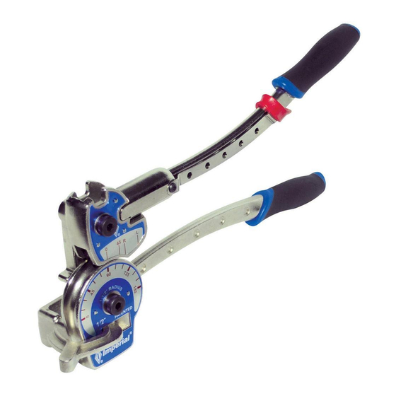
Page 4: Tube Bender Features
The components of the tube bender are named in Figure #1. Figure #1 TurnPro indexing tube benders are available in sizes to bend 1/4, 3/8, and 1/2 in. and 6, 8, 10, and 12 mm OD tubing. The size of the tube bender is indicated on the face of the tube bender near the alignment marks. -
Page 5: Tube Fitting Installation
Fractional Tubing Wall Thickness Table #2 Metric Tubing Wall Thickness Table #3 Tubing Installation When bending tubing, it is important to allow a sufficient length of straight tubing between the shoulder of the tube fitting and the bend. ( See Figure 2) Figure #2 Tables #4 and #5 specify the minimum required lengths for straight tubing leading into a tube fitting for each tubing OD... -
Page 6: Sequential Bend Method
Bend Allowance Tables Table #4 Table #5 Bend Layouts In this section, you will learn methods to plan, measure, and mark tubing. Sequential Bending Method In this method, users measure, mark, then bend each leg of the fabrication in a sequence until the project is completed. The steps are: 1. - Page 7 5. Using the vertex of this bend as the reference market for the next bend, repeat steps 3 and 4 to complete the next bend. 6. For additional bends, use the vertex of the previous bend as the reference mark, repeat steps 3 and 4 for the next bend.
-
Page 8: Offset Bends
Figure #4 Mark the outside of the bend to make the next bend easier to align. Laying Out Offset Bends Offset bends change the centerline of the tubing run to avoid an obstruction. Figure #5 To determine the distand between bend marks in an offset: 1. -
Page 9: Calculating Gain
Example Offset bend angle (E) 45° Offset Dimension (O) 3.50 in . 3.5 x1 .414 = 4.94 in. or approximately 5 in. Figure #6 Adjustment (Gain) Method The Adjustment or Gain Method measures and marks the entire layout for a project prior to bending using adjustment or gain factors. - Page 10 Adjust Method Example Steps (refer to Figure #7) 1. Mark the tubing for the first vertex P1= 3 in. 2. Calculate the second vertex mark by adding the second leg to the first then subtracting gain factor for the first bend.
-
Page 11: Using The Tube Bender
Metric Adjustment Calculations Table #8 Using the Tube Bender Left Reference Bends 90° Bends 1. Swing the indexing handle up so it is above the die. 2. Open the tube lock hook. 3. Place the tube in the groove of the bender die with the reference mark to the left of the tube lock hook. -
Page 12: Bends Greater Than 90
7. Align the vertex mark with the alignment mark that corresponds to the bend angle. For 90° bends align the vertex mark under the "L" as shown in Figure #8. Figure #8 8. Push the tube latch firmly over the tube to secure the tube in the bender die. - Page 13 Figure #10 3. Pull the handle down until the 0 alignment mark meets the desired angle mark. Note: You might have to press 2 or 3 degrees past your target angle to compensate for spring back. (See Figure# 12) Figure #11 Bend Angles Less than 90°...
-
Page 14: Right Reference Bends
For other angles less than 90° estimate where the alignment mark should be then align the vertex mark on the tubing under that alignment mark. For example, an arrow in Figure 13 indicate where the vertex is aligned for a 30° bend. Figure #13 Right Reference Bends Right reference bend are made with the reference mark to... -
Page 15: Change In Plane And Direction
Changes In Plane and Direction When making a bend on a new plane or a new direction, it is helpful to think of a protractor mounted on the tube bender with the 0° at the straight up position as shown. To make our bend, set the tube in the bender such that the previous leg is at the 0°... -
Page 16: Troubleshooting
Troubleshooting... - Page 18 AUTHORIZED DISTRIBUTOR: 8250 Boyle Pkwy Twinsburg, OH 44087-2200 P: +1 330.425.4250 F: +1 330.425.8116 SSPTBPG-001-13A ©2013, SSP Fittings Corp.
Need help?
Do you have a question about the TurnPro and is the answer not in the manual?
Questions and answers