Table of Contents
Advertisement
Quick Links
A013035UA, 502209
MARLIN TECHNOLOGIES INC
1. Introduction
The Cabin Control Display (CCD) is the user interface/controller for the Dynasys Auxiliary Power and Climate Control Unit
(APCCU). The Auxiliary Power Unit (APU) is a self-contained, stand-alone power generator for use with class 8 trucks
which provides both 120VAC power for the CCU as well as 12VDC recharging for the Truck's batteries while in operation.
The Climate Control Unit (CCU) [or HVAC system] provides climate control for the truck bunk. Additional items or
features include optional single duplex 120VAC convenience outlet, optional Power Distribution Center (PDC) with
dedicated circuit breakers. The Dynasys system uses the truck's diesel fuel supply and 12VDC battery source. This
system does not require the usage of the trucks cooling and A/C system. The Dynasys APCCU provides significant fuel
savings, reduction of truck engine wear, reliability, increased driver comforts, and legislative compliance.
The Cabin Control Display mounts inside the truck cabin and provides the user with convenient interface controls for
cabin temperature, monitor APU engine activities and outputs, Service History, Active/Historical Alarm Faults, and
Automatic Starting Controls. On the back of the CCD, the 6-pin connector houses the cabin temperature sensor and the
12-pin connector is for Power and a CAN-Bus connection to the APCCU control module. This CAN-Bus connection is the
communication link between the Display and Controller but also allows for the system to be updated with any future
software updates and monitor the APCCU's full performance status for diagnostic purposes.
2. Display Unit
The following sections describe how the Cabin Control Display controls for the Inactive Screen, Main Screen, Menu
Screen, Engine Status Screen, Service Screen, Active Alarms Screen, Alarm History Screen, Password & Secure Settings
Screen, and About Screen.
USER GUIDE
CREATED
CHECKED
APPROVED
ECN
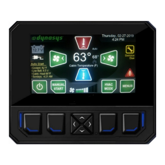
The Cabin Control Display is the interface for the operator to
control the Dynasys APCCU. There are 8 buttons on the
display. All of them are soft buttons meaning that their
functionality will vary based on which screen you are on or
what conditions exist so a quick visual guide at the bottom of
the screen indicates what the button will do for each screen.
The 4 navigation buttons in the middle are generally used to
move up/down/left/right on the screen most of the time. If
their functionality is not for navigating the screens, then that
alternate functionality will be displayed for the operator.
PAGE 1 OF 17
B. BERTOLASI
DATE 02/25/2020
S. JOHNSON
DATE 03/27/2020
S. JOHNSON
DATE 03/27/2020
13026E
DATE 01/24/2019
Advertisement
Table of Contents

Summary of Contents for Marlin Technologies Cabin Control Display
- Page 1 DATE 01/24/2019 1. Introduction The Cabin Control Display (CCD) is the user interface/controller for the Dynasys Auxiliary Power and Climate Control Unit (APCCU). The Auxiliary Power Unit (APU) is a self-contained, stand-alone power generator for use with class 8 trucks which provides both 120VAC power for the CCU as well as 12VDC recharging for the Truck’s batteries while in operation.
- Page 2 A013035UA, 502209 USER GUIDE PAGE 2 OF 17 MARLIN TECHNOLOGIES INC 13026E DATE 01/24/2019 3. Display – Inactive Screen The Inactive Screen is displayed when the Power button is pressed on the Main screen or from power- up of the system. All functions are disabled in Inactive Mode (except for Low Battery AutoStart).
-
Page 3: Button Operation
A013035UA, 502209 USER GUIDE PAGE 3 OF 17 MARLIN TECHNOLOGIES INC 13026E DATE 01/24/2019 Main (Active) Screen – General Status Indicators Service Indicator – The indicator is normally in GRAY and shows how many hours until the next service is due. -
Page 4: Screen Saver
A013035UA, 502209 USER GUIDE PAGE 4 OF 17 MARLIN TECHNOLOGIES INC 13026E DATE 01/24/2019 Navigation Buttons – Press Left(Decrease) or Right(Increase) to change the Users Fan Speed setting. Press Up(Increase) or Down(Decrease) to change the Setpoint Temperature (displayed in the center of the screen) for the active HVAC mode, when done there is a 5 second delay for the setting to be locked HVAC Button –... -
Page 5: Settings Screen
A013035UA, 502209 USER GUIDE PAGE 5 OF 17 MARLIN TECHNOLOGIES INC 13026E DATE 01/24/2019 7. Engine Status Screen The Engine Status Screen gives the operator real-time feedback of the APU Engine sensors, the Generator output Status, and the outputs controlling the APU. This is just a status screen so no actions can be taken. -
Page 6: Service Screen
A013035UA, 502209 USER GUIDE PAGE 6 OF 17 MARLIN TECHNOLOGIES INC 13026E DATE 01/24/2019 To gain access to the settings in the Secured Settings, the Service Technician needs to enter a valid 4-digit PIN# into the display. Use the Navigation buttons to select each value and press the enter button(far right). - Page 7 A013035UA, 502209 USER GUIDE PAGE 7 OF 17 MARLIN TECHNOLOGIES INC 13026E DATE 01/24/2019 Service Reminders Total Operating Hours 1000 2000 3000 4000 5000 6000 Page 1 Change Engine Oil & Filter Check Belts, Hoses, & Water Separator Check for Leaks & Loose Parts Check for Unusual Noise &...
- Page 8 A013035UA, 502209 USER GUIDE PAGE 8 OF 17 MARLIN TECHNOLOGIES INC 13026E DATE 01/24/2019 11. Alarm History Screen The Alarm History Screen shows a history of faults that have occurred along with a timestamp of when the fault occurred up to a total of 20 faults. General...
- Page 9 A013035UA, 502209 USER GUIDE PAGE 9 OF 17 MARLIN TECHNOLOGIES INC 13026E DATE 01/24/2019 14. All saved values The following is a list of all values stored by the APCCU. They are saved when the system is put Inactive. Main...
- Page 10 A013035UA, 502209 USER GUIDE PAGE 10 OF 17 MARLIN TECHNOLOGIES INC 13026E DATE 01/24/2019 Main Sub- Sub- Menu Menu 1 Menu 2 R# Parameter Name Default Units Notes 67 Settings Secured(PIN#) View/Chng:Pg3: v6 EngSpd - Started RPM 8000 68 Settings Secured(PIN#) View/Chng:Pg3: v7...
- Page 11 A013035UA, 502209 USER GUIDE PAGE 11 OF 17 MARLIN TECHNOLOGIES INC 13026E DATE 01/24/2019 16. Operation of the Auto-Start Functions The APCCU Auto-Start Functions are not allowed to operate when the System is Inactive (with the exception of Low Battery). While the system is Active and the Auto-Start Functions are enabled they will operate per the following list. All Auto-Start functions can be aborted by putting the System into the Inactive State or activating E-STOP.
- Page 12 A013035UA, 502209 USER GUIDE PAGE 12 OF 17 MARLIN TECHNOLOGIES INC 13026E DATE 01/24/2019 20. Engine Controls The APU Engine is controlled by the APCCU. In Manual Control the operator can press the Engine “Manual Start” button to turn the APU Engine On and the Engine “Manual Stop” button to turn the APU Engine Off. The APU Engine can also be started by one of the Auto-Start functions and after running its pre-determined time will turn the APU Engine back off.
- Page 13 A013035UA, 502209 USER GUIDE PAGE 13 OF 17 MARLIN TECHNOLOGIES INC 13026E DATE 01/24/2019 21. Troubleshooting Tips CCD is blank Screen might be in low power mode. Watch for the side LEDs to flash briefly • every 5 seconds indicating it’s still active but in low power mode. Press the down button to wake the display up.
- Page 14 A013035UA, 502209 USER GUIDE PAGE 14 OF 17 MARLIN TECHNOLOGIES INC 13026E DATE 01/24/2019 (Engine Run Failure) If also Engine Speed Error – 120VAC Input is not detected. Check Engine, • Generator and cabling for 120VAC feed to the APCCU.
- Page 15 A013035UA, 502209 USER GUIDE PAGE 15 OF 17 MARLIN TECHNOLOGIES INC 13026E DATE 01/24/2019 HVAC Fan won’t turn on The APU must be running or on Shore Power for the HVAC fan to run. Start the • APU or connect Shore Power.
- Page 16 A013035UA, 502209 USER GUIDE PAGE 16 OF 17 MARLIN TECHNOLOGIES INC 13026E DATE 01/24/2019 22. Status Indicator Lights on the Control Board The APCCU controller as two LED’s in the lower left corner that indicate the general status of the board. While the APCCU is running at full power the LED’s will be on constantly. If the APCCU goes to low power mode, the LED’s will flash briefly every 5 seconds to continue to...
- Page 17 A013035UA, 502209 USER GUIDE PAGE 17 OF 17 MARLIN TECHNOLOGIES INC 13026E DATE 01/24/2019 Other Application Notes: There’s a 1 second delay from powerup before functionality starts (able to reflash before program locks-up) • There’s a 60 second delay from powerup for all Battery Monitoring conditions (faults & autostarts) •...
Need help?
Do you have a question about the Cabin Control Display and is the answer not in the manual?
Questions and answers