Advertisement
Quick Links
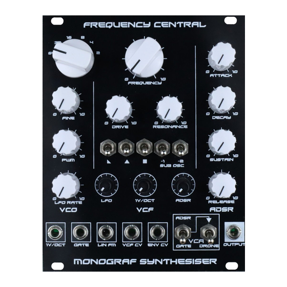
Frequency central
Monograf synthesiser
Monograf is a fixed signal path monophonic synth voice with many unique features, including a
number of patch points for flexibilty within a modular setting. Our aim was to design the simplest
full featured and good sounding single VCO synth within as small a space as possible, while offering a
broad sonic palette and fast setup times. Monograf includes the following elements:
•
Onboard LFO for PWM,
and onboard sub osc for
thick and juicy synth
lines
•
Super stable AS3340
based VCO featuring
sawtooth, triangle and
square waveforms, as
well as rotary switch
control of octaves and
an onboard LFO for
PWM. Features highly
accurate 1V/octave
tracking, as well as
extenal CV control of
linear FM.
•
Sub oscillator featuring
-1 octave and -2 octave
square waveforms. Add
a big bottom to your
sound.
•
5 toggle switches for
fast waveform
selection, allows for
super quick changes.
Additionally, the
triangle waveform is
routed directly to the
VCA, bypassing the VCF, to maintain a rumbling low end with higher resonance settings, this
is a little known modular trick which was practised by the ancients (!?).
•
12dB/octave OTA lowpass VCF based upon ARP Odyssey Mk1 'whiteface'. A very
characterful VCF with cutting resonance whose audio inputs can be driven into clipping via a
dedicated Drive control. The chosen level of drive can have a profound effect over the
character of the filter, and heavy drive will saturate the input while simultaneously reducing
resonance. Cutoff frequency can be controlled manually, from the LFO, from the ADSR,
normalised from a 1V/oct source, or from an external CV.
•
Vintage ARP style VCA with gated/ADSR/drone options via two toggle switches.
•
AS3310 based ADSR for super snappy envelopes. CV control of envelope output is available
for velocity controlled dynamics etc.
Build documentation for:
Advertisement

Summary of Contents for Frequency Central Monograf
- Page 1 Build documentation for: Monograf synthesiser Monograf is a fixed signal path monophonic synth voice with many unique features, including a number of patch points for flexibilty within a modular setting. Our aim was to design the simplest full featured and good sounding single VCO synth within as small a space as possible, while offering a broad sonic palette and fast setup times.
- Page 2 Monograf features a 3 PCB set: • Main PCB • Control PCB • Octave switch PCB The Main PCB contains the main elements of the synthesiser: VCO, VCF, VCA, ADSR, PWM LFO, and power section. Each section is labelled appropriately.
- Page 3 Bill of Materials 100pF x 2 AS3310 x 1 A100K x 1 100R AS3340 x 1 470R 1nF x 3 LM13700 x 2 B100K x 9 820R 10nF x 4 22nF x 1 CD4024 x 1 B100K x 3 33nF x 1 TL072 x 4 these)** 100nF x 3...
- Page 4 Main PCB assembly 1. Solder all resistors and diodes 2. Solder all IC sockets 3. Solder all non-electrolytic capacitors 4. Solder all 3 voltage regulators 5. Solder all transistors 6. Solder all trimmers 7. Solder the power header – if you’re using box type, observe correct polarity 8.
- Page 5 Control PCB 1. Solder all resistors 2. Solder both IC sockets 3. Solder the trimmer 4. Place the 10 metal shaft pots on the PCB, and fold over the mounting tabs of the pots at the rear of the PCB, then place the panel over them. This will assure that they are correctly positioned.
- Page 6 Octave Switch PCB 1. Solder the 1P12T rotary switch. 2. Cut the plastic flange off. Final Assembly 1. Mount the Control PCB onto the panel. Tighten all mounting nuts. 2. So, the 1P12T rotary switch needs to be adjusted to be a 1P6T rotary switch. Remove the mounting nut and the washer, below them you will find another washer with a small flange at 90°, the inner part of the switch has a number of slots, drop the flange into the slot marked 6, then waggle the switch to make sure you’re getting 6 positions.
- Page 7 Calibration • 4K7 Octave (Control PCB): Set the octave switch to it’s highest octave position (2’) and adjust trimmer until you get a reading of 7.5V at the Test on the octave rotary switch daughter board. • 10K Scale (VCO): This trimmer sets the 1V/oct tracking of the VCO, and it’s really worth spending some time to get it right.
Need help?
Do you have a question about the Monograf and is the answer not in the manual?
Questions and answers