
Subscribe to Our Youtube Channel
Related Manuals for Gree GIE-ADC12K5E


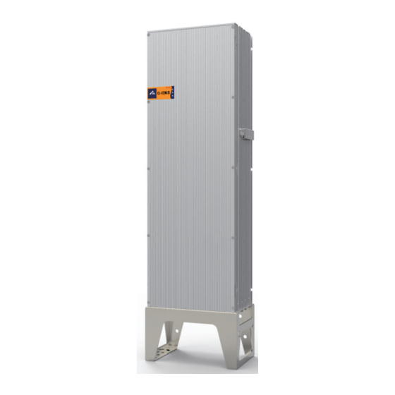
Summary of Contents for Gree GIE-ADC12K5E
- Page 1 Owner's Manual Original Instructions Intelligent Converter Intelligent Converter Models: GIE-ADC12K5E...
- Page 3 Preface IMPORTANT SAFETY INSTRUCTIONS SAVE THESE INSTRUCTIONS – This manual contains important instructions for Model(s) FULAGDA series that shall be followed during installation and maintenance of the power conversion system. CAUTION – To reduce the risk of fire, connect only to an AC line circuit provided with 40/45 amperes maximum branch-circuit overcurrent protection in accordance with the National Electrical Code, ANSI/NFPA 70.
- Page 5 If the user does not follow the method the manufacturer specifies to use the converter, the converter protection measure may fail. The converter must be maintained or repaired by professional personnel. In case of any damage, contact local maintenance center of GREE.
-
Page 7: Table Of Contents
Contents 1. COMPONENTS AND ACCESSORIES ......................1 2. PACKING LIST ............................1 3. OPERATION METHOD ..........................1 4. INDICATORS AND MEANINGS ........................2 5. SIZE AND HOLES ............................3 6. TRANSPORT, STORAGE AND INSTALLATION ..................... 3 7. WIRING ..............................7 7.1 CONVERTER TERMINALS ........................ -
Page 9: Components And Accessories
Intelligent Converter 1. Components and Accessories Status indicator Electric box Terminal Mounting base 2. Packing List Main unit Converter 1 set Printout Manual 1 copy Printout Warranty card 1 copy Printout Certificate 1 copy Printout Barcode 1 copy Printout Installation confirmation receipt 1 copy Printout Packing list... -
Page 10: Indicators And Meanings
Intelligent Converter 4. Indicators and Meanings COM: Yellow communication indicator. Indicates device IP addresses. They are coded and displayed following the Morse code and display interval in the table below. IP addresses are displayed as 00 to 99 cyclically. RUN: Green running indicator. -
Page 11: Size And Holes
Intelligent Converter 5. Size and Holes Maximum size: 307 mm X 204.5 mm X 1109 mm (D X W X H) Weight: 45 kg Hole sizes are shown in the following figure: 6. Transport, Storage and Installation Transport Load and unload the converter with caution to avoid deformation, break or other problems. Storage If the converter is not put into use immediately, store it following the requirements below: 1. - Page 12 Intelligent Converter Installation Installation precautions 1. Ensure that the installation position is firm enough to support the weight of the converter and force generated by external vibration. 2. Ensure that the installation position and height of the converter facilitate wiring, operation, and maintenance.
- Page 13 Intelligent Converter 7. The relative humidity of the installation place should not exceed 95%; otherwise, vapor may corrode the converter and cause damage to internal components. 8. It is of vital importance to ensure good ventilation of the converter. Do not install the converter in a sealed box;...
- Page 14 Intelligent Converter Bolt specifications Screw Position Specification Screw Qty. Torque Mounting base bottom M8*60 20N.m The DC and AC output circuits are isolated from the enclosure and that system grounding, if required by Section 250 of the National Electrical Code, ANSI/NFPA 70, is the responsibility of the installer.
-
Page 15: Wiring
Intelligent Converter 7. Wiring Warning 1. All wiring steps must comply with electric standards of a country or region where the installation takes place. 2. Follow these rules: rules related to input power grid; safety instructions related to PV strings. 3. - Page 16 Intelligent Converter Total circuit breaker Min. sectional area of Recommended conductive capacity(A) grounding wire(mm wire(Sectional area mm quantity) 6.0×4 The current protection value recommended for the AC output is the maximum value calculated based on the rated current. In other cases, the current is determined based on actual need.
-
Page 17: Converter Terminals
Intelligent Converter 7.1 Converter Terminals COM port AC power port PV input port channels 1~2 DC output port PV input ports: PV1+ and PV1-: PV input port channel 1, connected according to positive and negative polarities, voltage: < 1000V DC PV2+ and PV2-: PV input port channel 2, connected according to positive and negative polarities, voltage: <... -
Page 18: Converter Output Dc Bus Terminals
Intelligent Converter CAN: CAN communication port, used for data exchange between multiple converters. This port is optional. ETH: Ethernet communication port, used for data exchange between the converter and energy information management system G-IEMS. This port is optional. USB: USB disk port, used for commissioning the converter. Converter Terminal Specifications Terminal Converter Terminal Socket... -
Page 19: Converter Pv Input Cable Connection
Intelligent Converter Wire Wire Circuit Tightening torque (N•m) Wire Temperature rating size(AWG) type DC output 10AWG Copper 90degC The following table lists specifications of optional wires: End A (Converter Terminal) Recommended Wire End B (Electric Device Terminal) Markings Terminal Color Specification Markings Terminal... - Page 20 Intelligent Converter PV Input Terminals Terminal Converter Terminal Socket Match Wire Terminal Plug Type Silkscreen Code Model Code Name Name Mould case Mould case connector 44040024 connector 4404002401 2-1971914-1 PV1- 2270040-2 Match PV2- Terminal 4202018903 4202018902 Terminal 1971857-4 1971858-4 Mould case Mould case connector 4404002403 connector...
-
Page 21: Converter Ac Wiring
Intelligent Converter DC negative terminal DC negative terminal Plug Core DC connector (negative) DC positive terminal Plug DC positive terminal Core DC connector (positive) PV Terminal Connection with Converter Insert PV input cables equipped with connectors into the PV- and PV+ terminals at the bottom of the converter accordingly. -
Page 22: Remover Operation Method
Intelligent Converter 8. Remover Operation Method If the converter needs disassembly or maintenance, insert a remover (as shown in ①) into a hole to remove the connector. If a DC connector needs disassembly, use a remover (as shown in ②) to tighten or loosen a nut. -
Page 23: Product Models And Technical Specifications
UL 1741 IEEE 1547 Note: The product can work in different modes by configuring Grid voltage. Manufacturer: GREE Energetic & Environmental Technologies Co., Ltd. of Zhuhai Made in China Implementation standards: UL 1741 and IEEE 1547. In case of any change in performance parameters, the data on the nameplate prevails. - Page 24 Intelligent Converter ELECTRICAL RATING Other ratings Max. output fault current (A) / duration (ms) 151.2A rms / 406.8 peak /1.348 ms Max. utility backfeed current to PV array (A) Line Synchronization Characteristics /In-rush Method 2 current Limits of accuracy of voltage measurement Limits of accuracy of frequency measurement +/- 0.1 Hz Limits of accuracy of time measurement...
-
Page 25: Pv System Installation Project
Intelligent Converter 11. PV System Installation Project A PV system installation project consists of PV rack and PV cell component installation, cable laying, and power distribution device installation. You are advised to follow the steps below. PV racks and components must be accepted by the buyer and a professional supervision unit before they can be installed.
Need help?
Do you have a question about the GIE-ADC12K5E and is the answer not in the manual?
Questions and answers