Advertisement
Quick Links
PARTS LIST
Acrylic extrusion
Acrylic extrusion
Acrylic tube
Element
Solar motor RF 270
Distance tubes
Brass rod
Silicon tube
PVC-tube *)
Machine screws
Machine screws
Nuts
Drinking straw with bend
*) Please Note:
If you use a drinking straw as a pipe the holder for the tube must be drilled out to 5m dia (Plates C und B).
E111471#1
111.471
P r e m i u m - L i n e
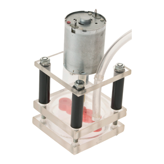
" W a t e r p u m p "
The OPITEC range of projects is not intended as play toys for
young children.They are teaching aids for young people
learning the skills of Craft, Design and Technolo- gy.These
projects should only be undertaken and tested with the
guidance of a fully qualified adult. The finished projects are
not suitable to give to children under 3 years old. Some
QUANTITY
1
2
1
1
1
4
1
1
1
4
2
4
1
Necessary tools
Fresaw or hacksaw
Pillar drill
Screwdriver
Allen keyl M3
Drills ø3, 3,5, 6, 6,5 mm
Scriber
Emery cloth, file
Oil for drilling acrylic
All purpose
Hammer
Please Note
parts can be swallowed. Dan- ger of suffocation!
SIZE (mm)
Description
42x42x3 Motor holder
42x42x5 Housing 1+2
ø 40x7 Turbine housing
30 Turbine
3-12 Volt Drive
ø7x25 Distance pieces
ø3x25 Axles
ø3x20 Coupling
ø6x1000 Water tube
M3x50 Joining
M3x6 Motor fixing
M3 Fixings
210x5 Water pipe
PART -Nr.
1
2
3
4
5
6
7
8
9
10
11
12
13
1
Advertisement

Summary of Contents for Opitec 111.471
- Page 1 All purpose Hammer Please Note The OPITEC range of projects is not intended as play toys for young children.They are teaching aids for young people learning the skills of Craft, Design and Technolo- gy.These projects should only be undertaken and tested with the guidance of a fully qualified adult.
- Page 2 INSTRUCTIONS General decscription The Premium-Line Water pump will lift a large volume of water and functions from 3 to 12 Volts. Place in the pump in a flat transparent container of water with water covering the turbine housing but not touching the motor. The outlet water pipe can be arranged so the pumped water flows back into the container.
- Page 3 INSTRUCTIONS File the brass rod flat on either end and insert it with a hammer in the middle hole of the red turbi- Dia. 3 Assembling the water pump 1. Strar with the acrylic plate (A) and insert the 4 machine screws (10) up through the holes in the cor- ners, as shown in diagram 3.
- Page 4 Dia.9 INSTRUCTIONS 7. Place the nuts (12) on the fixing screws and then tighten (see dia. 9) Note Do not overtighten the nuts so that the turbine housing ( A+B) otherwise the housing can deform and the pressure escape sideways. Make sure the turbine is central in the housing ! Dia.
-
Page 5: Exploded Diagram
INSTRUCTIONS EXPLODED DIAGRAM Arylic sheet Scale 1:1 Thickness: 3mm Thickness: 5mm Thickness: 5mm E111471#1...
Need help?
Do you have a question about the 111.471 and is the answer not in the manual?
Questions and answers