
Summary of Contents for SilverNet 7 Series
- Page 1 ERIES NDUSTRIAL IGABIT NMANAGED SWITCHES SIL 73204P SIL 73208P User Manual V1.2 www.silvernet.com...
-
Page 2: Table Of Contents
Technical parameters ........................ 9 Standards ..........................10 Warnings ..........................10 Troubleshooting ........................11 Responsibility Note ........................11 Warranty ..........................11 Contact SilverNet ........................11 Copyright Information ......................11 Other SilverNet Products ......................12 Network Switches User Manual Table Of Contents... -
Page 3: Introduction
NTRODUCTION The SilverNet Series 7 Industrial Gigabit PoE+ Managed Switches are reliable, high performance, high specification and cost effective Managed industrial switches suitable for industrial network operations. The un-managed switches require no configuration and instantly operate as soon as you power them up. -
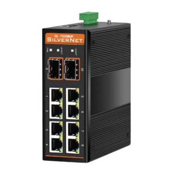
Page 4: The Panels And Led Indicators
ANELS AND INDICATORS SIL 73204P and SIL 73208P Mark Name Function Power LED “On”: Power is on and normal System LED “On”: System is on and normal “On”: Fibre connection is present SFP Port “Blinking”: Data being transmitted Yellow LED “On”: PoE connection is present Yellow LED “Blinking”: Data being transmitted RJ45 Ports Green LED “On”: Ethernet connected at 1000M... -
Page 5: Installation
NSTALLATION DIN- RAIL INSTALLATION Pic 1 Pic 2 The DIN-rail installation is based on Pic 1 and Pic 2. MOUNTED INSTALLATION The wall mount kit is fixed to the back of the switch. Remove and re-attach the wall mounting kit as shown in the image above. Attach the switch and bracket to the wall using appropriate screws. -
Page 6: Power
OWER The input terminal of the switch is for 6 PIN plug type terminals, V1+ and V1- is for power supply 1 (PWR1), V2 + and V2- is for power supply 2 (PWR2) and GND for the earthing terminal, as shown in image below.. The input voltage range for power 1 and power 2 is 12VDC ~ 56VDC,V1+, and V2+ are positive, V1- and V2- are negative. -
Page 7: Copper Cable Connection
OPPER CABLE CONNECTION RJ45 TANDARD CONNECTOR There are 8 wires on a standard UTP/STP cable, and each wire is colour coded. The following shows the pin allocation and colour of a straight through cable and crossover cable: Network Switches User Manual Copper cable connection... -
Page 8: Fibre Cable Connection
IBRE CABLE CONNECTION CCESSORIES 1Gbps Fibre transmission Part Code Description SIL-SFP0-01-25-X850-0-5D 1G Multimode 850nm SFP, 550m SIL-SFP0-01-25-X131-10XD 1G Singlemode 1310nm SFP, 10km SIL-SFP0-01-25-X131-40XD 1G Singlemode 1310nm SFP, 40km SIL-SFP0-01-25-X155-80XD 1G Singlemode 1550nm SFP, 80km 1Gbps BiDi SIL-SFP0-01-25-B131-10XD 1G SM 1310nm TX FP 10km with DDM, 1550nm RX SIL-SFP0-01-25-B155-10XD 1G SM 1550nm TX FP 10km with DDM, 1310nm RX SIL-SFP0-01-25-B139-10XD... -
Page 9: Technical Parameters
ECHNICAL PARAMETERS Power supply Input voltage: 12V~56V (redundant dual power) PSE Power: 0~30W POE Pin: 1/2+,3/6- Copper Port Connector: RJ-45 connector Data Rate: 10/100MbpsAuto, 10/100/1000Mbps Auto Twisted Pair cable: Cat5 UTP cable Transmission distance: 100 metres Fibre Port Connector: SC (default), FC/ST/SFP (optional) Data Rate: 155Mbps,1.25Gbps Fibre Type: SM 9/125μm,MM 50/125μm、62.5/125μm Transmission distance: 20km ~ 120km... -
Page 10: Standards
TANDARDS EMI FCC Part 15 Subpart B Class A EN61000-4-2(ESD) EN61000-4-3(RS) EN61000-4-4(EFT) EN61000-4-5(Surge) EN61000-4-6(CS) EN61000-4-8 EN61000-4-11 IEC60068-2-27 IEC60068-2-32 IEC60068-2-6 EN60950-1 ARNINGS This product is only suitable for indoor applications. Ensure that the dust caps are placed over the Fibre interface connectors when not in use. Do not stare directly into the fibre transmitter as this is very dangerous and can cause serious damage to your eyes. -
Page 11: Troubleshooting
3. If you use a Power Supply that is not provided by SilverNet and the device is damaged, then this is not covered under the product warranty. -
Page 12: Other Silvernet Products
THER ILVER RODUCTS Pro Range Industrial Network Transmission Intelligent Wi-Fi Solutions Industry Leading Technical Support Network Switches User Manual Other SilverNet Products...
Need help?
Do you have a question about the 7 Series and is the answer not in the manual?
Questions and answers