Table of Contents
Advertisement
DSAT-300 USER GUIDE
DOCUMENT REVISION: 1.015
(DOC0594)
Applies to: DSAT-300 Mod None Firmware Version 00.01.10+
NOTE: Access the latest revision at
Oct 31, 2016
SKYTRAC Systems Ltd.
Tel. +1 250 765-2393
Fax +1 250 765-3767
Web: www.skytrac.ca
Email:
techsupport@skytrac.ca
© SKYTRAC Systems Ltd. All Rights Reserved.
www.skytrac.ca/support
Advertisement
Table of Contents

Related Manuals for Skytrac DSAT-300 Series

Summary of Contents for Skytrac DSAT-300 Series
- Page 1 Applies to: DSAT-300 Mod None Firmware Version 00.01.10+ NOTE: Access the latest revision at www.skytrac.ca/support Oct 31, 2016 SKYTRAC Systems Ltd. Tel. +1 250 765-2393 Fax +1 250 765-3767 Web: www.skytrac.ca Email: techsupport@skytrac.ca © SKYTRAC Systems Ltd. All Rights Reserved.
- Page 2 DSAT-300 USER GUIDE DOCUMENT REVISION HISTORY PAGE DESCRIPTION DATE AUTHOR 01.000 Initial Release 18 Dec 2009 01.001 Added EMI Test 14 Jan 2010 01.002 Added storage detail 15 Jan 2010 01.003 BlackBerry OS Info updated 21 Jan 2010 01.004 Power requirements update 22 Jan 2010 01.005 Storage Temp update...
- Page 3 SKYTRAC Systems for an RMA #. Once an RMA # has been obtained, the unit should be returned to: SKYTRAC Systems will provide the return address to ship the equipment to at the time of issuing the RMA #.
-
Page 4: Table Of Contents
DSAT-300 USER GUIDE CONTENTS ABOUT THIS DOCUMENT ..........................5 Purpose ................................5 Glossary of Terms and Abbreviations ......................5 INTRODUCTION ............................. 5 Description of Equipment ..........................5 Features ................................6 DSAT-300 ACTIVATION AND CONFIGURATION ..................8 Unit Activation ..............................8 AFF Pricing Plan .............................. - Page 5 DSAT-300 USER GUIDE ANTENNAS ..............................18 13.1 External Antenna Install ..........................18 13.2 Connections ..............................19 13.3 Portable Antennas ............................19 13.4 TSO Combination Antenna ..........................20 FIRMWARE UPGRADE ..........................21 14.1 Required Hardware ............................21 14.2 USB Driver ..............................21 14.3 Determining the Correct Com Port ........................
-
Page 6: About This Document
Iridium® Low Earth Orbit (LEO) satellites. Present position and selectable operational messages from the aircraft can be displayed on any computer with Internet access and SKYTRAC software. Position reporting intervals are user defined and configurable within the Hardware Management section of SkyWeb. -
Page 7: Features
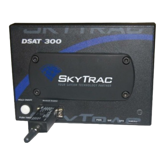
DSAT-300 USER GUIDE DSAT- DSAT- 300E 300I Antenna Optical Push Integrated Bluetooth Connection Sensor Butto Antenna Connection DSAT-300E and DSAT-300I The following lists the different DSAT-300 packages: DSAT-300I with the Integrated TSO GPS/Iridium Dual Antenna DSAT-300E with Portable GPS and Iridium Antennas ... - Page 8 DSAT-300 USER GUIDE NOTE: CAN ONLY BE SET VIA BLACKBERRY WITH STS MESSENGER INSTALLED AND CONNECTED VIA THE BLUETOOTH OR WI-FI ADAPTER. Document Rev. 1.015 DOC0594 Page 7 of 28 Restricted Proprietary and Confidential Information...
-
Page 9: Dsat-300 Activation And Configuration
3.1 UNIT ACTIVATION Prior to first use the unit will need to be activated. The user’s SKYTRAC Program Manager will normally do this using SkyWeb. By completing ‘Step 2’ in the SkyWeb Hardware Management section, they can activate the unit with the Iridium network. -
Page 10: Emi Test
DSAT-300 USER GUIDE 4 EMI TEST As with any electronic equipment, portable or installed, it is ultimately up the user to ensure there is no interference with existing aircraft electronic systems. Please reference EMI/RFI Test Report DOC0593 Rev 01.000 or latest revision for testing procedures. -
Page 11: Powering The Dsat-300
5.1.1 BATTERY PRECAUTIONS NOTE: The battery precautions are contained in the Panasonic_LiIon_Precautions document which is available via the ‘Support link at www.skytrac.ca. However please note the following storage recommendations: Document Rev. 1.015 DOC0594 Page 10 of 28 Restricted Proprietary and Confidential Information... -
Page 12: Operation From Aircraft Mains Power
DSAT-300 USER GUIDE The batteries should be stored at room temperature, charged to about 30 to 50% of capacity. It is recommended that batteries be charged about once per year to prevent overdischarge. Any form of storage other than the battery manufacturers recommended storage method can decrease battery service life. -
Page 13: Dsat-300 Modes
DSAT-300 USER GUIDE 6 DSAT-300 MODES 6.1 NORMAL MODE (A/C MAINS OR BATTERY) The DSAT-300 ‘Normal Mode’ is for position reporting and/or messaging via BlackBerry/iPhone/Android and additional Bluetooth / Wi-Fi adapter. The unit will be operating on battery power alone or can have wired power connected to recharge the batteries whilst in operation. -
Page 14: Led Indicator Lights
DSAT-300 USER GUIDE 7 LED INDICATOR LIGHTS There are four one-color LEDs on the side of the DSAT-300. Their brightness level is governed by the optical sensor on the unit. This will cause the LEDs to automatically adjust dim to bright depending on the ambient light conditions. The information indicated by the LEDs will depend what mode the unit is in at the time. -
Page 15: Sat - Amber
DSAT-300 USER GUIDE SAT – AMBER 7.2.2 (Normally OFF during operation) In this mode the LED is primarily used to indicate a communication problem such as: Loss of communication with the Iridium Satellite network Position reports or messages are queued in the DSAT-300 ... -
Page 16: Recharge Mode
NOTE: Battery removal instructions are contained in the Battery Pack Removal Instructions (DOC 0595) available from www.skytrac.ca, however please be aware of the following: Except when it is in Emergency Mode, the DSAT-300 will automatically shut down when the remaining capacity reaches a critically low level and further drain could permanently damage the batteries. -
Page 17: Push Button
DSAT will send ‘Message rejected, Inbox is full’ to the originator. 10 LOGGING The DSAT-300 will automatically log and store the latest position data, unprocessed GPS and battery health data and error logs. This data can be retrieved by SKYTRAC Systems only. Document Rev. 1.015 DOC0594... -
Page 18: Factory Reset
DSAT-300 USER GUIDE 11 FACTORY RESET NOTE: A factory reset is not normally required to be performed by users. All configuration parameters can be factory reset (returned to default values) by creating a jumper connected between pin 4 and 5/A1 (GND) of the power connector (see Section 15.1). This will reset the unit to factory default. This reset can only be detected and performed in the power up processing sequence, to avoid any potential accidental reset during operations. -
Page 19: Antennas
DSAT-300 USER GUIDE DSAT-300I with Parani SD200 fitted Notes: The DSAT-300 can only communicate with a single mobile device at one time The DSAT-300 will not transition into sleep mode if the Bluetooth / Wi-Fi device is active ... -
Page 20: Connections
The two antennas must be installed at least 18 inches from one another in a location that has a clear view of the sky. SKYTRAC Systems also recommends that the cable length for each cable be no more than the provided 7.5 feet. -
Page 21: Tso Combination Antenna
The DSAT-300E can also be utilized with a combination, active L1 GPS/Passive low profile, molded radome, Iridium antenna (P/N:STS0021). This recommended system antenna is only available directly from SKYTRAC Systems Ltd and is permanently installed on the outside of the aircraft. Please contact SKYTRAC Systems to discuss the feasibility of using an alternate antenna if required. -
Page 22: Firmware Upgrade
DSAT-300 USER GUIDE 14 FIRMWARE UPGRADE The USB programming port is used to install new or revised firmware in the DSAT-300. The DSAT-300 will go into programming mode automatically whenever the USB cable is connected and the DSAT-300 is powered on or charging. - Page 23 DSAT-300 USER GUIDE Scroll to the bottom of the page and select Device Manager: Document Rev. 1.015 DOC0594 Page 22 of 28 Restricted Proprietary and Confidential Information...
- Page 24 DSAT-300 USER GUIDE Expand the “Ports (COM & LPT)” section on the right. The com port that the USB cable is using will be listed there. If multiple USB devices are indicated, disconnecting and reconnecting the USB cable will enable the user to identify the correct one.
-
Page 25: Firmware Upgrade Instructions
DSAT-300 USER GUIDE 14.4 FIRMWARE UPGRADE INSTRUCTIONS Download the new firmware version from the SKYTRAC website (www.skytrac.ca) to the computer. This firmware is called DSAT-300-Rxx-xx-xx.zip (where xx.xx.xx is the Firmware version included in the zip file). Extract the DSAT-300-Rxx-xx-xx.zip file to a directory on the Windows PC. -
Page 26: Technical Details
DSAT-300 USER GUIDE 15 TECHNICAL DETAILS TECHNICAL DETAILS Voltage Requirements 11 to 30 VDC nominal (airplane power) Absolute Maximum Voltage 40 VDC Power Requirements 1 A at 14 VDC, 0.5A at 28 VDC when charging TEMPERATURE RANGE – OPERATIONAL Batteries Installed -20 °C to 60 °C Batteries Removed -30 °C to 60 °C... -
Page 27: Power Connector
DSAT-300 USER GUIDE 15.1 POWER CONNECTOR View of DSAT-300 power interface 15.1.1 PINS PIN # CONNECTION Positive (+) Aircraft power (nominal 12V/28V) Short to ground (Pin 5/A1) to keep unit in charge mode only (no position reports) when powered through power connector Short to ground (Pin 5/A1) to reset unit to factory default (normally not connected) 5/A1... -
Page 28: P/Ns Of Mating Connector (Crimp Version)
DSAT-300 USER GUIDE 15.1.2 P/NS OF MATING CONNECTOR (CRIMP VERSION) MFR P/N DESCRIPTION Conec 3005W1SXK99A10X Conec Connector Shell w/o contacts Conec 132C15019X Conec Crimp signal contact Conec 132C11029X Conec Crimp Power Contact Conec 165X13369X Conec Plastic Back Shell 15.1.3 P/NS OF MATING CONNECTOR (SOLDER CUP VERSION) MFR P/N DESCRIPTION Conec Connector Shell incl. - Page 29 STATEMENT OF CONFIDENTIALITY The information in this document is the property of SKYTRAC System Ltd. herein referred to as SKYTRAC. SKYTRAC submits this document with the understanding that it will be held in strictest confidence and will not be disclosed, duplicated or used, in whole or in part, for any purpose other than the evaluation of the qualifications of SKYTRAC, without prior written consent.
Need help?
Do you have a question about the DSAT-300 Series and is the answer not in the manual?
Questions and answers