Advertisement
Available languages
Available languages
Advertisement
Table of Contents

Subscribe to Our Youtube Channel
Related Manuals for cinq Shift:R Tour

Summary of Contents for cinq Shift:R Tour
- Page 1 SHIFT:R TOUR SHIFT:R ROAD PINION...
- Page 2 Vielen Dank für dein Vertrauen und den Erwerb eines Cinq Produktes. Du hast ein hochwertiges Produkt »Made in Germany« erworben und wir wünschen dir viel Spass damit. Dein Cinq team For English instructions please see page 14.
- Page 3 Der Shift:R für Pinion wurde für den Betrieb an einem Pinion Getriebe der C-Serie entwickelt. Shift:R für Pinion ersetzt die Original Pinion Box und den zugehörigen Drehgriff. Die Shift:R Tour Schalthebel können an geraden Lenkern mit einem Außendurchmesser von 22,2 mm, die Brems-Schalthebel des Shift:R Road an Rennlenkern montiert werden.
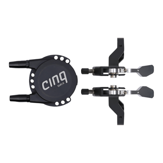
- Page 4 TEILEBEZEICHNUNG Shift:R für Pinion Schaltbox Schaltmechanik Federpaket Externer Schaltmechanismus ICM Technologie (inverse cable mount) externe Zugwechselöffnung Aluminium-Gehäuse aus 6061 Alu Shift:R Tour Schalthebel Shift:R Road Schalthebel Zugeinsteller Zugdurchführung Zugklemme Zugklemme Zugdurchführung...
-
Page 5: Montage
MONTAGE 1a Shift:R Tour Montiere die Schalthebel an Ihrem Lenker in der von dir ergonomisch bevorzugten Stellung durch Anziehen der Inbusklemm- schrauben (max. Anzugsmoment 2,5 Nm). Beachte darüber hinaus unbedingt abweichende Informationen deines Lenkerherstellers bzgl. max. zulässiger Klemmkraft und Montage. Wenn du den Hebel zerlegen musst, so ziehe die TX25 Schraube bei der erneuten Montage mit 5 Nm an und verwende mittelfeste Schraubensicherung. - Page 6 2 Demontiere die original Pinion Schalteinheit mit dem werkseitig montiertem Drehgriff gemäß der Pinion Anleitung. Die drei Befestigungsschreiben werden weiterhin zur Montage der Shift:R für Pinion Schaltbox benötigt. Fixiere diese über die Positionierung- bohrungen mit möglichst geradem Zugverlauf der Schaltzugeingänge. Das benötigte Drehmoment beträgt 1,5 Nm.
- Page 7 Hoch- schalten 4a Shift:R Tour Stelle sicher, dass sich die Zugeinsteller an beiden Schalt- hebeln in mittlerer Stellung befinden. Klemme die Züge am Schalthebel, indem du an dem noch zu langen und überstehenden Teil der Schaltzüge leicht ziehst und diese jeweils per Inbusschrauben fixierst.
- Page 8 4b Shift:R Road Setze die Schaltzugeinsteller an gewünschter Position im Cockpit Bereich ein und führe den Schaltzug durch den Hebel bis zur Zugklemmschraube. Der Schaltzug muss beidseitig leicht vor gespannt sein und dann mit der Zugklemmschraube (4 Nm) fixiert werden. Die Feinjustierung erfolgt über die Schaltzugeinsteller.
- Page 9 Lässt sich ein Hebel ohne bzw. nur mit unzureichender Schaltfunktion durchdrücken, so muss hebelseitig die Schaltzugspannung per Zug- einsteller erhöht werden. Sollte der Verstellbereich des Zugeinstellers hierzu nicht ausreichen, muss der Schaltzug nochmals straffer geklemmt werden (siehe Schritt 4). 6 Kürze die Schaltzüge mit einem Überstand von min. 10 mm und montiere die Zugendkappen.
- Page 10 ZUGWECHSEL Für Fragen zum Getriebe kontaktiere bitte Pinion. Wichtig: Gehe bei einem Zugwechsel unbedingt gemäß nachfolgender Anleitung vor! Öffne keinesfalls die Shift:R Schaltbox, bevor du nicht die Rückstellfedern durch Herausschrauben der Zuggegenhalter entspannt hast! Achte insbesondere darauf, keine Teile durch unsachgemäße Hand habung zu verbiegen, um eine dauerhafte zuverlässige Funktion der Klinkenmecha...
- Page 11 Achtung: Ziehe auf keinen Fall an den Federn, da dies sonst zum Funktionsverlust der Federn führen könnte, sondern ziehe an den Schalt zügen, so dass sich die Rückstellfedern aus der Shift:R Schaltbox einfach entfernen lassen. 2 Ziehe die Zuggegenhalter und Rückstellfedern von den Schaltzügen. 3 Entferne die Abdeckung der Schaltzugöffnung.
- Page 12 4 Wechsle die Schaltzüge. Achte hierbei auf korrekten Sitz der Zugnippel in den Zugaufnahmen. 5 Achte auf den korrekten Sitz der Schalteinheit im Schaltboxgehäuse. Die Nasen des Bajonetts müssen vollständig im dafür vorgesehen Schlitz versenkt sein.
- Page 13 6 Fädele die Rückstellfedern wie auf der nachfolgenden Abbildung zu sehen auf die Schaltzüge. Fädele auch die Zuggegenhalter mit dem Außengewinde voran auf die Schaltzüge. 7 Drücke die Rückstellfedern nacheinander leicht mit den Zug gegenhaltern in das Gehäuse und schraube die Zuggegenhalter mit dem Maulschlüssel in das Gehäuse ein.
- Page 14 ENGLISH Thank you for placing your trust in us and buying a Cinq product. You have just purchased a high quality “Made in Germany” product and we wish you a great time with it. Your Cinq team...
-
Page 15: General Information
The Shift:R for Pinion replaces the original Pinion shift box and shift lever. The Shift:R Tour shift levers can be mounted on flat handlebars with an outer diameter of 22.2 mm, while the Shift:R Road brake levers can be mounted on standard road (drop) handlebars. -
Page 16: Parts List
PARTS LIST Shift:R für Pinion Schaltbox Shift mechanism Return springs External shifting mechanism ICM Technology (inverse cable mount) Cable port 6061 Aluminum housing Shift:R Tour Levers Shift:R Road Levers cable adjuster cable hole set screw set screw cable hole... -
Page 17: Installation
INSTALLATION 1a Shift:R Tour Mount the levers on your handle bar in your ergonomically preferred position. Fasten the hex screws with a maximum clamping torque of 2.5 Nm. If you have to disassemble the lever, tighten the TX25 bolt with a torque of 5 Nm (44 IN LB) and use intermediate bolt adhesive. - Page 18 2 Remove the original Pinion shifting unit with the factoryfitted rotary handle according to the Pinion instructions. The same three mounting bolts which attach the Pinion shift box to the gearbox are used to attach the Shift:R Box to the gearbox. Align the holes in the Shift:R Box to position the shift cables as straight as possible.
- Page 19 4a Shift:R Tour Make sure the cable adjusters are in a middle position before you clamp the shifter cables at the levers to ensure adjustment range later. Slightly pull the cable ends and tighten the cable fastener with an Allen key.
- Page 20 4b Shift:R Road Position the quickadjuster correctly and direct the cable to the cable fixing bolt. The shift cable needs to be slightly preloaded before securing the fixing bolt (4 Nm). Microadjust with the quickadjusters. Cut the cable approx. 10 mm behind the last cable channel and attach the end cap.
- Page 21 6 Cut the shifter cables with a minimum 10 mm overlap and mount the wire end caps. Important notes regarding maintenance: If necessary, especially after a short run-in phase of the Shift:R, repeat step 5. Doing so compensates the initial settling of the cables and end caps. Therefore always pay attention to deficient shifting capacity as well as potential delay of shifting activation.
- Page 22 CHANGING GEAR CABLES For questions about your Gearbox, please contact Pinion. Important: Always follow these instructions when changing your gear cables! Never open the shiftbox before releasing the tension of the return springs by unscrewing the cable retainer first! Pay special attention to not bending parts through improper handling, to ensure a permanently reliable operation of the ratchets.
- Page 23 Warning: Never pull the springs directly, as they could lose their function- ality. Instead, pull the shift cables first, so that the springs can be easily removed from the shiftbox. This procedure will also rotate the cable seats into a suitable position for the gear cable change later on. 2 Remove the cable retainers and return springs from the shift cables.
- Page 24 4 Change the cables, ensuring cable ends are seated correctly in the shift mechanism. 5 Ensure that the shift box internals remain correctly seated in the housing. The tabs of the retention plate must be completely inserted into the slots provided for this purpose.
- Page 25 6 Mount the return springs onto the shift cables as shown in the following picture, followed by the cable retainers with their thread facing towards the shiftbox. 7 Carefully push the return springs with the cable retainers into the housing. Tighten the cable retainer with the wrench using a max.
-
Page 26: Notizen / Notes
NOTIZEN / NOTES... -
Page 28: Garantie / Warranty
Funktion von Shift:R. Von der Haftung ausgeschlossen sind Schäden jedweder Art an den angeschlossenen Geräten. Cinq provides a 12 months limited warranty for defects in manufacturing and functionality of Shift:R. Exempt from liability is any damage to connected devices of all kinds.
Need help?
Do you have a question about the Shift:R Tour and is the answer not in the manual?
Questions and answers