
Summary of Contents for ozQRP CDV
- Page 1 OMPACT IGITAL ONSTRUCTION ANUAL CDV Construction Manual – Issue 3 Page 1...
-
Page 2: Table Of Contents
RIT ......................................23 10.6 VFO Frequency calibration ............................24 10.7 Voltage display calibration ............................24 11 Using the CDV with a superhet rig ........................ 25 12 Optional Attenuator Low pass Filter Board ....................26 12.1 Schematic ................................... 27 12.2 PCB Overlay ..................................27 12.3... - Page 3 Figure 7 CDV used in a superhet rig ........................25 Figure 8 Add-on board options ..........................26 Figure 9 Add-on board schematic ........................... 27 Figure 10 Add-on board PCB overlay ........................27 Figure 11 Attenuator filter board fitted to the CDV ..................30 Change History Date Issue...
-
Page 4: Introduction
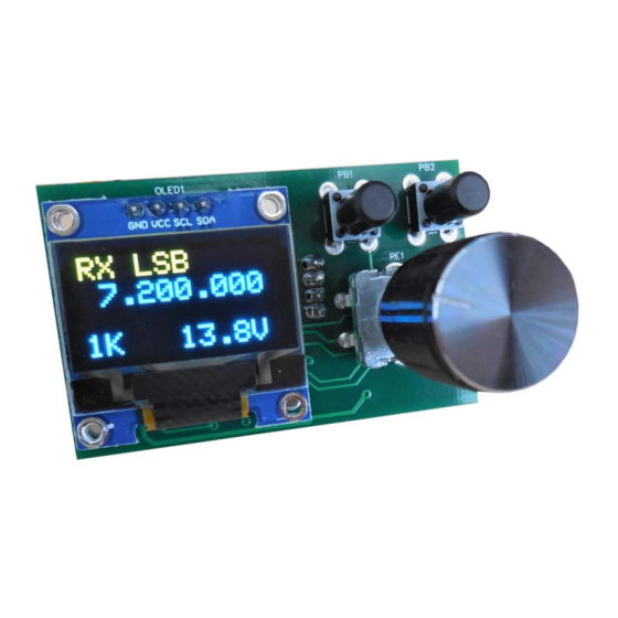
The CDV (Compact Digital VFO) is a variable frequency oscillator suitable for homebrew radio transceivers and general signal generator applications. The CDV is built on a very small PCB that holds all parts including the rotary encoder and OLED display. -
Page 5: Cdv Specifications
16. Output drive level: over 3V pk-pk Hi Z. 2V pk-pk 50 ohms. 17. Output coupling: series capacitor (100nF). 18. Reverse polarity protection: series diode. 19. Input Output connectors: JST 2mm pin pitch polarised connectors. CDV Construction Manual – Issue 3 Page 5... -
Page 6: The Si5351A
PLL frequencies and fractional divider values the clock generator is capable of outputting frequencies from a few KHz up to 200MHz with high accuracy and fine resolution. The CDV uses two PLL and two fractional dividers to provide a fixed output and a variable output. The third output is unused. -
Page 7: Circuit Description
C9 and C10 help limit encoder switch bounce. The CDV uses a small 0.96 inch monochrome 128 x 64 pixel matrix OLED for display. If characters were written unmodified to the matrix they would be small and difficult to read, so the firmware combines pixels to write larger characters with 4 rows of 10 characters. -
Page 8: Figure 1 Microcontroller And Power Supply Schematic
Figure 1 Microcontroller and power supply schematic CDV Construction Manual – Issue 3 Page 8... -
Page 9: Figure 2 Si5351A Clock Generator Schematic
Figure 2 Si5351A Clock generator schematic CDV Construction Manual – Issue 3 Page 9... -
Page 10: Figure 3 Display And Controls Schematic
Figure 3 Display and controls schematic CDV Construction Manual – Issue 3 Page 10... -
Page 11: Kit Supplied Parts
PCB mount through hole tactile momentary action switch 2 pin JST 2mm pitch male shrouded header 2 pin JST 2mm pitch male shrouded header 4 pin JST 2mm pitch male shrouded header not installed CDV Construction Manual – Issue 3 Page 11... -
Page 12: Construction
6.1 G ENERAL The CDV is built on a high quality fibreglass PCB. The PCB is doubled sided with tracks on both sides but with the top side mainly forming a ground plane. Components are loaded into the PCB from both sides. When the component side is mentioned in the following instructions it refers to the side of the PCB where the SMD parts are installed. - Page 13 Hold firmly against the PCB and solder in place. Step 3: Output Connectors If the CDV is to be used with an optional add-on attenuator filter board, decide if it is to be soldered directly to the PCB. If being soldered directly the connector can be omitted.
- Page 14 Ensure they sit flat and at right angles to the PCB, then solder in place. Step 5: Rotary Encoder Insert the rotary encoder into the solder side of the PCB. Ensure it sits flat and at right angles to the PCB then solder in place. CDV Construction Manual – Issue 3 Page 14...
-
Page 15: Figure 5 Oled Mounting
The OLED is inserted into the solder side of the PCB using the integral 4 pin male header. Position the OLED so that its front face sits just behind the rear of the panel where the CDV is mounted. See Figure 5. -
Page 16: Testing
7.1 G ENERAL The CDV microcontroller has been programmed and the board given a functional check before being dispatched. This means the CDV should work first time, however the following procedure provides a quick check that the CDV is operating correctly once assembled. -
Page 17: Mounting To A Panel
OUNTING TO A PANEL The CDV is small and light and can be mounted to a panel simply by using nothing more than the rotary encoder shaft. Before mounting a rectangular cutout and 4 holes need to be made to the panel as shown in Figure 6. -
Page 18: Set-Up
9.1 G ENERAL The CDV has a comprehensive range of programmable parameters which allow the CDV to be used in a number of varied operating conditions. To provide for easy and faster operation the Set-up menus are divided into three levels: a. - Page 19 IF Offset This option is set when the CDV is used as a local oscillator in a Superhet rig. The OLED will display the receive/transmit frequency while the actual VFO signal frequency will be offset by an amount equal to the difference between the IF and TX frequencies.
- Page 20 30 second idle period has elapsed. If the encoder is operated so that there is less than 30 seconds between changes no saves will be performed. CDV Construction Manual – Issue 3 Page 20...
-
Page 21: Menu Option Ranges
SIDEBAND The CDV displays USB or LSB and calculates output frequencies depending on the state of the U/L input wire. This option allows the state to be reversed. If the IF Offset option is set to NONE, the USB/LSB state will be ignored. -
Page 22: Operation
10 O PERATION The following sections describe how to use the CDV. 10.1 O PERATING ISPLAY The CDV OLED display fields are shown below. Receive/Transmit LSB/USB RIT indicator. Only indicator indicator displayed when RIT is on. RX USB RIT 14.186.010... -
Page 23: Scan Mode
When PTT is released the VFO will return to the receive frequency. To exit RIT, briefly press the encoder switch again. The receive and transmit frequencies will now be the same. CDV Construction Manual – Issue 3 Page 23... -
Page 24: Vfo Frequency Calibration
10.6 VFO F REQUENCY CALIBRATION 1. Measure the actual CDV output frequency and compare this to the frequency displayed on the OLED. Note the difference. a. If the CDV output frequency is less than the displayed frequency, the difference needs to be subtracted in the Frequency Calibrate screen. -
Page 25: Using The Cdv With A Superhet Rig
Figure 7 CDV used in a superhet rig When the CDV is used in a superhet rig and the fixed output is used as a BFO, it is important to keep the BFO signal clear of any IF circuits. If not the BFO may get injected into the IF and appearing as a constant audio tone. -
Page 26: Optional Attenuator Low Pass Filter Board
The optional add-on board contains a simple resistive attenuator and a 5 pole low pass filter and can be applied to one or both outputs. It can be soldered directly to the rear of the CDV to make a compact assembly or mounted externally and wired in-line. -
Page 27: Schematic
12.1 S CHEMATIC Figure 9 Add-on board schematic 12.2 PCB O VERLAY Figure 10 Add-on board PCB overlay CDV Construction Manual – Issue 3 Page 27... -
Page 28: Construction
In general SMD ceramic capacitors do not have markings, so the values can only be read with a capacitance meter and miniature probes. Filter Value 10MHz 470pF 20MHz 220pF 30MHz 150pF 40MHz 120pF CDV Construction Manual – Issue 3 Page 28... -
Page 29: Attaching To The Cdv
12.4.1 D IRECT In this method the board becomes a part of the CDV assembly. Insert the 2 pins of the right angled header into the output holes on the CDV PCB. Hold in place and solder into position. A directly mounted attenuator filter board is shown in Figure 11. -
Page 30: Figure 11 Attenuator Filter Board Fitted To The Cdv
Figure 11 Attenuator filter board fitted to the CDV CDV Construction Manual – Issue 3 Page 30...