Table of Contents
Advertisement
CHAPTER 1. GENERAL
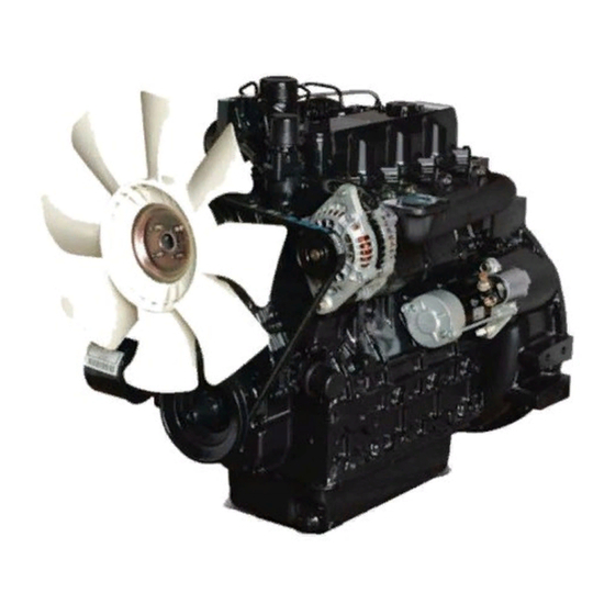
1.1 APPEARANCE
1.2 SPECIFICATIONS
1.3 PERFORMANCE CURVE
1.4 DIMENSIONS
1.5 GENERAL WARNING
CHAPTER 2. STRUCTURE AND FUNCTION
2.1 BODY
A. CYLINDER HEAD
B. CYLINDER BLOCK
C. CRANKSHAFT
D. PISTON AND PISTON RINGS
E. CONNECTING ROD
F. CAMSHAFT
G. FUEL CAMSHAFT
H. ROCKER ARM ASSEMBLY
I. INLET AND EXHAUST VALVES
J. TIMING GEARS
K. FLYWHEEL
2.2 LUBRICATING SYSTEM
A. FLOW OF LUBRICATING OIL
B. OIL PUMP
C. OIL FILTER AND RELIEF VALVE
D. OIL PRESSURE SWITCH
2.3 COOLING SYSTEM
A. FLOW OF COOLING WATER
B. WATER PUMP
C. THERMOSTAT
D. RADIATOR
E. RADIATOR CAP
2.4 FUEL SYSTEM
A. FLOW OF FUEL
B. FUEL FILTER
C. FUEL FEED PUMP
D. FUEL INJECTION PUMP
E. FUEL INJECTION NOZZLE
F. GOVERNOR AND IDLE COMPENSATING
PART 2 ENGINE
Advertisement
Table of Contents

Related Manuals for Daedong 3A165D


Summary of Contents for Daedong 3A165D
- Page 1 PART 2 ENGINE CHAPTER 1. GENERAL 1.1 APPEARANCE 1.2 SPECIFICATIONS 1.3 PERFORMANCE CURVE 1.4 DIMENSIONS 1.5 GENERAL WARNING CHAPTER 2. STRUCTURE AND FUNCTION 2.1 BODY A. CYLINDER HEAD B. CYLINDER BLOCK C. CRANKSHAFT D. PISTON AND PISTON RINGS E. CONNECTING ROD F.
- Page 2 2.5 INLET AND EXHAUST SYSTEM A. FLOW OF INLET AIR AND EXHAUST GAS B. AIR CLEANER C. MUFFLER 2.6 ELECTRICAL SYSTEM A. STARTER B. CHARGING SYSTEM CHAPTER 3. DISASSEMBLING AND SERVICING 3.1 TROUBLESHOOTING 3.2 SERVICING SPECIFICATIONS A. ENGINE BODY B. LUBRICATING SYSTEM C.
- Page 3 ENGINE FOREWORD This Workshop Manual has been prepared to provide servicing personnel with information on the mechanism, service and maintenance of DAEDONG Diesel engine A series. It consists of three parts, “GENERAL”, “STRUCTURE AND FUNCTION”, “DISASSEMBLING AND SERVICING” as following.
- Page 4 3 A 1 6 5 D 4 A 2 0 0 B The DAEDONG A series engines are vertical, water-cooled, 4-cycle, three or four cylinders diesel engines, they concentrate DAEDONG’s foremost technologies. With vortex combustion chamber, Bosch K type fuel injection pump, well-balanced designs, they feature greater power, low fuel...
-
Page 5: Specifications
ENGINE 1.2 SPECIFICAT I O N S M O D E L 3 A 1 6 5 D 4 A 2 0 0 B T y p e Vertical, water-cooled, 4-cycle diesel engine Vertical, water-cooled, 4-cycle diesel engine Number of cylinder 8 7 * 9 2 . -
Page 6: Performance Curve
ENGINE 1.3. PERFORMANCE CURV E... - Page 7 ENGINE 1.4 DIMENSION SAMPLE\TDSPEC. 3A165D(mm) 602.3 722.3 280.0 400.0 488.1 25.16 729.9 259.7 240.0 315.0 95.0 (in.) 23.71 28.44 11.02 15.75 19.22 9.91 28.74 10.00 9.45 12.40 3.74 4A200B(mm) 697.3 817.3 280.0 400.0 488.1 251.6 735.8 259.7 240.0 321.0 92.0 (in.)
-
Page 8: General Warning
• Replace gaskets or O-rings with new ones when reassembling, and apply grease on a O-ring and the oil seal when reassembling. • When exchanging parts, use DAEDONG genuine parts to maintain engine performance and safety. • To prevent oil and water leakage, apply non-drying adhesive to the gaskets according to this manual before reassembling. -
Page 9: Structure And Function
The Daedong vortex type combustion chamber is designed for high combustion efficiency and reducing fuel consumption. The glow plug assures... -
Page 10: Piston And Piston Rings
ENGINE C. CRANKSHAFT The crankshaft is made of forged steel and the journals, the crankpins and the bearing surface for the oil seal are induction-hardened to increase wear resistance. Each crankshaft journal is supported by the main bearing case (3) having a bearing inside. The front bearing-crankshaft bearing (1) is a solid type bushing and rear and intermediate bearings are a split type. -
Page 11: Fuel Camshaft
ENGINE F. CAMSHAFT The camshaft (3) is made of forged steel and its journal and cams are hardened to increase wear resistance. The cams on the camshaft open and close the inlet and exhaust valves with the push rods and rocker arms. The journals and their bearings are force-lubricated. -
Page 12: Inlet And Exhaust Valves
ENGINE I. INLET AND EXHAUST VALVES The valve and its guide of the inlet are different from those for the exhaust. Other parts, such as the spring , spring retainers , valve spring collets , valve stem seals are the same for both the inlet and the exhaust. -
Page 13: Lubricating System
ENGINE 2.2 LUBRICATING SYSTEM A. FLOW OF LUBRICATING OIL (1) Piston (2) Idle Gear (3) Oil Pump (4) Relief Va l v e (5) Strainer (6) Oil Filter Element (7) Bypass Va l v e (8) Oil Pan (9) Rocker Arm Shaft (10) Rocker Arm ( 11) Push Rod (12) Ta p p e t... -
Page 14: Oil Pressure Switch
ENGINE C. OIL FILTER AND RELIEF VA LV E The lubricating oil force-fed by the pump is filtered by the filter cartridge, passing through the filter element from the outside to the inside. When the filter element accumulates dirt and the pressure d i fference between the inside and the outside rises more than 98 kPa(1.0kgf/c m 2 , 14psi), the bypass valve (1) opens to allow the oil to flow from the inlet... -
Page 15: Cooling System
ENGINE 2.3 COOLING SYSTEM A. FLOW OF COOLING WAT E R (1) Water Return Pipe (2) Thermostat (3) Cylinder Head Water Jacket (4) Cylinder Block Water Jacket (5) Radiator (6) Cooling Fan (7) Water Pump The cooling system consists of a radiator (5), a centrifual water pump (7), a fan (6) and a thermostat (2). The water is cooled as it flows through the radiator core, and the fan behind the radiator pulls the cooling air through the radiator core. -
Page 16: Radiator Cap
ENGINE C. THERMOSTAT The thermostat is wax pellet type, which controls the flow of the cooling water to the radiator to keep the proper temperature. The case has a seat (1) and the pellet has a valve (2). The spindle attached to the case is inserted into the synthetic rubber in the pellet. -
Page 17: Fuel System
ENGINE 2.4 FUEL SYSTEM A. FLOW OF FUEL (1) Fuel T a n k (5) Injection Nozzle (2) Fuel Filter (6) Fuel Overflow Pipe (3) Injection Pump (7) Fuel Transfer Pump (4) Injection Pipe The fuel is fed from the fuel tank(1) through the fuel filter(2) to the injection pump(3) by the fuel transfer pump(7). -
Page 18: Fuel Feed Pump
ENGINE C. FUEL FEED PUMP The filtered fuel is fed to the injection pump by the fuel transfer pump. The diaphragm(6) is linked to the tappet(3) with the push rod(2). The tappet is reciprocated by the eccentric cam on the fuel c a m s h a f t ( 7 ) . - Page 19 ENGINE b. Operation of Pump Element (A) Before delivery As the tapper lowers, the plunger(2) lowers and fuel is drawn into the delivery chamber(1) through the feed hole(4) from the fuel chamber(5). (B) Beginning of delivery When the plunger is pushed up by the cam and the head of the plunger closes the feed hole, the pressure in the delivery chamber rises to push the relief plunger(2) open.
- Page 20 6. Relief Plunger E. FUEL INJCECTION NOZZLE The nozzle is a throttle-type one. It features low fuel consumption and works well with DAEDONG combustion chamber. The nozzle valve opening pressure is about 13.7 to 14.7 MPa(140 to c m 2...
- Page 21 ENGINE F. GOVERNOR AND IDLE COMPENSAT I N G a. Disassembled Vi e w (1) Start Spring (2) Governor Sping 1 (3) Governor Sping 2 (4) Fork Lever 1 (5) Fork Lever 2 (6) Fork Lever Shaft (7) Fork Lever Holder (8) Governor lever (9) Fuel Camshaft (10) Governor Ball Case...
- Page 22 ENGINE b) At Idling At the idling position of the speed control lever(15), the governor spring 1 (2) is free and the governor spring 2 (3) does only act slightly. The governor sleeve (12) is pushed leftward by a centrifugal force of steel ball(13).
-
Page 23: Inlet And Exhaust System
ENGINE 2.5 INLET AND EXHAUST SYSTEM A. FLOW OF INLET AIR AND EXHAUST GAS (a) Inlet Air (b) Exhaust Gas (1) Inlet Manifold (2) Air Cleaner (3) Cylinder Head (4) Muff l e r (5) Exhaust Manifold B. AIR CLEANER The air cleaner is dry-cyclone type and easy to maintain. -
Page 24: Electrical System
ENGINE 2.6 ELECTRICAL SYSTEM A. STA R T E R The magnet-switch type starter is composed of two main section. The first section converts electrical energy into mechanical rotaion to turn the engine crankshaft. It is composed of the field coil, armature, brush, commutator, pinion, overrunning clutch etc. -
Page 25: Disassembling And Servicing
ENGINE 3. DISASSEMBLING AND SERVICING 3.1 TROUBLESHOOTING Symptom Probable Cause Solution • Not fuel Replenish fuel • Air in the fuel system Vent air • Water in the fuel system Change fuel and repair or flush fuel system • Fuel pipe clogged Clean •... - Page 26 ENGINE S y m p t o m Probable Cause S o l u t i o n • Excessive engine oil Reduce to the specified level Either White or • Piston ring and bore worn or stuck Repair or replace Blue Exhaust •...
- Page 27 ENGINE S y m p t o m Probable Cause S o l u t i o n High Oil• Improper type of oil Use the specified type of oil P r e s s u r e • Relief valve defective R e p l a c e •...
-
Page 28: Servicing Specifications
0.140rad 8 before T.D.C Close 0.611rad 45 after B.D.C Exhaust Valve Open 0.785rad 45 before B.D.C Close 0.140rad 8 after T.D.C d. Cylinder Bore ø 87.000~87.022mm 3A165D Cylinder Bore Inner ø 3.4252~3.4261in. 0.15mm Diameter ø 83.000~83.002mm 0.0059in 4A220B ø 3.2677~3.2686in. - Page 29 24.000 to 24.021mm Tappet Guide I.D 0.94488 to 0.94571in. h. Camshaft Item Factory Specification Allowable Limit 0.01mm 0.05mm Camshaft Alignment 0.0031in. 0.0020in. IN.(3A165D, 4A200B) 33.59mm 33.54mm 1.3224in. 1.3205in. Cam Height 33.69mm 33.64mm 1.3264in. 1.3244in. Clearance Between Camshaft 0.050 to 0.091mm 0.15mm...
- Page 30 ENGINE j. Piston-Piston Ring Item Factory Specification Allowable Limit 25.000 to 25.006mm 25.03mm Piston Pin-bore I.D 0.98425 to 0.98448in. 0.9854in. Clearance between 2nd ring and ring groove 0.020 to 0.060mm 0.15mm 0.00079 to 0.00236in. 1.0059in. 2nd ring groove width 3.010 to 3.030mm 0.11850 to 0.11929in.
-
Page 31: Cooling System
7~9mm [deflection at 98 N(10kgf, 22lbs) of force] 0.28 to 0.35in D. FUEL SYSTEM a. Inject Pump Injection Timing(BTDC) 3A165D, 4A200B b. Injection Nozzle 13.73 to 14.715MPa 140 to 150kgf/cm 2 Fuel Injection Pressure 1991 to 2133psi No fuel leak for 5 sec. -
Page 32: Tightening Torques
ENGINE E. TIGHTENING TORQUES Item Size*Pitch kgf•m N•m ft-lbs Cylinder head screws M11*1.25 10.5~11.0 103.0 to 107.9 75.9 to 79.6 Head cover nuts M10*1.25 0.7~0.9 6.9 to 8.8 5.1 to 6.5 * Bearing case screw 1 M9*1.25 4.7~5.2 46.1 to 51.0 34.0 to 37.6 * Bearing case screw 2 M10*1.25... -
Page 33: Checking, Disassembling And Servicing
ENGINE 3.3 CHECKING, DISASSEMBLING AND SERV I C I N G A. ENGINE DISASSEMBLED VIEW (1) Injection Pipe (13) Cylinder Block (25) Governor Fork Lever (37) Bearing case Screw 1 (2) Injection Nozzle (14) Va l v e (26) Injection Pump Gear (38) Starter (3) Glow Plug (15) Piston (27) Idle Gear... -
Page 34: External Components
ENGINE B. EXTERNAL COMPONENTS a. Checking and Adjusting 1) Fan Belt Measure the deflection, depressing the belt halfway between the fan drive pulley and the alternator pulley at 98n(10kgf, sslbs) of force. If the deflection is not between the factory specifications, loosen the bolts and nuts, and relocate the alternator to adjust. - Page 35 ENGINE 2) Solenoid 1. Disconnect the stop lever 1(5) from the engine stop lever (2). 2. Remove the screw (3) ,(4) and (6) . 3. Remove the solenoid(8) with its support. (When reassembling) • Loosen the solenoid mouting screws. • Install the support and complete the linkage between the solenoid and the engine stop lever.
-
Page 36: Engine Body
ENGINE C. ENGINE BODY a. Checking and Adjusting 1) Compression Pressure 1. Run the engine until warmed up. 2. Stop the engine and remove the air cleaner, the m u ffler and all nozzle holders. 3. Set a compression tester to the adapter installed in the nozzle holder hole and fixed with the locating s c r e w. - Page 37 ENGINE 2) Valve Clearance 1. Remove the cylinder head cover and the timing window cover on the flywheel housing and all glow p l u g s . 2. Turn the flywheel and align the 1 TC or 1.4 TC mark with the timing mark of window on the flywheel housing to position the 1st cylinder valves at the top dead center during compression.
- Page 38 ENGINE b. Disassembling and Assembling (A) Cylinder Head Cover, Glow Plugs and Fuel Overflow pipes. 1. Remove the injection pipes and over flow pipe. 2. Remove the glow plugs. 3 . Remove the injection nozzles and gaskets, heat seals. 4. Remove the cylinder head cover. (When reassembling) •...
- Page 39 ENGINE I M P O RTANT : • When assembling the rocker arm assembly, locate groove of rocker arm shaft on stud bolt. (1) Rocker Arm Shaft (3) Rocker Arm Bracket (2) Rocker Arm (4) Screw • 4.9 to 5.7 kgf Tightening •...
- Page 40 ENGINE (E) Va l v e 1. Compress the valve spring with a valve spring replacer and remove the collect (2). 2. Remove the valve spring retainer (3), valve spring (4), valve stem seal (5) and the valve (1). I M P O RTANT : •...
- Page 41 ENGINE (C) Speed Control Plate and Start Spring 1. Remove the speed control plate and the governor spring on it. (When reassembling) •Be careful not to drop the governor springs 1,2 into the gear case. •Apply a liquid gasket both side of speed control plate gasket.
- Page 42 ENGINE (F) Gear Case 1. Remove the gear case. (When reassembling) •Stick the O-ring (1) to the gear case with thin grease to prevent from coming off during r e a s s e m b l i n g . •Apply grease to the crankshaft oil seal lip on the gear case and take care not to be rolled when i n s t a l l i n g .
- Page 43 ENGINE I M P O RTANT : • Install the idle gear, aligning the alignment marks referring to the figure. (1) Idle Gear (2) Crank Gear (3) Crank Gear Collar (4) Oil Slinger (5) O-ring (6) Crankshaft Collar (7) Oil Pump Gear (8) Injection Pump Gear (9) Cam Gear (I) Camshaft...
- Page 44 ENGINE 3) Connection Rod and Piston (A) Oil Pan and oil filter 1. Remove the engine stand and the oil pan. 2. Remove the strainer (1). (When reassembling) • Be sure to install the O-ring (2) between the strainer and the cylinder block. (1) Strainer (2) O-ring (I) Piston and Connecting Rod...
- Page 45 ENGINE (C) Piston Ring and Piston Pin 1. Remove the piston rings with a piston ring replacing tool. 2. Remove the piston pin. (When reassembling) • Clean all the parts before assembling. • Heat the piston in approx. 80 ( 1 7 6 )of oil for 10 to 15 minutes, when inserting the piston pin into the piston.
- Page 46 ENGINE 4) Crankshaft (A) Flywheel 1. Install the stopper to the flywheel and loosen the s c r e w. 2. Remove the flywheel stopper and the flywheel. (When reassembling) • Clean the end of crankshaft and the mating surface of the flywheel.
- Page 47 ENGINE (D) Main Bearing Case 1. Remove the main bearing case screws 1 and remove the main bearing case (4). 2. Remove the thrust bearing from the flywheel end bearing case. (1) Main Bearing Case 1, 2, 3 (2) Thrust Bearings (3) Main Bearing Case Assembly (4) Main Bearing Case Screw 1 (5) Crankshaft Bearing 2...
- Page 48 ENGINE c. Servicing 1) Cylinder Head and Va l v e (A) Cylinder Head Surface Flatness 1. Throughly clean the cylinder head surface. 2. Place a straight edge on the cylinder head and measure the clearance with a feeler gage as shown in the figure.
- Page 49 ENGINE (D) Valve recessing 1. Clean the cylinder head, the valve face and the s e a t . 2. Insert the valve in the guide. 3. Measure the valve recessing with a depth gauge. 4. If the recessing exceeds the allowable limit, replace the valve and check the valve seating.
- Page 50 ENGINE (G) Valve Spring Squareness (Ti l t ) 1. Place the spring on the surface plate and a squre at its side. 2. Measure the maximum distance A(See figure), rotating spring. 3. If the measurement exceeds the allowable limit r e p l a c e .
- Page 51 ENGINE (B) Idle Gear Side Clearance 1. Pull the idle gear collar 2 (1) and push the idle gear (2) to each end. 2. Measure the clearance A between the idle gear and the idle gear collar 2 with a feeler guage. 3.
- Page 52 ENGINE ( E ) Idle Gear Oil clearance 1. Measure the idle gear shaft O.D. with an outside m i c r o m e t e r. 2. Measure the idle gear bushings I.D. with an inside m i c r o m e t e r. 3.
- Page 53 ENGINE (H) Camshaft Alignment 1. Support the camshaft with V blocks on the surface plate at both end journals and set a dial indicator with its tip on the intermediate journal. 2. Rotate the camshaft in the V block and get the eccentricity(half of the measurement).
- Page 54 ENGINE (B) Piston Pin and Brushing Clearance 1. Measure the piston pin O.D. with an outside m i c r o m e t e r. 2. Measure the piston pin busing I.D. with an inside m i c r o m e t e r. 3.
- Page 55 ENGINE ( E ) Piston Ring Clearance 1. Clean the ring and the ring grooves, and install each ring its groove. 2. Measure the clearance between the ring and the groove with a feeler gauge. 3. If the clearance exceeds the allowable limit, replace the piston ring.
- Page 56 ENGINE 4) Crankshaft ( A ) Flywheel Deflection and Crankshaft End Play 1. Set a dial indicator with its tip on the rear friction face of the flywheel near the edge. 2. Turn the flywheel and measure the deflection or the uneven wear.
- Page 57 ENGINE ( C ) Crankshaft Journal and Bearing 1 Oil Clearance 1. Measure the I.D. of the crankshaft bearing 1 with an inside micrometer. 2. Measure the O.D. of the crankshaft journal with an outside micrometer. 3. If the clearance exceeds the allowable limit, replace the bearing referring to Replacing Crankshaft Bearing 1.
- Page 58 5) Cylinder bore ( A ) Cylinder bore diameter 1. Measure the cylinder liner I.D.at sit positions shown in the figure to find the maximum wear. ø 83mm 0~+0.022mm 4A200B ø 3.2677in. 0~+0.00087in. ø 87mm 0~+0.022mm 3A165D ø 3.4252in. 0~+0.00087in.
- Page 59 ENGINE D. LUBRICATING SYSTEM a. Checking (A) Engine Oil Pressure 1. Remove the oil pressure switch and install adaptors and pressure tester. 2. Start the engine and run it until it is warmed up, and measure the oil pressure both at idling and rated speed.
- Page 60 ENGINE b. Servicing (A) Rotor and Lobe Clearance of oil pump 1. Measure the clearance between the outer and inner rotor with a feeler gauge. 2. Measure the clearance between the outer and the housing with a feeler gauge. 3. If the clearance exceeds the allowable limit, replace the pump Outer Factory...
- Page 61 ENGINE a. Checking Adjusting (A) fan Belt 1. Measure the deflection, depressing the belt halfway between the fan drive pulley and the alternator pulley at 98N(10kgf, 22lbs) of force. 2. If the deflection is not between the factory specifications, loosen the bolts and nuts, and relocate the alternator to adjust.
- Page 62 ENGINE b. Disassembling and Assembling (A) Thermostat 1. Remove the thermostat cover (2). 2. Take out the thermostat (1). (When reassembling) • Apply liquid gasket(Three Bond 1215 or equivalent) to the gasket. (1) Thermostat (2) Thermosat cover ( B ) Water Pump 1.
- Page 63 ENGINE F. FUEL SYSTEM a. Checking and Adjusting 1) Injection Pump ( A ) Injection Term ( Injection Timing ) 1. Remove the injection pipes. 2. Set the speed control lever to the maximum fuel discharge position. 3. Turn the flywheel counterclockwise (facing the flywheel) until the fuel flow through to the hole of the delivery valve holder (1).
- Page 64 ENGINE Fuel 23.44Mpa Factory 150kgf/cm 2 injection spec. pressure 3400psi 91Mpa Pressure Allowable 10kgf/cm 2 drop limit 142psi b. Injection Nozzle CAUTION : • Never contact with spraying diesel fuel under pressure, which can have sufficient force to penetrate the skin, causing serious personal injury. •...
- Page 65 ENGINE b. Disassembling and Assembling 1) Injection pump I M P O RTANT : • If replacing the pump element, the amount of fuel injection should be adjusted on specified bench. (1) Pump body (2) Control rack (3) Delivery valve holder (4) Delivery valve spring (5) Delivery valve (6) Tappet roller...
- Page 66 ENGINE G. ELECTRICAL SYSTEM 1) Starter ( A ) Motor test 1. Disconnect the connecting lead from the “C” terminal of the starter and connect a jumper lead from the connecting lead to the positive battery t e r m i n a l . 2.
- Page 67 ENGINE 3) Alternator (A) Measurement of adjust voltage Disconnect the terminal B+ of alternator and connect ohm - meter with terminal serially. Then connect load-resistance between ohm - meter and ground s e r i a l l y. Adjust voltage can be measured between B+ terminal and ground.
- Page 68 ENGINE ( D ) Insulation test of rotor and stator Test insulation of rotor and stator up to 40V maximum. If there is no problem for insulation, lamp will be off . (E) Continuity test of coil Test it with DC test lamp or ohm-meter. If the coil is not connected the test lamp is off and resistance of the ohm-meter will be infinite(œ).
Need help?
Do you have a question about the 3A165D and is the answer not in the manual?
Questions and answers