Table of Contents
Advertisement
Quick Links
Advertisement
Table of Contents

Summary of Contents for Lika Modbus LDT10
-
Page 1: User's Guide
User's guide LDT10 RS-485 version Smart encoders & actuators... - Page 2 Tous droits réservés. This document and information contained herein are the property of Lika Electronic s.r.l. and shall not be reproduced in whole or in part without prior written approval of Lika Electronic s.r.l. Translation, reproduction and total or partial modification (photostat copies, film and microfilm included and any other means) are forbidden without written authorisation of Lika Electronic s.r.l.
-
Page 3: Table Of Contents
General contents User's guide.......................................1 General contents....................................3 Typographic and iconographic conventions..........................4 Preliminary information..................................5 1 Safety summary..................................6 1.1 Safety.....................................6 1.2 Electrical safety.................................6 1.3 Mechanical safety..............................7 1.4 Precautions and usage tips..........................7 2 Identification....................................8 3 Mechanical installation................................9 3.1 Overall dimensions (Figure 1)..........................9 3.2 Mounting the panel (Figure 2)...........................9 3.3 Cleaning the screen...............................11 4 Electrical connections................................12 4.1 Connectors (Figure 3)............................13... -
Page 4: Typographic And Iconographic Conventions
Typographic and iconographic conventions In this guide, to make it easier to understand and read the text the following typographic and iconographic conventions are used: parameters and objects both of the device and the interface are coloured in GREEN; • alarms are coloured in RED;... -
Page 5: Preliminary Information
Refer to the manuals describing the MODBUS interface models (MAN RDx MB). Please download the complete technical documentation of the RD rotary actuators at www.lika.biz > ROTARY ACTUATORS > ROTARY ACTUATORS / POSITIONING UNITS (DRIVECOD). For detailed technical specifications please consult the product datasheet. -
Page 6: Safety Summary
• elsewhere in this manual violates safety standards of design, manufacture, and intended use of the equipment; Lika Electronic assumes no liability for the customer's failure to comply • with these requirements. 1.2 Electrical safety Turn off the power supply before connecting the device;... -
Page 7: Mechanical Safety
LDT10 - to guarantee a correct working of the device, avoid using strong magnets on or near by the unit; - minimize noise by connecting the device to ground. Make sure that ground is not affected by noise. Use the pin 3 available in the 3-pin connector 1 (refer to the “Electrical connections”... -
Page 8: Identification
The information is listed in the delivery document too. Please always quote the order code and the serial number when reaching Lika Electronic for purchasing spare parts or needing assistance. For any information on the technical characteristics of the product refer to the technical catalogue. -
Page 9: Mechanical Installation
LDT10 Mechanical installation WARNING Installation and maintenance operations have to be carried out by qualified personnel only, with power supply disconnected and mechanical parts compulsorily in stop. 3.1 Overall dimensions (Figure 1) Figure 1 - LDT10 lay-out 204.4 mm 151 mm 26.5 mm 137 mm 191.5 mm... - Page 10 LDT10 Ensure that enough free space is left at the rear to allow the air circulation. Ensure that 200 mm / 7.87” of free space is left all around. When you mount the panel make sure that the air openings are not obstructed. To fix the touch panel cut a rectangular hole in the installation support.
-
Page 11: Cleaning The Screen
LDT10 3.3 Cleaning the screen WARNING Switch the power supply off before cleaning the front screen. Always use a soft and clean cloth such as a microfibre or cotton cloth to remove the dust from the display. Gently wipe the surface without exerting any pressure. -
Page 12: Electrical Connections
LDT10 Electrical connections WARNING Power supply must be turned off before performing any electrical connection! Figure 3: Electrical connections 3-pin connector – Power supply USB service port – Firmware upgrade (see on page 39) DSub 9-pin female RS-485 COM1 port – MODBUS interface Reserved USB port –... -
Page 13: Connectors (Figure 3)
LDT10 4.1 Connectors (Figure 3) LDT10 Power supply 3-pin connector Pin Function +24Vdc power supply 0 Vdc power supply RS-485 COM1 serial port – MODBUS interface Dsub 9-pin female Pin Function MODBUS A (RS-485) MODBUS B (RS-485) 2 … 5 Not connected 7 …... - Page 14 LDT10 Power supply M16 3-pin male connector Pin Function A coding +24Vdc 10% motor +24Vdc 10% controller 0 Vdc motor and controller RS-485 MODBUS interface M12 5-pin connector A coding Pin Function BUS IN male BUS OUT female 1 - 2 Not connected GND (RS-485) MODBUS A (RS-485) MODBUS B (RS-485)
-
Page 15: Ground Connection
LDT10 Power supply Pin Function M18 4-pin male connector +24Vdc 10% motor +24Vdc 10% controller 0 Vdc motor 0 Vdc controller RS-485 MODBUS interface M12 5-pin connector A coding Pin Function BUS IN male BUS OUT female 1 - 2 Not connected GND (RS-485) MODBUS A (RS-485) High, + MODBUS B (RS-485), Low, -... -
Page 16: Node Address: Node Id
LDT10 HMI interface is a MODBUS Master device, the networked actuators are Slave nodes, so they must be provided with an univocal address. Lika devices support the UNICAST mode, so the Master node issues a MODBUS request to an individual Slave. -
Page 17: Data Transmission Rate: Baud Rate And Parity Bit
LDT10 WARNING In the Network setup page if you match a node with a wrong position (for instance you match the Actuator 2 position with an actuator having an address different from “2”), then the communication cannot be established and the COMMUNICATION ERROR following message will appear on the display. -
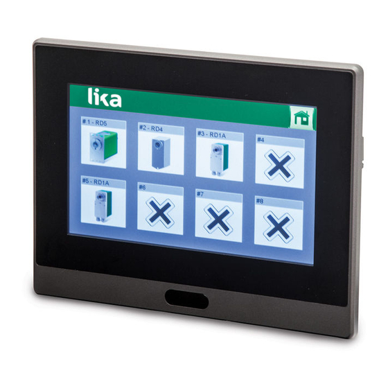
Page 18: Hmi Interface
LDT10 HMI interface 5.1 Preliminary information Except for the first time the panel is started (for this case please refer to the “ 5.2 Starting the interface for the first time” section here below), at power-on the Home page appears on the display. From the Home page you can enter the full set of pages of the interface, provided that you comply with the protection level L required by the page. -
Page 19: Starting The Interface For The First Time
LDT10 5.2 Starting the interface for the first time When you start the interface for the first time, the system displays the Network setup page. In normal work condition this page can be accessed only by Level 2 – Administrator users while Level 0 - User and Level 1 – manager users (see the ”5.3 Safety levels”... - Page 20 LDT10 The access to the functions of the basic level 0 is free and does not require any password. While the access to the functions of the level 1 and the level 2 requires a password to be entered. Passwords cannot be modified. To enter a password, you must first access the Network page (see on page 25) and then press the key in the menu at the top of the page.
-
Page 21: Level 0 - User
LDT10 5.3.1. Level 0 - User It is the first security level and allows for a basic use of the interface. It does not require a password and is mainly aimed at the users that are involved in the production process. In this level the user is allowed to display most of the pages and to launch the recipes in order to start a production. -
Page 22: Level 2 - Administrator
LDT10 WARNING When you start the interface for the first time, as it is compulsorily necessary to match one actuator at least with the interface, the system allows also the Level 0 and Level 1 users to enter the Network setup page and match the available devices with the node positions. -
Page 23: Network Setup Page
LDT10 5.4 Network setup page WARNING Level 2 – Administrator users only are allowed to manage the functions available in this page. As previously stated, when you start the interface for the first time, the system displays the Network setup page. In normal work condition this page can be accessed only by Level 2 –... - Page 24 LDT10 necessary to specify the actuator model that you are going to match with the node position. For instance, if you need to install a RD1A-...-MB- actuator having “1” physical address then you must press the RD1 key in the Actuator 1 line and optionally enter a brief description (max.
-
Page 25: Network Page
LDT10 5.5 Network page key to enter the Network page. Press the WARNING All users are allowed to display this page yet some functions are available to the higher safety level users only (password protected levels). The Network page is some sort of key point in the structure of the interface pages. -
Page 26: Node Control Page
LDT10 key in the menu at the top of the page to enter the Network Press the setup page. For complete information please refer to the “5.4 Network setup page” section on page 23. Press the key in the menu at the top of the page to move back to the Home page. - Page 27 LDT10 WARNING All users are allowed to display this page yet some functions are available to the higher safety level users only (password protected levels). This page can be divided into three sections: on the left side section of the screen the parameters that are used to set •...
- Page 28 LDT10 Target position field allows to set the target position, i.e. the position that the actuator is commanded to reach. The value is expressed in pulses. See the “Target position” register in the “User's guide” of the specific actuator. After having set the target position you can start and check the motion of the axle to the target position by pressing the following keys: JOG -, JOG +,...
-
Page 29: Node Status Page
LDT10 5.7 Node status page WARNING All users are allowed to display this page. When you press the DETAILS key in the Node control page you enter the Node status page. In this page the complete list of the available alarms and statuses is displayed. -
Page 30: Node Setup Page
LDT10 5.8 Node setup page WARNING All users are allowed to display this page yet the functions are available to the Level 2 – Administrator users only. SETUP key in the Node control page you enter the When you press the Node setup page. -
Page 31: Decimals
LDT10 As soon as you confirm the entry, if the entered value and any other setting are inconsistent, a red box appears on the left side of the fields. All the parameters in this page are described in the “User's guide” of the specific actuator, for a comprehensive description please refer to it. -
Page 32: Backlash Direction
LDT10 EXAMPLE Let's suppose that the actuator is installed on a 5-mm pitch worm screw. If you Pulse per revolution Decimals = 500 and = 2, at each rotation of the screw the system performs a 5-mm pitch with a resolution of one hundredth of a millimetre. - Page 33 LDT10 Backlash, sometimes called lash or play, is clearance or lost motion in a mechanism caused by gaps between the parts. It can be defined as "the maximum distance or angle through which any part of a mechanical system may be moved in one direction without applying appreciable force or motion to the next part in mechanical sequence", and is a mechanical form of deadband.
-
Page 34: Backlash Step Length
Press the DEFAULT key below right in the page to restore the default values of the actuator. Default parameters are set at the factory by Lika Electronic engineers to allow the operator to run the device for standard operation in a safe mode. -
Page 35: Advanced Node Setup Page
LDT10 key at the top of the page to enter the Network page. For any Press the information please refer to the “5.5 Network page” section on page 25. key at the top of the page to move back to the Home page. For Press the any information please refer to the “5.10 Home page”... - Page 36 Press the DEFAULT key below right in the page to restore the default values of the actuator. Default parameters are set at the factory by Lika Electronic engineers to allow the operator to run the device for standard operation in a safe mode.
-
Page 37: Home Page
LDT10 5.10 Home page The Home page is displayed at power-on (see the only exception in the “5.2 Starting the interface for the first time” section on page 19) and allows to create and manage the recipes. It is mainly aimed at the users that are involved in the production process (Level 0 –... - Page 38 LDT10 If you need, for instance, to create the recipe 1, you must select the field by pressing the 1 key in the Select program column first; the key of the selected recipes will be highlighted in green; then you must enter a brief description (max.
-
Page 39: Firmware Upgrade
Lika Electronic to make new improved firmware programs available during the lifetime of the product. The firmware upgrading program consists of a single file having .PRP extension. It is released by Lika Electronic Technical Assistance & After Sale Service. MAN LDT10 E 1.2 HMI interface... - Page 40 To upgrade the firmware program please proceed as follows: 1. switch the power supply off; 2. copy the .PRP file provided by Lika Electronic onto a USB flash drive and then plug the USB flash drive into the USB service port 2 (Figure 3);...
- Page 41 7. once you press the UPDATE FROM FILE key the Open dialogue box appears on the screen: you must open the folder where the firmware upgrading .PRP file released by Lika Electronic is located; 8. select the .PRP file and confirm the choice by pressing the OPEN button, the dialogue box closes;...
- Page 42 LDT10 WARNING Do not switch the power supply off during installation! 10. as soon as the operation is carried out, if it has been completed successfully the Panel Setup page will be displayed; 11. turn the power supply off and then on again to start the panel in the normal display mode.
- Page 43 This page intentionally left blank...
- Page 44 Document release Release date Description Interface 09.09.2015 First issue 22.04.2016 New software version 07.11.2016 New software version, RD6 actuator implemented Lika Electronic Via S. Lorenzo, 25 • 36010 Carrè (VI) • Italy Tel. +39 0445 806600 Fax +39 0445 806699 info@lika.biz •...
Need help?
Do you have a question about the Modbus LDT10 and is the answer not in the manual?
Questions and answers