
Summary of Contents for Termal HOKKAIDO HWMI 300 A
- Page 1 WATER HEATER INSTALLATION & USER'S MANUAL Model HWMI 300 A WARNING! PLEASE READ CAREFULLY THIS MANUAL BEFORE INSTALLING THE WATER HEATER - 1 -...
- Page 2 TERMAL S.R.L. Via della Salute, 14 -- 40132 -- Bologna -- ITALY EUROPEAN REGULATIONS CONFORMITY FOR THE MODELS: Water Heater: HWMI 300 A DISPOSAL REQUIREMENTS: All the products are in conformity with the following European provision: Your Water Heater is marked with this symbol.
- Page 3 WARNING This Unit is required reliable earthing before usage, otherwise might cause death or injury. Please ask Authorized Technical Service for reliable earthing connection. Your safety is the most important thing we concerned! - 3 -...
-
Page 4: Table Of Contents
Table of Contents PRODUCT'S OUTLINE ......................5 PRECAUTIONS & ACCESSORIES ..................6 INSTALLATION ........................8 WIRING ..........................13 OPERATING INSTRUCTIONS ....................15 TRIAL RUNNING & CAPABILITY ................... 22 MAINTENANCE ........................24 DIAGNOSTIC & ERROR CODES ..................25 AUTOMATIC RESTART AFTER A BLACKOUT ..............27 - 4 -... -
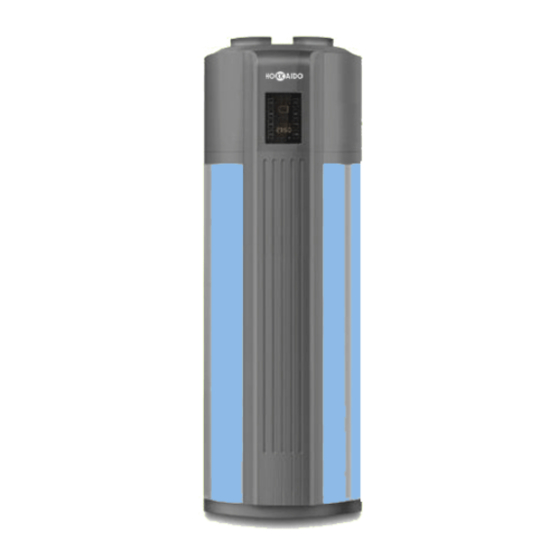
Page 5: Product's Outline
PRODUCT'S OUTLINE PARTS NAMES Air Outlet Air Inlet Top Cover Filter Evaporator Electronic Control Fan Assy Junction Box Cover Compressor Front Cover Display Back Cover Junction Box Cover PT Valve Anode Rod Water Outlet Front Decorative Electric Heater Board Cover, Electric Solar Sensor Heater Solar Water Outlet... -
Page 6: Precautions & Accessories
PRECAUTIONS & ACCESSORIES WARNING • Ask the Authorized Technical Service for installation of Water Heater Unit. Improper installation may result in water leakage, PRECAUTIONS electric shock or fire. • Ask the Authorized Technical Service for the repair To prevent injury to the User or other people and and maintenanance. - Page 7 PRECAUTIONS & ACCESSORIES ACCESSORIES CAUTION Table 2-1 • The earth pole of terminal must be earthed, and the Accessory name Q.ty Sharp Purpose rated current must be more than 10A. Make sure that power supply terminal and power supply plug User &...
-
Page 8: Installation
INSTALLATION • Precautions before installation INSTALLATION LOCATION • Decide the correct way of conveying the equipment. • Enough space must be kept for easy installation and maintenance. • If the Unit has to be installed in a metal part of the •... - Page 9 INSTALLATION INSTALLATION WARNING • Water Heater Units must be installed only by Authorized Technical Service. The User must never try to install the appliance by himself. Incorrect installation may result in water leakages, electric shock or fire. • The equiment must be installed far from direct sunlight and from other heat appliances.
- Page 10 INSTALLATION PIPELINE CONNECTION NOTE • A safety valve should be installed at the water • Pipeline Connection Drawing inlet of the Unit. • Arrange water pipes and connected fittings as it is shown in Fig. 5-1. In case of installation in a place where outside temperature is below freezing point, insulation must be provided for all hydraulic components.
- Page 11 INSTALLATION • • Duct Connection Way Note: Upon connection of canvas, airflow rate and capacity in heat pump system decrease. • • Air inlet and outlet do not need to connect with canvas. Air inlet without canvas, air outlet connect to canvas: A≤10m.
- Page 12 INSTALLATION • Canvas Duct Description Straight-line Straight-line length (m) Bent pressure drop (Pa) Bent’s qty. Canvas Duct Dimension(mm) pressure drop (Pa/m) Round canvas duct Ø190 ≤2 ≤10 ≤2 ≤5 Rectangle canvas duct 190x190 ≤2 ≤10 ≤2 ≤5 Other shaped Refer to above data canvas duct Note: In case of need, canvas duct to be connected at air outlet better than at inlet.
-
Page 13: Wiring
WIRING ELECTRIC CONNECTION WARNING CAUTION For safety, a Creepage Breaker must be installed on the Unit near the power supply. • Moreover, the Unit must be effectively earthed. The power supply for the Unit must correspond to the rated voltage. •... - Page 14 WIRING 6.2 Wiring Diagram 220-240V~ 50 Hz Main Control Board Compressor Electric Heater Pressure Switch Compressor Water Tank Tube Temp. Sensor Ambient temp. Sensor T5L: Tank Temp. Sensor (lower) T5U: Tank Temp. Sensor (upper) Discharge Temp. Sensor (upper) Return air temperature sensor Earthing Fig.
-
Page 15: Operating Instructions
OPERATING INSTRUCTIONS OPERATION INSTRUCTION 7.1 Operation steps Before using this Unit, please follow the steps below. Filling the Water Tank: if Unit is used for the first time or used again after emptying the tank, please make sure that the tank is full of water before turning on the power. Method: see Fig. - Page 16 OPERATING INSTRUCTIONS • Display TEMP-SET ALARM FILL WATER HIGH TEMP ECONOMY MODE LOCK HYBRID MODE OUTLET TEMP E-HEATER MODE TIMER TIME ON TIME OFF CONFLICT HIGH TEMP indicator: When the setting temp. exceeds 50°C, it lights up to remind you that the outlet temperature is too high.
- Page 17 OPERATING INSTRUCTIONS • Buttons CANCEL key, used to cancel UP key, used to MODE key, used Timer and lock all to set different add time or Unit’s keys ON/OFF key, used to temperature. operation modes. (LOCK function). turn the Unit on or off. ON\OFF CANCEL MODE...
- Page 18 OPERATING INSTRUCTIONS • LOCK/UNLOCK Press the UP and DOWN keys, In order to prevent wrong operation, a special lock you can adjust the hour. function has been designed. If there is no operation for 1 minute, the Unit will be locked automatically, and display shows the Lock indicator.
- Page 19 OPERATING INSTRUCTIONS Press the UP and DOWN key, you can increase Press the UP and DOWN key, or decrease the water temperature. you can adjust the hour.. Fig. 7-6 Press the TIME ON key again When the set temperature is higher than 50°C, and wait about 10 sec., flashing the HIGH TEMP indicator will light.
- Page 20 OPERATING INSTRUCTIONS Stop operation for about 10 sec., flashing Press the TIME ON key again, the minute stops and TIME ON + TIME OFF set is digits stop flashing and the hour digits start. finished. TIME Fig. 7-10 To cancel TIME ON/OFF set: In the unlocked state, press the CANCEL key for 1 second, the TIME Press the UP and DOWN keys, you can...
- Page 21 OPERATING INSTRUCTIONS Error Code which means a conflict ALARM indicator flashes to with operating conditions of heat indicate that there is a malfunction pump TEMP-SET ALARM Fig. 7-13 Press CANCEL key to stop • In case of continuous operation for 20 hours the buzzer.
-
Page 22: Trial Running & Capability
TRIAL RUNNING & CAPABILITY RUNNING AND CAPABILITY 8.1 Trial Running Before running, please check the following items first: • Correct installation of the system; • Correct connection of pipeline and wiring; • Leakage of the refrigerant pipeline tested; • Efficient drainpipe; •... - Page 23 TRIAL RUNNING & CAPABILITY • In the following circumstances, self-protection starts: NOTE 1) Air inlet or outlet is obstacled; In E-Heater mode, only half tank of water, i.e. 150L, 2) The evaporation is covered with too much dust; could be heated every time. 3) Incorrect power supply (exceeding the range of 207~253V).
-
Page 24: Maintenance
MAINTENANCE MAINTENANCE • Ordinary maintenance of Water Heater • Check the connection between power supply plug and socket, and ground wiring regularly. • In some cold sites (below 0°C), if the system will be stopped for a long time, all the water should be released for preventing the risk of freezing of inner tank and damages to e-heater. -
Page 25: Diagnostic & Error Codes
DIAGNOSTIC & ERROR CODES DIAGNOSTIC • Non-error Malfunction • 3-minutes Protection After a blackout, when power is supplied again, it is necessary to wait 3 minutes before Unit may restart (for protecting compressor). • In case of intervention of a self-protection, please check the following: - When the Power indicator lights up, if the system is forced to run while startup requirements have not been met;... - Page 26 DIAGNOSTIC & ERROR CODES • Table of Error Codes Table 10-2 Display Malfunction Description Error of sensor T5U Error of sensor T5L Tank and Wired Controller communication error Evap. pipe temperature sensor error Ambient temperature sensor error Discharge pipe temp. sensor error Heat Pump system error Electric leakage protection TH sensor condenser failure...
-
Page 27: Automatic Restart After A Blackout
AUTOMATIC RESTART AFTER A BLACKOUT • When a power failure occurs during operation, the Water heater stops immediately. • When power is restored, the Water Heater will automatically restart after 3 minutes have elapsed since power is restored. This means it is not required to press the "ON/ OFF"... - Page 28 HOKKAIDO Srl 14, Via della Salute 40132 Bologna - Italy Tel. +39.051.41.33.111 Fax +39.051.41.33.112 www.hokkaido.eu www.termalgroup.com Due to on-going technological development of the Products by the Manufacturer, we reserve the right to vary the technical specifications at any time and without notice.