
Related Manuals for AVL DITEST MCS 120

Summary of Contents for AVL DITEST MCS 120
- Page 1 USER MANUAL AVL DITEST MCS 120 MODULE CONDITIONING SYSTEM Ident number: AT7953E Revision: Issue: 2020-04 Software version: Data may change without notice. All data valid at time of printing. PASSION INNOVATES FUTURE...
- Page 2 The content of this publication may not be reproduced in any way or forwarded to third parties, either in part or in full, without the prior written consent of AVL DiTEST. This publication was created with due care such that AVL DiTEST is not liable for any remaining...
- Page 3 Only accessories and consumables supplied by AVL DiTEST or approved by AVL DiTEST may be used. The measurement results obtained from the product in question depend not only on correct functioning of the product, but also on a series of general conditions.
- Page 4 Warning and Safety Notes AVL DiTEST MCS 120 User Manual...
-
Page 5: General Safety
AVL DiTEST MCS 120 Special Safety General Safety DANGER Danger to life by electric potential on vehicles with high voltage systems Deadly high voltages are present on the HV energy store (HV battery) and on parts connected to it! Make sure no-one can come into contact with the connections on the HV battery, connecting cables of the HV battery or other parts under high voltage! The battery to be tested should be removed from the vehicle. - Page 6 Special Safety AVL DiTEST MCS 120 User Manual...
-
Page 7: Important Safety Instructions
AVL DiTEST MCS 120 IMPORTANT SAFETY INSTRUCTIONS IMPORTANT SAFETY INSTRUCTIONS Read all instructions. Care must be taken as burns can occur from touching hot parts. Do not operate equipment with a damaged cord or if the equipment has been dropped or damaged - until it has been examined by a qualified serviceman. - Page 8 IMPORTANT SAFETY INSTRUCTIONS AVL DiTEST MCS 120 User Manual...
-
Page 9: Table Of Contents
SPI-UART-Adapter ......................18 Commissioning ................19 Installation of the DSS Software ..................19 Firmware Update ......................19 Hardware .......................... 20 Performing a Measurement ............23 Start MCS 120 ........................23 4.1.1 Safety test ......................... 32 4.1.2 Self-test ..........................35 4.1.3 Deviceinfo ......................... - Page 10 Content AVL DiTEST MCS 120 VIII User Manual...
-
Page 11: General
Differences exist only in the appearance of the imprints (front plate and type plate) and in the design of the user interface. The MCS 120 is designed to use in car shops which have to do HV battery repairs. To use this device you must have a special qualification. See below. -
Page 12: Ec Declaration Of Conformity/Ce Mark
General AVL DiTEST MCS 120 EC Declaration of Conformity/CE mark The manufacturer hereby declares (fig 1-1) that the MCS is in conformity with the regulations of the following EC directives, including all the relevant modifications 2014/30/EU Council Directive on the approximation of the laws of the... - Page 13 AVL DiTEST MCS 120 General EC Declaration of Conformity/CE mark Fig. 1-1 EC Declaration of Conformity/CE mark User Manual...
-
Page 14: Certificate Of Calibration
General AVL DiTEST MCS 120 Certificate of Calibration The manufacturer hereby declares (fig 1-2) that the device delivered with this operating manual does not require any calibration within the first 24 month after its delivery. Subsequent calibrations should be carried out every 12 months. - Page 15 General Module Conditioning System MCS 120 Bestellnummer: BO7971 Das Module Conditioning System MCS 120 wurde unter Einhaltung aller Vorgaben nach der jeweils gültigen Prüfvorschrift erfolgreich getestet und hat in einwandfreiem Zustand unser Haus verlassen. In den ersten 24 Monaten nach der Auslieferung des Geräts ist keine Kalibrierung erforderlich.
-
Page 16: Designated Use
MCS 120. Field of application The MCS 120 is designed for charging / discharging of single cell modules of a HV battery to a certain load level. User Manual... -
Page 17: Components
AVL DiTEST MCS 120 Components Components Transport box closed Fig. 2-1 Transport box closed Latch Carrying handle Latch Latch Carrying handle Latch User Manual... - Page 18 Components AVL DiTEST MCS 120 Transport box opened, with MCS 120 Fig. 2-2 Transport box opened MCS 120 Accessories Transport box, bottom part User Manual...
- Page 19 AVL DiTEST MCS 120 Components Transport box opened, with MCS 120 Fig. 2-3 Transport box opened, with MCS 120 MCS 120 Transport box, bottom part User Manual...
- Page 20 Components AVL DiTEST MCS 120 Transport box opened, MCS 120, cell module Fig. 2-4 Adapter und transport box open (top view). Cell module Transport box, (bottom part) User Manual...
- Page 21 AVL DiTEST MCS 120 Components Transport box opened, MCS 120, cell module connected Fig. 2-5 Transport box opened, MCS 120, cell module connected Cable “minus” (black) Cable “plus” (red) MCS 120 Transport box, bottom part Cable “CAN” Cell module User Manual...
- Page 22 Components AVL DiTEST MCS 120 MCS 120, rear view Fig. 2-6 MCS 120, rear view Carrying handle User Manual...
- Page 23 Connect MCS 120 only to protective contact sockets! Set up the MCS 120 in a way that there is always free access to the power separator! (Power cord from the mains socket). Version USA: Only oil-resistant cables may be used!
- Page 24 MCS 120, side view left Fig. 2-8 MCS 120, side view left Specification plate Air inlet grill WARNING Set up the MCS 120 so that adequate ventilation is guaranteed, fans and air vents are not obstructed and the air must circulate freely! User Manual...
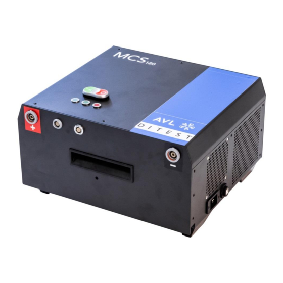
- Page 25 AVL DiTEST MCS 120 Components MCS 120, front view Fig. 2-9 MCS, front view Connector „plus“ (red) Connector “analogue” LEDs Charging / discharging is running Green Device on and ready Blue Device is idle Blue Charging / discharging is running or an error has...
-
Page 26: Cable Sets
Components AVL DiTEST MCS 120 Cable sets 2.1.1 USB-cable (USB 2.0 A auf USB 2.0 B Rugged) EX7069 This cable connects the MCS, socket USB, with the PC, socket USB. Fig. 2-10 USB-Cable USB 2.0 A to USB 2.0 B 2.1.2... -
Page 27: Cable, Can Bus Module
The mains cord set must have a C19 plug for the connection to the MCS 120 suitable for the above current ratings. Connect MCS 120 only to protective contact sockets! Set up the MCS 120 in a way that there is always free access to the power separator! (Power cord from the mains socket). -
Page 28: Spi-Uart-Adapter
Components AVL DiTEST MCS 120 2.1.5 SPI-UART-Adapter The cable is used to connect modules with TPL communication. Fig. 2-14 SPI-UART-Adapter User Manual... -
Page 29: Commissioning
To install the DSS-Software you will need admin rights! To install the DSS Software note the document AT7260 “DSS installation and update”. At the point “Select the application to be installed” select MCS 120 Module Conditioning System”. Firmware Update Note the documentation AT7260, "DSS Installation and Update". -
Page 30: Hardware
Set up the MCS 120 so that adequate ventilation is guaranteed, fans and air vents are not obstructed and the air must circulate freely! Set up the MCS 120 in a way that there is always free access to the power separator! (Power cord from the mains socket). - Page 31 2. Take the basic device (2) from the transport / adapter case (1) and put it as shown right beside the case (3). Fig. 3-2 MCS 120 3. Connect the MCS 120 to the tester via an USB-cable. Make sure that the screw cap on the USB Rugged plug (1) is tight. Fig. 3-3 MCS 120...
- Page 32 Connect MCS 120 only to protective contact sockets! Set up the MCS 120 in a way that there is always free access to the power separator! (Power cord from the mains socket). Version USA: Only oil-resistant cables may be used! Fig.
-
Page 33: Performing A Measurement
AVL DiTEST MCS 120 Performing a Measurement Performing a Measurement Start MCS 120 1. Start the DSS Manager by selecting: Start│Programs│DiTEST│DSS. 2. Select Diagnostic│Module Blancer. Fig. 4-1 Screen DSS Manager User Manual... - Page 34 Performing a Measurement AVL DiTEST MCS 120 3. The start screen appears. Click on Charge/Discharge. Fig. 4-2 Startscreen User Manual...
- Page 35 AVL DiTEST MCS 120 Performing a Measurement 4. This is followed by a screen with safety instructions. WARNING Read and observe the safety instructions on the screen! 5. Pay close attention to the safety instructions and confirm with Next. Fig.4-3...
- Page 36 Performing a Measurement AVL DiTEST MCS 120 6. Choose a cell module type from the drop down list (2) and enter a serial number (3) Input the nominal cell voltage (4). Optional with barcode reading pen: Scan the bar code label attached to the cell module.
- Page 37 AVL DiTEST MCS 120 Performing a Measurement 8. The next screen guides you through the connection process. It is important to do all connecting work in the shown order. WARNING Execute pt. 2 and 3 in the shown order! WARNING...
- Page 38 Performing a Measurement AVL DiTEST MCS 120 Remarks to Connecting a cell module Cable „plus“, „minus“ and cable „CAN“: Fig. 4-6 Connect a cell module To disconnect the "plus" and "minus" cables, pull on the plug: Fig. 4-7 Connecting a cell module Close the cover: Fig.
- Page 39 AVL DiTEST MCS 120 Performing a Measurement 10. The cell module gets charged/discharged now. Section 1 shows all relevant data. By clicking F6 Stop you can stop the charging / discharging process. 11. After the charging / discharging is finished please click Next.
- Page 40 Performing a Measurement AVL DiTEST MCS 120 12. A screen appears which shows you how to disconnect the cell module. Please follow the exact order shown. 13. Continue with Next. Screen „Disconnect cell module“ Fig. 4-10 User Manual...
- Page 41 AVL DiTEST MCS 120 Performing a Measurement 14. On this screen the report is shown. F4 Print Starts a print out of the report. F5 Edit The report can be edited. 15. By pressing F8 Next the charge / discharge process is finished.
-
Page 42: Safety Test
Performing a Measurement AVL DiTEST MCS 120 4.1.1 Safety test 1. Start the DSS Manager by selecting: Start│Programs│DiTEST│DSS. 2. Select Diagnostic│Module Balancer. Fig. 4-12 DSS Manager 3. The start screen appears: Select Safety test. Fig. 4-13 Start screen User Manual... - Page 43 AVL DiTEST MCS 120 Performing a Measurement 4. Connect the cell monitoring cable and close the cover. Continue with Next. Fig. 4-14 Safety test 5. Open the cover and disconnect the monitoring plug. Continue with Next. Fig. 4-15 Safety test...
- Page 44 Performing a Measurement AVL DiTEST MCS 120 6. Is the safety test passed successfully, the following screen appears. With F8 Next to the start screen. Fig. 4-16 Safety test User Manual...
-
Page 45: Self-Test
AVL DiTEST MCS 120 Performing a Measurement 4.1.2 Self-test 1. Start the DSS Manager by selecting: Start│Programs│DiTEST│DSS. 2. Select Diagnostic│Module Balancer. Fig. 4-17 DSS Manager 3. The start screen appears: Select Selftest. Fig. 4-18 Start screen User Manual... - Page 46 Performing a Measurement AVL DiTEST MCS 120 4. Observe the screen, and disconnect the cables shown. Fig. 4-19 Selftest The self-test is performed and the result displayed. Return to the Start screen with Next. Fig. 4-20 Selftest User Manual...
-
Page 47: Deviceinfo
AVL DiTEST MCS 120 Performing a Measurement 4.1.3 Deviceinfo 1. Start the DSS Manager by selecting: Start│Programs│DiTEST│DSS. 2. Select Diagnostic│Module Balancer. Fig. 4-21 DSS Manager 3. The start screen appears: Select Device info. Fig. 4-22 Start screen User Manual... - Page 48 Performing a Measurement AVL DiTEST MCS 120 A screen appears with the device data. With F8 Next to the home screen. Fig. 4-23 Device info User Manual...
-
Page 49: Viewing All Reports
AVL DiTEST MCS 120 Performing a Measurement 4.1.4 Viewing all reports With this function you can manage the result protocols. Click on Result Management. Fig. 4-24 Result management Source Select Local / Network / Saved Results. Period Select Day, Week, Month, Year or All. - Page 50 Performing a Measurement AVL DiTEST MCS 120 Individual logs can be selected by checking a box. F2 Choose Selects all logs. F3 Discard Discards the log selection. F4 Print Prints the selected logs. F5 Delete Deletes the selected logs.
-
Page 51: Result Report Directory
AVL DiTEST MCS 120 Performing a Measurement 4.1.5 Result report directory Result protocols are stored for future use at the default location: “C:\Users\Public\Documents\xxxx“. This location can be changed: Click on ExtrasSettingsAVL DiGate480. Fig. 4-25 Changing the Report protocol directory Result storage for backup by year and month... -
Page 52: Entering A List Of Operator Names
With the button, see fig. 2-10, only the power modules are switched off. The MCS 120 enters Idle, Sleep mode. To disconnect the MCS 120 from the power grid press the red button (Power module off) and disconnect the power cable from the wall outlet. -
Page 53: Troubleshooting
AVL DiTEST MCS 120 Troubleshooting Troubleshooting Maintenance DANGER Danger to life by electrical shock Maintenance is only allowed by AVL DiTEST! Do not open the MCS 120, because exposed parts can have dangerous voltages! User Manual... - Page 54 Troubleshooting AVL DiTEST MCS 120 User Manual...
-
Page 55: Maintenance And Care
AVL DiTEST MCS 120 Maintenance and care Maintenance and care Optical check Carry out a regular optical check of the MCS 120, USB cable and measuring cables with the test adapters. Check for damage and dirt. CAUTION Damaged Parts (power cord, adapter and USB cables) have to be exchanged... - Page 56 Maintenance and care AVL DiTEST MCS 120 User Manual...
-
Page 57: Scope Of Delivery
AVL DiTEST MCS 120 Scope of delivery Scope of delivery Standard delivery: Part ID number Module Conditioning System MCS incl. power cable (GB) Transport box USB cable EX7069 (USB 2.0 A - USB 2.0 B Rugged) Cable Plus-Minus, X590 Plus & Minus cable with knurled nut M6... - Page 58 Scope of delivery AVL DiTEST MCS 120 Spare parts: Part ID number USB cable EX7069 (USB 2.0 A - USB 2.0 B Rugged) Cable Plus-Minus, X590 Plus & Minus cable with knurled nut M6 Cable analogue module, X590 Analogue module cable adapter...
-
Page 59: Technical Data
10 to 80 %, humidity non condensing Disposal: This AVL DiTEST product is a high-quality electrical and electronic device that must not be disposed of in the household waste. When disposing of this system, you must comply with your local legal requirements! - Page 60 Technical data AVL DiTEST MCS 120 User Manual...
-
Page 61: Index
AVL DiTEST MCS 120 Index Index Cable Set plus minus, X590 16 Maintenance 43 Cable sets 16 Maintenance and care 45 Cable, analog module, X590 VII, 16 Cable, CAN bus module 17 Certificate of Calibration 4 Operating data 49 Cleaning 45... - Page 62 Index AVL DiTEST MCS 120 User Manual...
Need help?
Do you have a question about the MCS 120 and is the answer not in the manual?
Questions and answers