
Subscribe to Our Youtube Channel
Summary of Contents for GMI D5202S
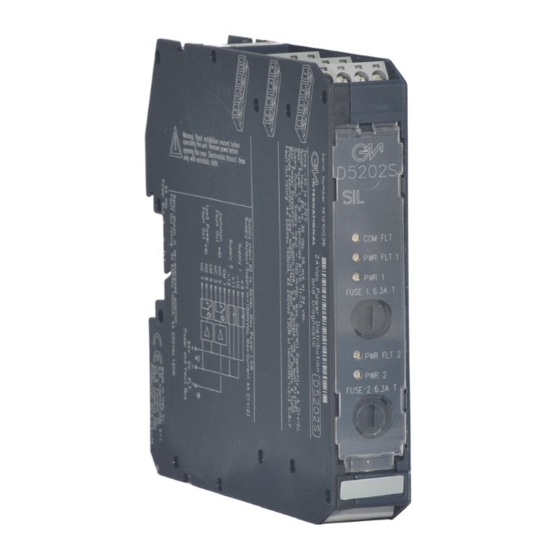
- Page 1 D5202S INSTRUCTION & SAFETY MANUAL 4 A, 24 Vdc, SIL 3 Power Distribution and Diagnostic Module DIN-Rail, Model D5202S D5202S - 4 A, 24 Vdc, SIL 3 Power Distribution and Diagnostic Module G.M. International ISM0177-4...
-
Page 2: Technical Data
5x20, 6 A fuses. 2 SPDT relay contacts provide remote alarming for the above mentioned failures. In case of fault of one supply source the D5202S exchanges to the working one using a circuit (ideal diodes) with just a few mW dissipation, thus increasing reliability and greatly reducing internal power dissipation. -
Page 3: Ordering Information
Power Supply 1: (+) Positive pole Power Supply 1: (-) Negative pole Power Supply 2: (+) Positive pole Power Supply 2: (-) Negative pole G.M. International ISM0177-4 D5202S - 4 A, 24 Vdc, SIL 3 Power Distribution and Diagnostic Module... - Page 4 9-11 and 10-12 Relay contacts shown in de-energized position. Terminals 1-2 and 5-6 are open; terminals 1-3 and 5-7 are closed. D5202S - 4 A, 24 Vdc, SIL 3 Power Distribution and Diagnostic Module G.M. International ISM0177-4...
- Page 5 Power Supply 1 source (20÷30 Vdc) is applied to Pins 9(+) - 10(-) and Power Supply 2 source (20÷30 Vdc) is applied to Pins 11(+) - 12(-). The following table describes the OFF operation (absence of supply on Power Bus) and the ON operation (presence of 20÷30 Vdc supply on Power Bus) of the D5202S,...
- Page 6 Functional Safety Manual and Applications The D5202S can repeat the common fault signal from the Power and Fault Bus, therefore considering all diagnostic functions enabled, the cumulative fault diagnostic functionality is described by the following table, where the status (open or closed) of Common Fault output contact is related to the common fault signal:...
-
Page 7: Operation
Warning D5202S is an electrical apparatus installed into standard EN50022 T35 DIN-Rail located in Safe Area or Zone 2, Group IIC, Temperature Classification T4, Hazardous Area (according to EN/IEC60079-15) within the specified operating temperature limits Tamb - 40 to +60 °C. - Page 8 This configuration is useful when D5202S must not repeat any common fault signal from the Power and Fault Bus. ON ON OFF OFF OFF D5202S - 4 A, 24 Vdc, SIL 3 Power Distribution and Diagnostic Module G.M. International ISM0177-4...
Need help?
Do you have a question about the D5202S and is the answer not in the manual?
Questions and answers