
Summary of Contents for +Collins Youldon SDM09H
- Page 1 Product Manual Hosereels – Hydraulic Rewind Installation and Maintenance Manual (Technical Manual No SDM09H) SDM09H-Hosereel Issue 2 – April’20...
-
Page 2: Table Of Contents
Valve port connection Typical hydraulic system schematic Friction brake Fixed roller guides Hinged roller guides Earth continuity device Swing out platform Typical swingjoint / fluid path assembly (1½” and 2”) Tables 1 Problem solving SDM09H-Hosereel Page 1 Issue 2 – April’20... -
Page 3: Scope Of This Manual
1” 1¼” 1½” 2” Date of purchase Collins Youldon has a policy of continual product improvement, and reserves the right to modify the design, or materials used, at any time in the future. SDM09H-Hosereel Page 2 Issue 2 – April’20... -
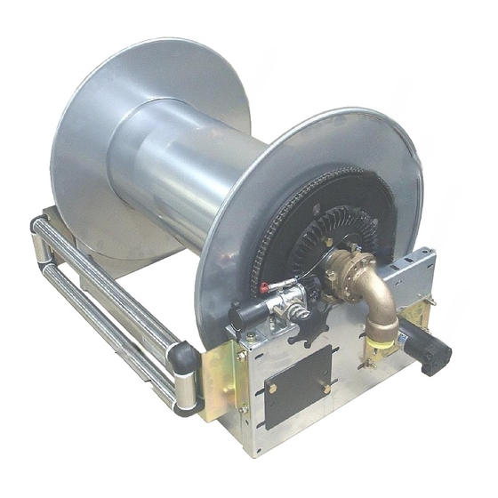
Page 4: Typical Hydraulic Motor Rewind Hosereel
Centre shaft inlet / swingjoint connection Frame Hydraulic motor Hose roller guides (if fitted) Serial number plate Swingjoint Flexible connection Figure 1 – Typical hydraulic motor rewind hosereel (for more part details refer to Appendix 1) SDM09H-Hosereel Page 3 Issue 2 – April’20... - Page 5 Alternatively, they can be galvanised or supplied in stainless steel. 1.2.6 Collins Youldon inspect and test all parts of the hosereel fluid path before despatch. SDM09H-Hosereel Page 4 Issue 2 – April’20...
- Page 6 The centre of gravity is not central to the hosereel; we recommend that a minimum of two persons assist during the movement or installation. The hosereel must only be lifted by the drum (as shown below), or by the frame. Figure 2 – Lifting the hosereel SDM09H-Hosereel Page 5 Issue 2 – April’20...
-
Page 7: Installing The Hosereel
If the hose is too close to the drum at the gooseneck connection point, the drum may be dished locally with a hide mallet. No harm will be done and the hose should then be a snug fit with a smooth profile around the drum. SDM09H-Hosereel Page 6 Issue 2 – April’20... -
Page 8: Installing The Hydraulic Motor
Pressure relief valve – sets the maximum rewind power of the hosereel, and must be set during installation to give a safe maximum rewind torque FOR ALL HOSEREELS SHAFT Ø16mm 7640.OH.M ADAN AMM.32.P (DANFOSS OMM 32) Figure 3 – Hydraulic motor SDM09H-Hosereel Page 7 Issue 2 – April’20... -
Page 9: Typical Hydraulic System Schematic
Lever operated changeover valve – open type spool which will not “dead end” supply. Adjustable flow control valve – excess returned to tank. Combined 3 position control lever and pressure relief valve. Hosereel hydraulic motor. Figure 5 - Typical hydraulic system schematic SDM09H-Hosereel Page 8 Issue 2 – April’20... -
Page 10: Handwheel Friction Brake
These are designed to reduce hose wear. Make sure that the hose will run smoothly off the hosereel drum and between the rollers. 4 - WAY TOP FIXED ROLLER GUIDES 4 - WAY FRONT FIXED ROLLER GUIDES Figure 7 – Fixed roller guides SDM09H-Hosereel Page 9 Issue 2 – April’20... -
Page 11: Hinged Roller Guides
2.5.4 Earth continuity device Where an earth continuity device is fitted to the hosereel the installer must provide a continuity path as appropriate. 4.7mm PLASTIC BEARING. FRAME. Figure 9 – Earth continuity device SDM09H-Hosereel Page 10 Issue 2 – April’20... -
Page 12: Swing Out Platform
Figure 10 – Swing out platform 2.5.6 Remote Rewind If the hosereel is supplied with remote rewind adequate guarding must be fitted to all moving parts and the rewind mechanism must be correctly aligned. SDM09H-Hosereel Page 11 Issue 2 – April’20... -
Page 13: Deploying The Hose
When all the hose has been rewound onto the drum, set the brake to prevent the hosereel from turning. 3.2.6 Finally, ensure that the nozzle and rewind handle are stored safely and the handwind cover is swung closed. SDM09H-Hosereel Page 12 Issue 2 – April’20... -
Page 14: Rewinding The Hose -With The Hydraulic Rewind Motor
After use the platform should be returned to the “parked” position and secured with the spring bolt. Dependant upon the installation there may be additional instructions which should be followed. SDM09H-Hosereel Page 13 Issue 2 – April’20... -
Page 15: Weekly Maintenance
Lubricate the chain with a suitable lubricant. 4.3.5 Examine the hydraulic pipe work for any damage or leaks. Repair any fault found. 4.3.6 Check the control valves for leaks. Repair or replace faulty valves. SDM09H-Hosereel Page 14 Issue 2 – April’20... -
Page 16: Corrective Maintenance
4.5.2.3 Fit the new swingjoint to the hosereel using an appropriate thread sealant. 4.5.2.4 Reconnect the flexible hose to the swingjoint and check for leaks. Replacing Inlet ‘O’ ring or Chevron seal in 1 ½” and 2” swingjoints 4.5.3 SDM09H-Hosereel Page 15 Issue 2 – April’20... - Page 17 Sales department for further assistance. Figure 12 – Typical swingjoint / fluid path assembly (1½“ and 2”) Key to parts Spindle Gooseneck Bearing housing Inlet Shaft Chevron seal (or o ring – see appendix 4 and 5) SDM09H-Hosereel Page 16 Issue 2 – April’20...
- Page 18 At the opposite end of the drum, remove the bolts securing the bearing to the top of the hosereel frame, lift the hosereel drum away from the frame assembly and set aside carefully to avoid damage to the end disks. SDM09H-Hosereel Page 17 Issue 2 – April’20...
- Page 19 Fit the rewind handle (or re-connect the rewind power supply) and check that the rewind operation works correctly, ensuring the gears are correctly meshed and running smoothly and check for any leaks in the fluid path. SDM09H-Hosereel Page 18 Issue 2 – April’20...
-
Page 20: Problem Solving
Replace the motor, section 4.4.2 Product leakage Leaks from swingjoint. Make sure seals are not worn, replace as per section 4.5 Swingjoint defective, replace part or whole assembly as necessary, see section 4.5 SDM09H-Hosereel Page 19 Issue 2 – April’20... - Page 21 Product Manual Appendix 1 Layout drawing – hosereel with hydraulic rewind motor SDM09H-Hosereel Page 20 Issue 2 – April’20...
- Page 22 Product Manual Appendix 2 3/4 “ and 1” Fluid Path Layouts SDM09H-Hosereel Page 21 Issue 2 – April’20...
- Page 23 / FPC.114 Item 5 Nitrile Seal 0216.00.T 0220.00.T 0326.00.T For High Pressure or LPG type swingjoints please contact our sales office for further details. For Working Pressure refer to the Pressure Equipment Directive 97/23/EC SDM09H-Hosereel Page 22 Issue 2 – April’20...
- Page 24 ”] PCD. With 35mm inside dia. Nitrile ‘O’ ring (early models) Seal 7525.22.T 7525.22.T Chevron seal kit 7525.03.V.KIT 7525.03.V.KIT Nitrile ‘O’ ring (all models) Seal 7525.22.T 7525.22.T Viton ‘O’ ring (all models) 7525.22.V 7525.22.V SDM09H-Hosereel Page 23 Issue 2 – April’20...
-
Page 25: 2" Swingjoint / Fluid Path Assemblies
Nitrile ‘O’ ring (early models) Seal 7526.22.T 7526.22.T Viton ‘O’ ring (early models) 7526.22.V 7526.22.V Chevron seal Viton (current models) 7526.17.V.KIT 752617.V.KIT Nitrile ‘O’ ring (all models) Seal 7526.22.T 7526.22.T Viton ‘O’ ring (all models) 7526.22.V 7526.22.V SDM09H-Hosereel Page 24 Issue 2 – April’20...
Need help?
Do you have a question about the SDM09H and is the answer not in the manual?
Questions and answers