
Summary of Contents for FlaktWoods TWIN WHEEL SYSTEM
-
Page 1: Table Of Contents
TWIN WHEEL SYSTEM AIR COMFORT AIR COMFORT AIR TREATMENT 8877 GB 2017.10.25 » ASSEMBLY AND INSTALLATION Contents Page Twin Wheel System Twin Wheel Controls Cabling Guide Using the controller Configuration quick guide 5 - 8 Overview of the menu structure... -
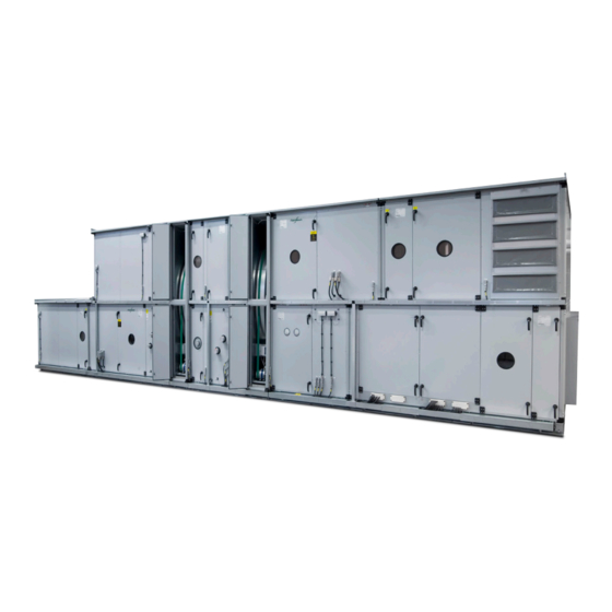
Page 2: Twin Wheel System
Assembly and installation TWIN WHEEL SYSTEM LIMITS OF RESPONSIBILITIES The Twin Wheel system is designed to operate as a part of an air handling unit, delivering a controlled temperature and Although Fläkt Woods has tested and reviewed the documenta- humidity level. In order for the unit to function with intended tion within this manual, Fläkt Woods makes no warranty, neither... -
Page 3: Twin Wheel Controls Cabling Guide
Assembly and installation TWIN WHEEL SYSTEM TWIN WHEEL CONTROLS CABLING GUIDE 1. Locate the cabling for the temperature sensors GT3-TW, 13. Locate the cabling needed from the AHU controller GT4-TW and GT11-TW. See picture on pages 11-12. (described on page 1). See drawing on page 10. -
Page 4: Using The Controller
Assembly and installation TWIN WHEEL SYSTEM USING THE CONTROLLER 2. Info button 5. Knob Press to access the Turn knob clock- Main index wise /anticlockwise to advance or move back • Off = Stop, Re-cooling in the menus. Press • Green, steady glow =... -
Page 5: Configuration Quick Guide
Assembly and installation TWIN WHEEL SYSTEM CONFIGURATION QUICK GUIDE Reset/save commissioning and factory preset settings It is possible to reset the controller back to its original Configuring through the HMI factory settings, Par factory load, and the commissioning If the controller has been supplied in non-configured condition, settings, Par service load, provided that the commissioning it can be configured through a three step process in the HMI. - Page 6 Assembly and installation TWIN WHEEL SYSTEM Alarm acknowledgement Example: Setting the year Alarms are acknowledged by pressing the alarm button (4) The following example shows how the current year is altered in twice. Confirmation/resetting of alarms, Acknowledge, are the controller.
- Page 7 Assembly and installation TWIN WHEEL SYSTEM Terms for summer Sensible rotor Outdoor temp > condensation point for the humidity set point – The sensible rotor regulates so that the supply air temperature Outs tmp diff summer. set point is withheld. Under conditions when the sensible rotor...
- Page 8 Assembly and installation TWIN WHEEL SYSTEM Temperature Deviation relative humidity set point. This is settable in the configuration through the parameter Humidity control. Supervision of temperature error is possible to activate/ deactivate, a lower limit and a maximal difference is Dehumidification (Cooling) configurable.
-
Page 9: Overview Of The Menu Structure
Assembly and installation TWIN WHEEL SYSTEM Menu heading Remark Start page First menu at start up. Shows operational mode and actual values for temperatures ................... Password enter Password is: 1000 ............Main Index The main index ................Unit Status of settings for Twin Wheel .................. -
Page 10: General Notes Controls
Assembly and installation TWIN WHEEL SYSTEM GENERAL NOTES CONTROLS Reaching the supply air set point The supply air set point, delivered by the AHU controller to the Twin Wheel controller may have to be calibrated by measuring any eventual temperature rises past the TW unit, (fan, duct etc). -
Page 11: Connection Twin Wheel And Eq Control Boxes
Assembly and installation TWIN WHEEL SYSTEM CONNECTION TWIN WHEEL AND EQ CONTROL BOXES Pump cooling Ext. heater GT4 Extract air Alarm GT1 Supply air GH1 Supply air Alarm B GT11 Cooling GT3 Outdoor air Set point VVX1 VVX2 VVX1 Alarm... -
Page 12: Twin Wheel Control Box - Wiring Diagram
Assembly and installation TWIN WHEEL SYSTEM TWIN WHEEL CONTROL BOX – WIRING DIAGRAM Fläkt Woods 8877 GB 2017.10.25 Specifications are subject to change without further notice... -
Page 13: Cabling Locations
Assembly and installation TWIN WHEEL SYSTEM CABLING LOCATIONS External External VVX2 VVX1 VVX2 VVX1 Extract Air Extract Air Supply Air VVX1 VVX2 Supply Air VVX1 VVX2 Supply air ground floor, inspection side right 1. RHE1-TW cabling. (Hygroscopic rotor) 2. GT4-TW cabling. - Page 14 Assembly and installation TWIN WHEEL SYSTEM External External VVX2 VVX1 VVX2 VVX1 Supply Air Supply Air Extract Air VVX1 VVX2 Extract Air VVX1 VVX2 Supply air top floor, inspection side right 1. RHE1-TW cabling. (Hygroscopic rotor) 2. GT4-TW cabling. (Extract air sensor) 3.
-
Page 15: Installation And Mounting Gth1-Tw
Assembly and installation TWIN WHEEL SYSTEM INSTALLATION AND MOUNTING GTH1-TW Figure 1 Mounting position GTH1-TW Mounting position GTH1-TW Figure 2 The GTH1 sensor is to be mounted in the supply air. If placed in the AHU unit, it should be on a panel in an empty section. The sensor could also be placed in the supply air duct.