Table of Contents
Advertisement
Quick Links
Model:___________________________________
Serial Number:____________________________
Date of Purchase:__________________________
Windows Product Serial Number: ________________________________________
FM – 6
FERROGRAM MAKER
USER MANUAL
August 2017
Trico Corporation
1235 Hickory Street
Pewaukee, WI 53072
Phone: 262.691.9336
www.tricocorp.com
Revision D
Advertisement
Table of Contents

Summary of Contents for Trico FM-6
- Page 1 FM – 6 FERROGRAM MAKER USER MANUAL Revision D August 2017 Trico Corporation 1235 Hickory Street Pewaukee, WI 53072 Phone: 262.691.9336 www.tricocorp.com Model:___________________________________ Serial Number:____________________________ Date of Purchase:__________________________ Windows Product Serial Number: ________________________________________...
-
Page 2: Table Of Contents
Table of Contents 1. Introduction………………………………………………………………………. 4 1.1 Related Documentation………………………………………………………… 4 2. Packing List and Assembly ……….……………………………………………... 5 2.1 FM-6 Unit Assembly…………………………………………………………... 5 3. Specifications and Operating Parameters………………………………………. 7 3.1 Physical Specifications………………………………………………………... 7 3.2 Power…………………………………………………………………………... 7 3.3 Unit Configuration……………………………………………………………... 7 3.4 Environmental Conditions……………………………………………………... 7 4. - Page 3 11. Troubleshooting and Maintenance………………………………………………. 25 11.1 Troubleshooting……………………………………………………………..25 11.2 Maintenance…………………………………………………………………... 28 11.2.1 Daily Maintenance or as Needed……………………………………… 28 11.2.2 Weekly Maintenance………………………………………………….. 28 11.3 Sample Tube Seal……………………………………………………………. 28 11.4 Over Flow Well……………………………………………………………..29 11.5 Diagnostics……………………………………………………………………. 29 11.5.1 Manual Sensor Checks……………………………………………….. 29 11.5.2 Using the Diagnostic…………………………………………………. 30 11.6 Bubble Level…………………………………………………………………..
-
Page 4: Introduction
Each station includes a holder to correctly position a sample slide over a magnetic field. The FM-6 working in automatic mode, deposits a prepared fluid sample on the slide at a carefully controlled rate. At the end of this sample deposition, a fixing solution washes the sample slide leaving only wear particles and contaminants on the Ferrogram slide for analysis. -
Page 5: Packing List And Assembly
2.1 – FM-6 UNIT ASSEMBLY To assemble the parts, follow these instructions: 1. Carefully remove the FM-6 unit from the box and place it on a hard level work surface or table to support a load greater than 27 lbs (12 kg). - Page 6 9. Rotate the two adjustable feet located under the front of the unit clockwise or counter-clockwise to level the unit. Two bubble levels are located between the magnet assemblies to indicate when the unit is level. 10. Once the unit has been leveled, lower the two support feet that are located under the waste and fixer bays until they make contact with the top of the countertop.
-
Page 7: Specifications And Operating Parameters
Humidity: 50% to 50% non-condensing CAUTION: DO NOT operate the FM-6 with the back panel removed. Unplug the FM-6 from the power supply before removing the back panel for fixer pump adjustments. Check with Trico before removing as this could void the unit warranty. All other repairs must be done at the factory... -
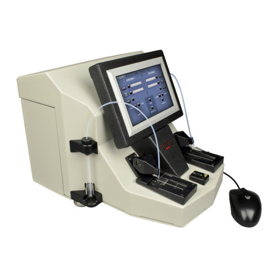
Page 8: Fm Nomenclature
Figure 4.1 4.1 – MAJOR COMPONENTS This section introduces the user to the major components of the FM-6 Ferrogram Maker. The following subparagraphs discuss the major components, their location, and the nomenclature for each item on the FM-6 Ferrogram Maker (refer to Figure 4.1). - Page 9 When in operation, the arm is lowered and the sample tube is inserted into the tube holder at the tip. 12. Model and Serial Number Label: When calling Trico Corporation for repair work on the FM-6, this information will be needed.
-
Page 10: Light Indicators
The sample light turns red when the sample is in the progress of being dispensed and then turns black when empty. Fixer Light: In each station array there is a fixer indicator, when lit yellow the FM-6 is pumping fixer onto the glass substrate. - Page 11 Page 11 of 36...
-
Page 12: Consumables And Accessories
5. Consumables and Accessories It will become necessary to reorder a number of consumables to continue testing on the FM-6 unit. This section contains re-ordering information. Many of the test equipment items should not be reused. Contaminated devices can cause inaccurate or incorrect interpretation. -
Page 13: Fixer Pump Priming Procedure
Ferrograms on each station when the unit sits for prolonged periods of time. After the FM-6 is set-up and ready to run, test the fixer pumps by pressing and holding the bottom button on right and left side of the control panel marked FIXER. If after 60 seconds, the fixer doesn’t flow follow the procedure below. - Page 14 17. Ensure that all components are reset by pressing the “All I/O off” button at the bottom of the Diagnostics screen. 18. Select the RUN FM tab on the touch screen menu and follow the FM-6 procedures outlined in this manual.
-
Page 15: Oil Sample Preparation
For example, 9 ml of filtered oil added to 1 ml of sample produces a 10-to-1 dilution. When filtered oil is used, testing is carried out in the normal manner. Trico offers filtered oil in 400 ml bottles. -
Page 16: Setting Up Dispenser Assembly
7. The dispenser assembly is now ready to use. 7.2.2 – Using the Pipette Dispenser The PN 75-0020 Pipette Dispenser has been calibrated by Trico to dispense one milliliter of liquid when used according to the following directions. 1. Take the pipettor out of the box and become familiar with it. When pressing the plunger at the top of the pipettor it has two stops. -
Page 17: Preparing Oil Sample
7.3 – PREPARING OIL SAMPLE Gravimetric settling of wear particles in lubricating oil starts immediately after a sample is left standing. To obtain a representative sample from a larger sample, the particles must be evenly dispersed. To make a homogenous mixture, the following procedure is recommended: 1. -
Page 18: Run Fm Procedures
To initiate the FM-6, follow these basic procedures: 1. Press the on/off switch on the rear of the FM-6 unit to the on position. The sides of the switch will indicate red, when the FM-6 is on. When the FM-6 is on Windows 7 will go through its start- up operation and then the FM program will automatically boot. -
Page 19: Shut Down Procedures
8.3 – SHUT DOWN PROCEDURES 1. Close FM-6 program. 2. Go to start menu in lower left corner and go to Windows shutdown command. 3. Allow Windows to completely shut down before turning off power to the unit. - Page 20 with exit end resting against the drain head (exit end is defined by the black dot). The glass substrate should lie at the suction head and the upper end should be lying against the substrate support ridge. NOTE: The black circle viewed on the bottom left-hand side indicates the substrate is in the proper position for sample lubricant to flow down the non-wetting barrier.
- Page 21 19. Place Ferrogram into its protective envelope and mark it with the appropriate identification information and/or numbers. 20. Carefully remove the sample tubing and sample vial from the FM-6 and discard. The test is now concluded for automatic cyclic mode.
-
Page 22: Semi-Automatic Cycle
Figure 8.3 – Install Sample Tube in Delivery Arm Figure 8.4 – Index Slide on Magnet Assembly 8.4.2 – Semi-Automatic Cycle The SEMI AUTO button initiates the flow of liquid across the Ferrogram at a controlled rate similar to the auto cycle without the rinse cycle automatically coming on. This is purposely done so you may run odd samples with different wash fluids. -
Page 23: Fixer Cycle
8. Place Ferrogram into its protective envelope and mark it with the appropriate identification information and/or numbers. 9. Carefully remove the sample tubing and sample vial from the FM-6 and discard. The test is now complete for semi-automatic cycle mode. -
Page 24: Configuration
9.1 – POST SAMPLE DELAY CYCLE TIME The delay cycle time factory setting is two minutes. When the FM-6 is dispensing a sample fluid from a vial (either automatic or semi-automatic mode), the delay is how long the sample vial is pressurized after the last of the sample fluid leaves the vial. -
Page 25: Tools And About Tab
User Manual. If the application button is gray and cannot be activated the application is currently not available; but will be in the future. New versions of the FM-6 software can be downloaded off of the Trico website and will update the FM-6 program, offering additional features to the TOOLS tab. -
Page 26: Troubleshooting And Maintenance
Also, refer to the limited warranty page at the end of this manual for additional information. Please return the FM-6 with AC line in its original shipping container if possible. Please do not return the manual, waste bottles, or fixer bottles. - Page 27 Table 11.1 Quick Troubleshooting Procedures Symptom Probable Cause Remedy On/off power switch is in on AC line cord not plugged in or Test cord for correct seating in position. Unit does not operate. damaged. socket or for shorts. AC line fuse blown. Remove fuse and determine if blown.
- Page 28 Disconnection light red Program is running but pumps do Shut down program and restart. not operate in modes. Shut down system and do cold boot. Have unit serviced. Auto or Semi Auto mode does Sample vial not in place or Insert sample vial with sample, not work.
-
Page 29: Maintenance
11.2 – MAINTENANCE The FM-6, like any other laboratory instrument, must be maintained on a regular basis in order to ensure consistent and accurate operation. Daily cleaning of certain areas of the instrument is necessary to ensure repeatability of results and that no important information is advertently lost due to poor operating habits. -
Page 30: Overflow Well
Fluid in the well is then suctioned out for 30 seconds. 11.5 – DIAGNOSTICS The FM-6 runs on the Windows 7 PC platform and is a fully functional minicomputer with limited storage capacity. Trico does not support any Windows operating system. Please contact Microsoft with your Microsoft Windows 7 identification number located on the back cover of the unit for Windows 7 Support. -
Page 31: Using The Diagnostic
2. Place a solid object into the path of the lower sensor, the WASTE FULL system indicator in the middle of the RUN FM tab screen should turn yellow, if not there is a sensor issue. Contact Trico for assistance. - Page 32 2. Press the Sample OFF button and a tick sound should be heard, this is the solenoid opening. 3. If one of the solenoids cannot be heard then solenoid needs to be replaced, contact Trico. 4. If both solenoids cannot be heard but other mechanicals turn on and off such as the waste pump, then both solenoids must be replaced.
-
Page 33: Bubble Level
3. If the waste pump does not function call Trico for servicing. 11.6 – BUBBLE LEVEL The bubble levels located in the middle of the FM-6 are used to level the unit magnets in order to maintain the correct flow across the magnet assembly. Always ensure the magnet level bubbles are leveled by increasing or decreasing the height of the two front adjustable feet by turning them clockwise or counter-clockwise. -
Page 34: Pump Tube Pinching
Substrate Length – Substrates are manufactured to 60 mm in total length. Make sure the substrate sits flat and is not bowed upward or misplacement on the entry end shelf. Magnet Strength – The permanent magnets keep their field strength for an indefinite period. If some question arises on whether magnet strength is suspect, it can be tested with a Gauss or Tesla meter. - Page 35 9. Allow the pump to run for several minute to allow the rollers to work the alcohol around the tubing and relax the pinched area. 10. Turn off Sample 1 and Sample 2 and then press "Motor Off" Check that Pump Tube has been cleared: 1.
-
Page 36: Warranty
Trico will repair (or at its option, replace) at no charge any defective component(s) of Trico’s instruments for twelve (12) months from date of purchase. Trico will repair (or at its option, replace) at no charge any defective component(s) of Trico’s supplies and accessories for ninety (90) days from date of purchase.
Need help?
Do you have a question about the FM-6 and is the answer not in the manual?
Questions and answers