Table of Contents
Advertisement
Quick Links
Advertisement
Table of Contents

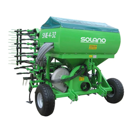
Summary of Contents for SOLANO HORIZONTE SNE Series
- Page 1 PNEUMATIC SEEDER INSTRUCTIONS BOOK SNE MODEL...
- Page 2 CONFORMITY DECLARATION The Company : SOLANO HORIZONTE S.L. Declares, under responsibility, that manchine: Brand: ......SOLANO HORIZONTE Type: ......PNEUMATIC SEEDER Modèle: ......SNE- Nº de série: ....Year of manufacturing: ..Is in conformity with the main requirements of Health and Safety stated in the “REAL DECRETO”...
- Page 3 Dear Customer, SOLANO HORIZONTE has written this book to help you to optimize the use of your seeder. Your seeder has gone through a strict process of safety control in order to ensure a great reliability of its structure and optimize use.
-
Page 4: Table Of Contents
Considerations while you are working......39 Conservation and maintainance........40 Hydraulic engine to run the fan…………………..……… 34 SOLANO HORIZONTE reserves the right to modify at any time and without prior notice the seeder as it judges it necessary, and without any obligation to updated this book. - Page 5 01/ INTRODUCTION You will find in this book all the information about your pneumatic seeder: how to regulate it, how to do maintainance operations, how to deal with potential problems. READ CAREFULLY ALL THE INSTRUCTIONS AND SAFETY RULES BEFORE TO START RUNNING YOUR SEEDER Be sure that : a) all the staff members that work with the seeder have read and understood perfectly the instructions book, and b) that the instructions books is kept in an easy-to-reach place known by all the staff...
-
Page 6: Identification
02/ IDENTIFICATION You will find the identification plate of the seeder on top of the 3 hitching point. (voir Fig. 2-00). Fig. 02.00 If you have any doubts/questions about the seeder, do not hesitate to contact our technical department. - Page 7 03/ EXPLANATIONS ABOUT PICTOGRAMS THAT WARN ABOUT HAZARDS IMPORTANT! Indications about RIGHT and LEFT are to be understood standing from the tractor driver’s seat going forward. 0/ This icon is WARNING about one or more hazards for personnal safety. When you see it in the book or on the seeder, you must pay attention because there is a potential risk of accident.
- Page 8 4/ Be careful and always remain out of reach of the of the working scope of the seeder or of one of its moving elements! The seeder is lifted on top of the ground, thus creating a dangerous area between the seeder and the ground, and a risk of very dangerous accident.
-
Page 9: Safety Norms
04/ SAFETY NORMS In the design of our machines, we have taken into account the main requirements about safety included in the Directive about Machines 89/392/CEE, being very careful with those parts that are likely to cause accidents during working and maintainance operations. We have appropriately protected all the mobile elements that, according to the task they have to perform, can be protected. - Page 10 scope of the seeder and its moving parts. Never forget that the volume of the machine and the potential unexpected and/or abrupt movements of the seeder can catch and injure by surprise anyone that would not respect a safe distance from the seeder and its moving elements.
-
Page 11: When You Receive Your Seeder
05/ WHEN YOU RECEIVE YOUR SEEDER When you receive your seeder, make sure that it corresponds to the model you ordered to your provider, and that no elements nor accessories that you ordered are missing. Make sure that it is in perfect conditions and that you do not see any damage due to transport. -
Page 12: General Indications
GENERAL INDICATIONS Once you have made sure that the delivery is correct and that you have read and understood this book, it is important that you take into account some general considerations: - The pneumatic wheels must have the required pressure. 1000 rpm. -
Page 13: Three Points Hitching
THREE POINT HITCHING The seeder is to be hitched to the 3-point hydraulic elevation system of the tractor, through the union pin (A) of Fig 08.00. To level the seeder, regulate the third point (B) of Fig. 08.-01. Fig.8.00 Fig.8.01... - Page 14 Connecting PTO shaft Before to use PTO shaft, you must read and understand all the instructions mentioned in this book and in the instructions book of the PTO shaft. The PTO shaft work with tubes and spline connections. It works with a rotative movement, being a dangerous element of the seeder.
- Page 15 If the PTO shaft is too long, you will have to cut it (see how to do it in the instruction books of the PTO shaft). This operation must be done by a qulified operator. Before to start the seeder, you have to check that the PTO shaft of the tractor is set at 1000 rpm, and that all the connections (hydraulic and electrical) are correctly done.
- Page 16 08/ RAKE You may have to assemble the rake. If so, you will have 1.- Remove the packaging. 2.- Fix the support bars (A) and (D) to the bracket (B) located on the frame by using the screws (C). You will have to fix tem well, but leaving some mobility to the bar (A).
- Page 17 4.- To orient the tines of the rake regarding the ground, put the screw (G) in one of the six holes (H) drillend in the fixing bracket (F), making sure that the bar (A) always remain under the screw (G). NOTA: You will set the inclination of the rake accoring to how is the ground.
-
Page 18: Hydraulic Markers
09/ HYDRAULIC MARKERS 1.- Lateral hydraulic markers Connect the hydraulic pipes shown in figure 10.01 to the tractor, and set the oil flow with regualtor (B) Fig 1 0 .0 1 Make sure that the moving speed of the arms of the marker is good. - Page 19 the track of the tractor as a reference and you will use the telescopic parts (A) and (B) - fig. 10-02 – whose position is fixed with screws (C) and D). Fig 10.02 To set the furrow made by the marker: A/ You will have to measure the track of the tractor, from the centre of the left pneumatic wheel to the centre of the right pneumatic wheel.
- Page 20 Example: - Working width: 6 metres (600 cm). - Width of the track of the tractor: 1,8 metres (180 cm) - Distance between sowing arms: 12,5 cm. In this example, the marker must be a t 2,225 metres from the last soeing arms: 600-180 = 420:2 = 210+12,5 = 222,5 cm...
-
Page 21: In-Cab Monitor
10/ IN CAB MONITOR B ut to n to c ha n g e t h e d isp la id d a ta s af f ic h ée s à l ’e cr a n Ha co u n ter r e set . P r o gr a m mi n g T h i s b u t t o n i s n o t u s e d The main parameters of the monitor are set in our plant. - Page 22 , whose function is to choose which data will be displayed on the screen. When the seeder is moving, the tramlining data is displayed by default. If you display another data, the screen will automaticaaly display again the tramline data after 10 seconds. 12.1 Working speed The icon in the bottom part of the screen is located on top of...
- Page 23 Once you have displayed the total area, you will move from total 1 ʺtot.1ʺ to total 2 ʺtot.2ʺ (or vice-versa) by pushing the key +1. To reset a total. First choose the total you want to reset pushing the key +1. Keep pressing the key +1 during 5 seconds until the total marks 0.
- Page 24 NOTA: to stop the alarm, solve the problem or switch off and on the monitor. This alarm will not function if your working speed is inferior to 2 km/h. 12.6 Level of hopper The icon the bottom part of the screen is located on top of the icon The monitor does not display the level of the hopper.
- Page 25 11/ DOSIFICATION AND MICRODOSIFICATION. There are two kinsds of seedsIl exite deux type de semences: normal seeds and micro seeds. Figure 15.00 shows you the main elements of the seeding distributor : A g i t a t o r s h a ft Th r e a d e d E n gi n e s h a ft D i s t r i b u t o r...
- Page 26 Micro-seeds. To set the distributor to work with micro-seeds, you will have to: 1) change the position of the locking pieceand 2) change the position of the gears of distribution (which means changing speed). To do so, look carefully at the under figure 15.02. P o s i t i o n fo r n o r m a l s e e d s .
- Page 27 Scheme of the distribution system of seeds...
-
Page 28: Regulation Of The Sowing Dosis
12/ REGULATION OF THE SOWING DOSIS To regulate the sowing dosis, take into account that: 1º.- The type and size of seed that you will use. 2º.- The adaptation of the distrbutor to this kind of seeds. Once you have determined these parameters, you will have to regulate the quantity of seeds that you want to sow. - Page 29 the result obtained in the trial weight in the extent of 5 to 7 %, depending on the ground. So, we have included a 6% compensation factor in the formula that we have used to do the trial weight. To get a more accurate nº of rotation of the crank, mark a line of 50 metres for 4-metre seeders, 40 metres for 5-metre models and 33 metre for 6-metre models.
- Page 30 T A B L E T O D E T E R M I N E S O W I N G D O S I S...
-
Page 31: Emptying The Hopper
13/ EMPTYING THE HOPPER To empty the hopper, see fig. 19-00: open the hatchway (A) by loosening the screw (B). Fig 19-00... -
Page 32: Considerations While You Are Working
14/ CONSIDERATIONS WHILE YOU ARE WORKING When you are sowing, you must pay constant attention to the hopper, so that it never get totally empty. If you let elements like dust, dirtiness, papers, rope accumulate inside the agitator, the sowing dosis will be drastically reduced. Check constantly that the pipe driving the seeds from the hopper to the coulters are not obstructed. -
Page 33: Conservation And Maintainance
15/ CONSERVATION AND MAINTAINANCE: When the sowing season is over, you will to clean the seeder with water using a pressure power washer, cleaining with special care the distributor. Check if you see some deteriorated parts. If so, change them or fix them. Doing so, you will store the seeder ready to be used for the next season. - Page 34 16/ HYDRAULIC ENGINE TO RUN THE FAN (OPTION) This kit is mounted to run the seeder with a hydraulic engine instead of using the PTO shaft. It will be run the oil system of the tractor. Characteristics of the hydraulic engine are: H y dra ul ic eng i ne O il a li me nt a t io n O ver f lo w...
- Page 35 Ctra. Fuente Álamo, 1 * 30153 CORVERA (Murcia) – Espagne Tel: (+34) 968 38 01 13 Fax: (+34) 968 38 04 68 E-mail: export@solano-horizonte.com www s h ri te c...
Need help?
Do you have a question about the SNE Series and is the answer not in the manual?
Questions and answers