Table of Contents
Advertisement
Quick Links
Table of contents
1. General Information ............................................................... 6
1. 1. Symbols used for the instrument ......................................... 6
1. 2. Tilt handle .............................................................................. 6
1. 3. Safety hints ........................................................................... 6
1. 4. Operating Conditions ............................................................ 7
1. 5. Warranty ............................................................................... 8
1. 6. Maintenance ......................................................................... 8
Front panel / Control elements HM6042 .................................. 9
2. Set-up of the instrument ...................................................... 10
2. 1. Safety advice ....................................................................... 10
2. 2. General ................................................................................. 10
2. 3. Selecting the line voltage ..................................................... 10
2. 4. Screen settings .................................................................... 11
2. 4. 1. Adjusting the trace rotation ............................................. 11
2. 4. 2. Adjusting Y-POS./X-POS. ................................................. 11
3. Performing device tests ........................................................ 11
3. 1. Choosing the DUT type ........................................................ 12
3. 2. Setting the test ranges ........................................................ 12
3. 3. Displaying curves ................................................................. 13
3. 4. Measuring device parameters ............................................. 14
3. 5. Using the cursor functions ................................................... 14
3. 6. Memory function, component matching ............................. 15
4. Application examples ............................................................ 15
4. 1. Characteristic curves of a bipolar transistor ......................... 15
4. 2. Characteristic curves of a field effect transistor .................. 16
4. 3. Component matching .......................................................... 16
2
Subject to change without notice
Advertisement
Table of Contents

Related Manuals for Hameg HM6042


Summary of Contents for Hameg HM6042
-
Page 1: Table Of Contents
1. 4. Operating Conditions ............7 1. 5. Warranty ................8 1. 6. Maintenance ................. 8 Front panel / Control elements HM6042 ........9 2. Set-up of the instrument ............10 2. 1. Safety advice ............... 10 2. 2. General ................. 10 2. - Page 2 5, av de la République F - 94800 Villejuif Die HAMEG GmbH / HAMEG S.a.r.l bescheinigt die Konformität für das Produkt The HAMEG GmbH / HAMEG S.a.r.l herewith declares conformity of the product HAMEG GmbH / HAMEG S.a.r.l déclare la conformite du produit...
- Page 3 General information regarding the CE marking HAMEG instruments fulfill the regulations of the EMC directive. The conformity test made by HAMEG is based on the actual generic- and product standards. In cases where different limit values are applicable, HAMEG applies the severer standard.
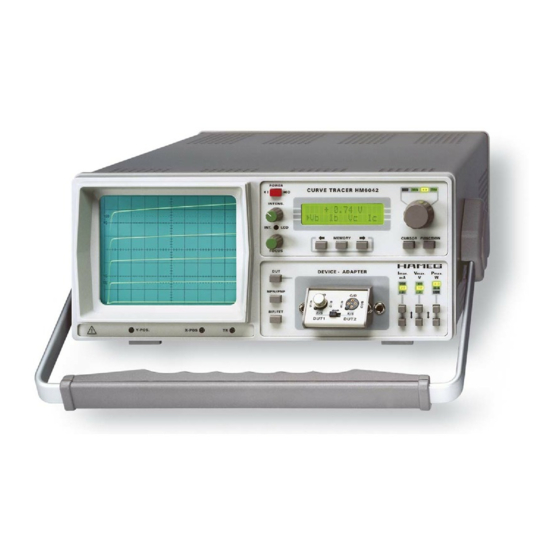
- Page 4 The HM6042 displays a set of 5 curves at a time. All numeric values and parametric data can be read out on a 2x16 digit LCD. Device type and all relevant parameters are selected and modified by a simple front-panel keypad entry.
-
Page 5: General Information
1. General Information The Curve Tracer HM6042 is easy to operate. The logical arrangement of the controls allows anyone to quickly become familiar with the operation of the instrument. However, experienced users are also advised to read through these instructions so that all functions are understood. Immediately after unpacking, the instrument should be checked for mechanical damage and loose parts in the interior. -
Page 6: Operating Conditions
61010-1 correspond to this standard. It has left the factory in a safe condition. This operating manual contains important information and warnings that have to be followed by the user to ensure safe operation and to retain the Curve Tracer in a safe condition. The case, chassis and all measuring terminals are connected to the protective earth contact of the appliance inlet. -
Page 7: Warranty
1. 5. Warranty HAMEG warrants to its customers that the products it manufactures and sells will be free from defects in materials and workmanship for a period of two years. This warranty shall not apply to any defect, failure or damage caused by improper use or inadequate maintenance and care. -
Page 8: Front Panel / Control Elements Hm6042
Front panel / Control elements HM6042 (1) POWER (13)TR Power switch (mains). Adjust the trace rotation. (2) INTENS (14)DUT (push button) Adjust the beam intensity. Start/stop test, connect/disconnect the Device Under Test (3) FOCUS (15)BIP/FET (switch) Adjust the beam sharpness. -
Page 9: Set-Up Of The Instrument
Due to its measuring technique voltages up to 50 V are present at the 4 mm banana jacks, marked as E/S, C/D, and B/G. Therefore, it is assumed that the HM6042 will only be operated by qualified personnel which is acquainted with the danger involved. -
Page 10: Screen Settings
CRT screen at the front panel of the instrument. 3. Performing device tests As soon as the HM6042 is switched on, a baseline is visible at the CTR screen as long as no DUT (Device Under Test) is inserted. A bright spot on the line indicates the current cursor position. -
Page 11: Choosing The Dut Type
The inactive state is indicated on the LCD by the message -off-. 3. 1. Choosing the DUT type The HM6042 has to be set-up according to the type of DUT (Device Under Test) to be proved. To test NPN bipolar transistors switch BIP/FET (15) and switch NPN/PNP (16) has to be in released position. -
Page 12: Displaying Curves
Five curves (I = f(U ), ID = f(U )) normally are displayed on the screen to represent the characteristic behavior of a transistor under test. After selecting the MIN or MAX setting with the push button called FUNCTION (9) the rotary knob can be used to modify the minimum/maximum base current/gate voltage in a sense that the five curves fit for the operating range to be evaluated. -
Page 13: Measuring Device Parameters
The cursor (highlighted dot) indicates the point on a characteristic curve where the actual value is going to be digitized by the instrument. After the HM6042 has been powered on, the cursor will appear on the third of the five characteristic curves. -
Page 14: Memory Function, Component Matching
The three curves between these two are going to be displayed in equal distances. After the HM6042 is powered on, the base current is set to its minimum value. Subject to change without notice... -
Page 15: Characteristic Curves Of A Field Effect Transistor
7. Use the cursor functions (FUNCTION (9), CURSOR (8)) and choose the parameter to be calculated by the instrument and displayed on the LCD (← →, ← →, ← →, 5) by pressing the appropriate keys. ← →, ← →, 4.
Need help?
Do you have a question about the HM6042 and is the answer not in the manual?
Questions and answers