Advertisement
Assembling the GH11
When you first unbox the GH11 you will find its parts in a disassembled state in the included bag
making it as compact as possible for storage and travel. Begin by removing all 4 components
which include the: main body of the GH11, Platform (6), Smooth-control Handle (9), and Quick
Release Plate (15).
Set the QR Plate (15) aside for now. Connecting the plate is explained in the next section of this
manual.
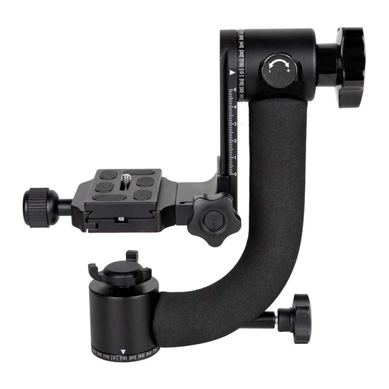
Take ahold of the Platform (6) and loosen its Platform Knob (5). Now slide the Platform (6) onto
the Arm (3) so it appears like the main figure in the Parts Diagram. The Platform (6) will reach a
stopping point at the bottom of the Arm (3). Now tighten the Platform Knob (5) to hold it in place.
Locate the Smooth-control Handle (9). The use of this handle is optional. The Smooth-control
Handle (9) offers greater leverage and control over your camera rig and can be especially useful
when taking video footage. To attach the Smooth-control Handle (9) loosen the Arm Tension
Control Knob (1) as well as the Arm Lock Knob (2). Rotate the Arm (3) and Platform (6) about 90
degrees upward so the bottom of the Platform (6) is facing you while the Arm (3) is to your left.
Notice the connection port in the bottom of the Platform (6) directly on the underside of the Quick
Release Receiver (7). Attach the Smooth-control Handle (9) to this area and use the Smooth-
control Handle Attachment Knob (10) to tighten it in place. Notice the Smooth-control Handle (9)
can be attached in a variety of phase positions. Begin with a position similar to that shown in the
main figure. As you become proficient you may choose to place it in a different position, depending
on your rig and the desired movement. Once the handle is attached, return the Arm (3) and
Platform (6) to its normal resting position.
Now mount the GH11 to your tripod, or other mounting base, as you would a typical photographic
head. Be sure it is attached firmly and all grub screws (where applicable) on your tripod are
properly tightened.
Attaching Your Camera, Lens, or Rig to the GH11
Attach the Quick Release Plate (15) to the tripod port on the bottom of your camera, video camera,
or lens. The Quick Release Plate (15) includes a standard ¼"-20 attachment bolt. If your camera or
Advertisement
Table of Contents

Subscribe to Our Youtube Channel
Related Manuals for pro master GH11


Summary of Contents for pro master GH11
- Page 1 Assembling the GH11 When you first unbox the GH11 you will find its parts in a disassembled state in the included bag making it as compact as possible for storage and travel. Begin by removing all 4 components which include the: main body of the GH11, Platform (6), Smooth-control Handle (9), and Quick Release Plate (15). Set the QR Plate (15) aside for now. Connecting the plate is explained in the next section of this manual. Take ahold of the Platform (6) and loosen its Platform Knob (5). Now slide the Platform (6) onto the Arm (3) so it appears like the main figure in the Parts Diagram. The Platform (6) will reach a stopping point at the bottom of the Arm (3). Now tighten the Platform Knob (5) to hold it in place. Locate the Smooth-control Handle (9). The use of this handle is optional. The Smooth-control Handle (9) offers greater leverage and control over your camera rig and can be especially useful when taking video footage. To attach the Smooth-control Handle (9) loosen the Arm Tension Control Knob (1) as well as the Arm Lock Knob (2). Rotate the Arm (3) and Platform (6) about 90 degrees upward so the bottom of the Platform (6) is facing you while the Arm (3) is to your left. Notice the connection port in the bottom of the Platform (6) directly on the underside of the Quick Release Receiver (7). Attach the Smooth-control Handle (9) to this area and use the Smooth- control Handle Attachment Knob (10) to tighten it in place. Notice the Smooth-control Handle (9) can be attached in a variety of phase positions. Begin with a position similar to that shown in the main figure. As you become proficient you may choose to place it in a different position, depending on your rig and the desired movement. Once the handle is attached, return the Arm (3) and Platform (6) to its normal resting position. Now mount the GH11 to your tripod, or other mounting base, as you would a typical photographic head. Be sure it is attached firmly and all grub screws (where applicable) on your tripod are properly tightened. Attaching Your Camera, Lens, or Rig to the GH11 Attach the Quick Release Plate (15) to the tripod port on the bottom of your camera, video camera, or lens. The Quick Release Plate (15) includes a standard ¼”-20 attachment bolt. If your camera or...
- Page 2 Before mounting your rig to the GH11, tighten the Arm Lock Knob (2) and the Base Lock Knob (13). With the QR Plate (15) firmly attached to your equipment, open the jaws of the Quick Release Receiver (7) by turning the Quick Release Knob (8) counterclockwise. Place the QR Plate (15) into the receiver. Continue to hold your rig as you now firmly tighten the Quick Release Knob (8). Once you are sure the QR Plate (15) is firmly connected to the GH11 you can slowly let go of it. Take note of the two safety bolts in the bottom of the QR Plate which prevent the plate from accidentally sliding out of the gimbal. These bolts can be removed but be cautious in doing this as your equipment can slide out of the gimbal and fall more easily. Operating the GH11 Begin by balancing your rig. With the Base Lock Knob (13) tightened, slowly/slightly loosen the Arm Lock Knob (2) followed by the Arm Tension Control Knob (1). If the Arm (3) of the GH11 begins to move, the rig is out of balance. Tighten the Arm Tension Control Knob (1). With a firm hold on your rig slightly loosen the Quick Release Knob (8). Once this knob is loosened enough to slide the rig and its QR Plate (15) within the Quick Release Receiver (7), slide it forward or backward a little bit to counteract the movement of the Arm (3). Tighten the Quick Release Knob (8) and repeat these steps again until a balance point is achieved. Now you will adjust the gimbal so your rig pivots properly, rather than swings. Loosen the Platform Knob (5) and slide your rig upward with the Platform (6) along the Arm (3) until the center of your lens is aligned vertically with the white triangle-shaped marker at the top of the Vertical Adjustment Scale (4). The “center of your lens” refers to the vertical center of its barrel. You can also use the vertical center of the lens-to-camera mount as a visual guide for this. Once you have found this proper pivot-point for the lens, tighten the Platform Knob (6) and once again loosen the Arm Tension Control Knob (1) slowly. Your camera should remain in place, level on the GH11. If it does not, repeat the balancing process as described in the above paragraph. With your camera and lens attached and balanced you can now enjoy using the GH11. For fast action type movements loosen the Base Lock Knob (13), the Pan Tension Control Knob (11), the Arm Tension Control Knob (1), and the Arm Lock Knob (2). A properly balanced rig will provide fast movements for quick tracking of objects with these controls loosened. This is how most traditional gimbals are used. The GH11 is also capable of smooth, controlled movements. Apply some tension using the Arm Tension Control Knob (1) and the Pan Tension Control Knob (11) to slow down and control the movements in a fluid-like fashion. Use different amounts of tension on these controls to achieve your desired movement or lock one in place to isolate movement to just the other. Use the Smooth-control Handle (9) to apply movement to the GH11 in the most controlled fashion. This is especially useful when capturing video footage and when using smaller, lighter-weight cameras, lenses, or camcorders which lack the mass to create much leverage. • Note, the Arm Lock Knob (2) must always be loosened before the Arm Tension Control Knob (1) will function. The Base Lock Knob (13) must always be loosened before the Pan Tension...
- Page 3 Operational Tips 1. The GH11 is rated with a maximum load capacity of 13 lbs 4 oz / 6 kg. This assumes a properly balanced load. If the camera and lens are not properly balanced there is a danger of tipping and falling which could lead to damage to your equipment or to your person. Always be sure to properly balance your rig. 2. Be advised that while the GH11 can handle a load up to 13 lbs 4 oz / 6 kg, your tripod (with the GH11 attached) must also be able to handle this load, including movements you will apply to the rig via the gimbal (swings and pans). Here are some tips to help ensure a stable tripod setup: If possible, attach the GH11 directly to the column platform of your tripod. Do not connect the GH11 to a ball head or pan/tilt head as this will reduce stability. Always use the tripod’s legs to achieve your desired working height rather than its column. Only extend the column if absolutely necessary. Extending the column of the tripod greatly reduces stability. If your tripod has multi-angle legs and you can achieve your desired working height with the legs set at a wider angle, thereby creating a larger base, do so. This improves stability. Always be sure your tripod is level even if the ground it is placed on it not. Use the leg adjustments to achieve a level state for the gimbal before mounting your camera and balancing it. 3. Cold weather performance is only a guide. The GH11’s performance in cold weather can be affected by moisture as well as temperature and load. With increases in moisture and/or decreases in temperature you will notice the GH11’s movements begin to slow down as the unit’s joints become stiff. In this case you may want to be sure all of the tension adjustments on the GH11 are set to their loosest setting to regain movement. If possible, do your best to keep the GH30C dry to prevent moisture from affecting performance. ONE YEAR UNCONDITIONAL WARRANTY If for any reason, this ProMaster product fails within ONE YEAR of the date of purchase, return this product to your ProMaster dealer and it will be exchanged for you at no charge. ProMaster products are guaranteed for ONE FULL YEAR against defects in workmanship and materials. If at any time after one year, your ProMaster product fails under normal use, we invite you to return it to ProMaster for evaluation. Code 4756 Made in China WWW.PROMASTER.COM | FAIRFIELD, CT 06825...
- Page 4 Arm Tension Control Knob (1) Arm Lock Knob (2) Reverse View Arm (3) Vertical Adjustment Scale (4) Platform Knob (5) Platform (6) Quick Release Quick Release Plate (15) Knob (8) Smooth-control Quick Release Handle (9) Receiver (7) Smooth-control Handle Attachment Knob (10) Pan Tension Control Knob (11)
Need help?
Do you have a question about the GH11 and is the answer not in the manual?
Questions and answers